


Idiomas
Páginas
Jurídico


Earthing
IEEE 80 2000IEEE 80 2000
A Review
safety thru design 1

Essentials of Earthing DesignEssentials of Earthing Design
Crossection Area Current Density Dangerous Potentials
Resistance
The Crossection of Continuous Step potential Horizontal PlaneF
The Crossection of the conductor to be sufficient for carrying GRID
Continuous surface current density
Step potential Horizontal Plane
Touch potential Vertical Plane
OR
carrying GRIDfault current
InstantaneousSurface current
Mesh Potential Mutual resistanceGO
Surface current density
GPRTT
Transfer PotentialEN
safety thru design 2
PASS PASS PASSPASS OK
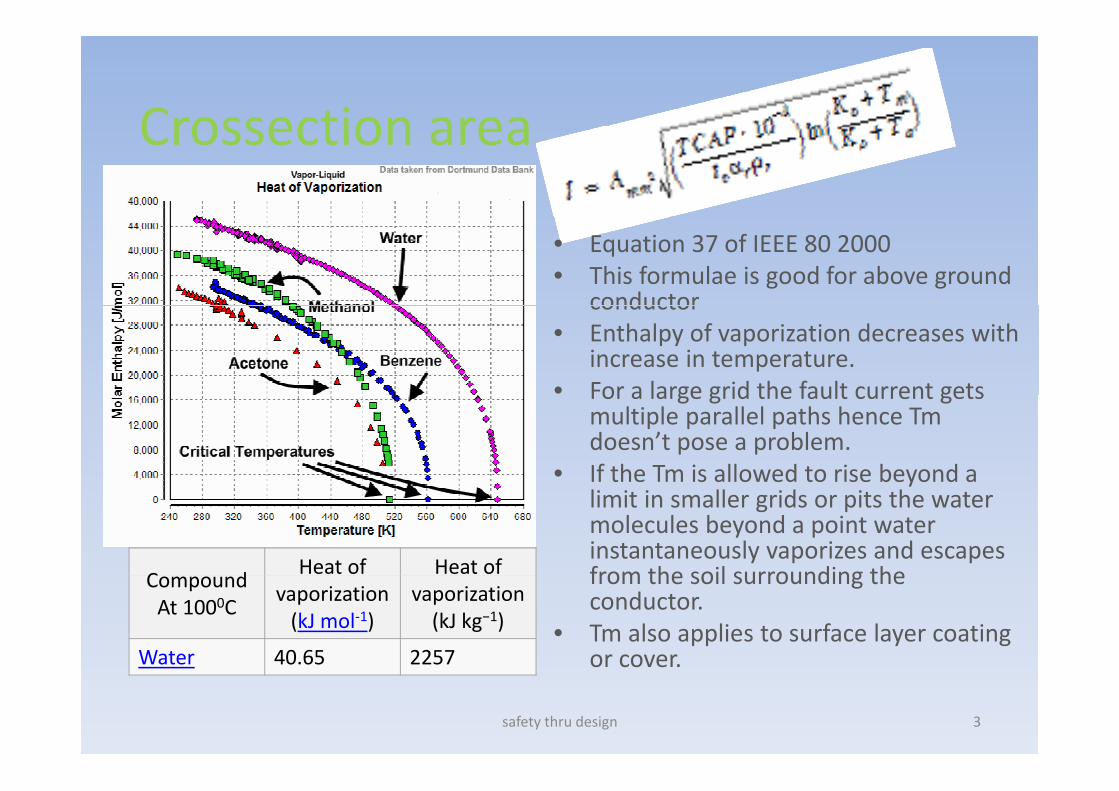
Crossection areaCrossection area
• Equation 37 of IEEE 80 2000• This formulae is good for above ground
conductorconductor• Enthalpy of vaporization decreases with
increase in temperature.• For a large grid the fault current getsFor a large grid the fault current gets
multiple parallel paths hence Tm doesn’t pose a problem.
• If the Tm is allowed to rise beyond a ylimit in smaller grids or pits the water molecules beyond a point water instantaneously vaporizes and escapes from the soil surrounding theC d
Heat of Heat of from the soil surrounding the conductor.
• Tm also applies to surface layer coating or cover.
CompoundAt 1000C
vaporization(kJ mol‐1)
vaporization(kJ kg−1)
Water 40.65 2257 or cover.
safety thru design 3

Evaluation of CrossectionEvaluation of Crossection
M h i l El t i lMechanical ElectricalTm 1510 99T 20 20Ta 20 20
TCAP 3.28 3.28tc 1 0.3c
αr 0.0016 0.0016ρr 15.9 15.9I 25 25
K0 605 605A 199 41 349 54A 199.41 349.54
safety thru design 4

Surface current density as per BS7340 clause 15
If surface current densities are not maintained, junction between electrode and soil, will heat up above
1000C failing the electrode or grid
Long term surface Currents Short Term surface currents
1000C failing the electrode or grid.
g
• Long term Surface current densit is 40A/m2
• Given by the formula 1000*Sqrt(57 7/(ρ*t))density is 40A/m2
• Independent of soil resistivity
1000*Sqrt(57.7/(ρ*t))
• Dependent on soil resistivity and time of clearance ofresistivity and time of clearance of fault
safety thru design 5
Long term Surface Current DensityLong term Surface Current Density
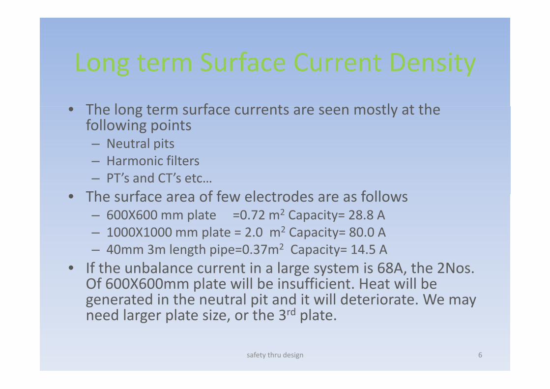
Th l t f t tl t th• The long term surface currents are seen mostly at the following points– Neutral pitsp– Harmonic filters– PT’s and CT’s etc…
• The surface area of few electrodes are as follows• The surface area of few electrodes are as follows– 600X600 mm plate =0.72 m2 Capacity= 28.8 A– 1000X1000 mm plate = 2.0 m2 Capacity= 80.0 Ap p y– 40mm 3m length pipe=0.37m2 Capacity= 14.5 A
• If the unbalance current in a large system is 68A, the 2Nos. Of 600X600mm plate will be insufficient Heat will beOf 600X600mm plate will be insufficient. Heat will be generated in the neutral pit and it will deteriorate. We may need larger plate size, or the 3rd plate.
safety thru design 6
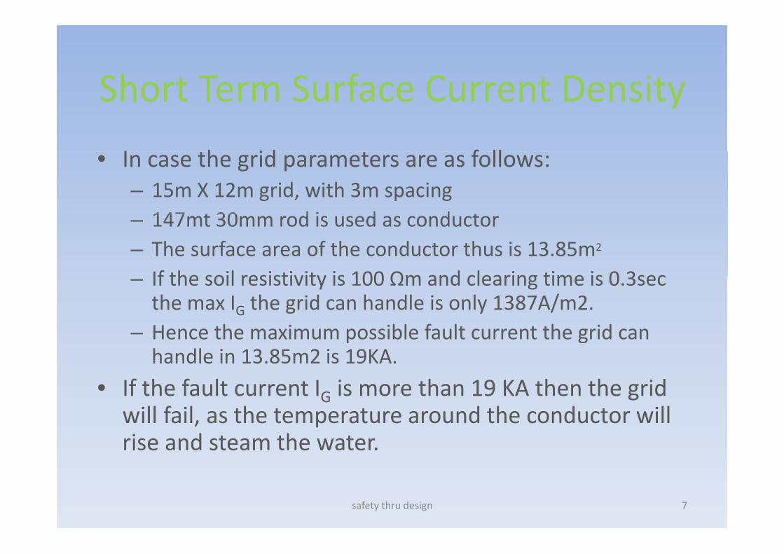
Short Term Surface Current DensityShort Term Surface Current Density
I h id f ll• In case the grid parameters are as follows:– 15m X 12m grid, with 3m spacing147 t 30 d i d d t– 147mt 30mm rod is used as conductor
– The surface area of the conductor thus is 13.85m2
If the soil resistivity is 100 Ωm and clearing time is 0 3sec– If the soil resistivity is 100 Ωm and clearing time is 0.3sec the max IG the grid can handle is only 1387A/m2.
– Hence the maximum possible fault current the grid can p ghandle in 13.85m2 is 19KA.
• If the fault current IG is more than 19 KA then the grid will fail, as the temperature around the conductor will rise and steam the water.
safety thru design 7

Symbol unit ValueFault Current IG KA 23000 Input
Diameter of electrode d m 0.04 Input
Length of Electrode
Soil ls m 37 Input
l 1 IWater lw m 1 Input
Resistivity
Soil ρs Ωm 360 Input
Water ρ Ωm 2 InputWater ρw Ωm 2 Input
Resistance
Soil Rs Ω 12.25394 Equation 55 IEEE 80 2000
Water R Ω 1 368891 Equation 55 IEEE 80 2000Water Rw Ω 1.368891 Equation 55 IEEE 80 2000
Combined Rc Ω 1.231338
Permissible Current Density
Soil σ A/m2 730.9304 Clause 15.2 BS7340σs A/m 730.9304 Clause 15.2 BS7340
Water σw A/m2 9806.46 Clause 15.2 BS7341
Area
Soil As m2 4.6472 πdlss s
Water Aw m2 0.1256 πdlw
Current Division Resistance Capacity Design
Soil 2311.1568 3396.779785 1
Water 20688.843 1231.691433 17
safety thru design 8
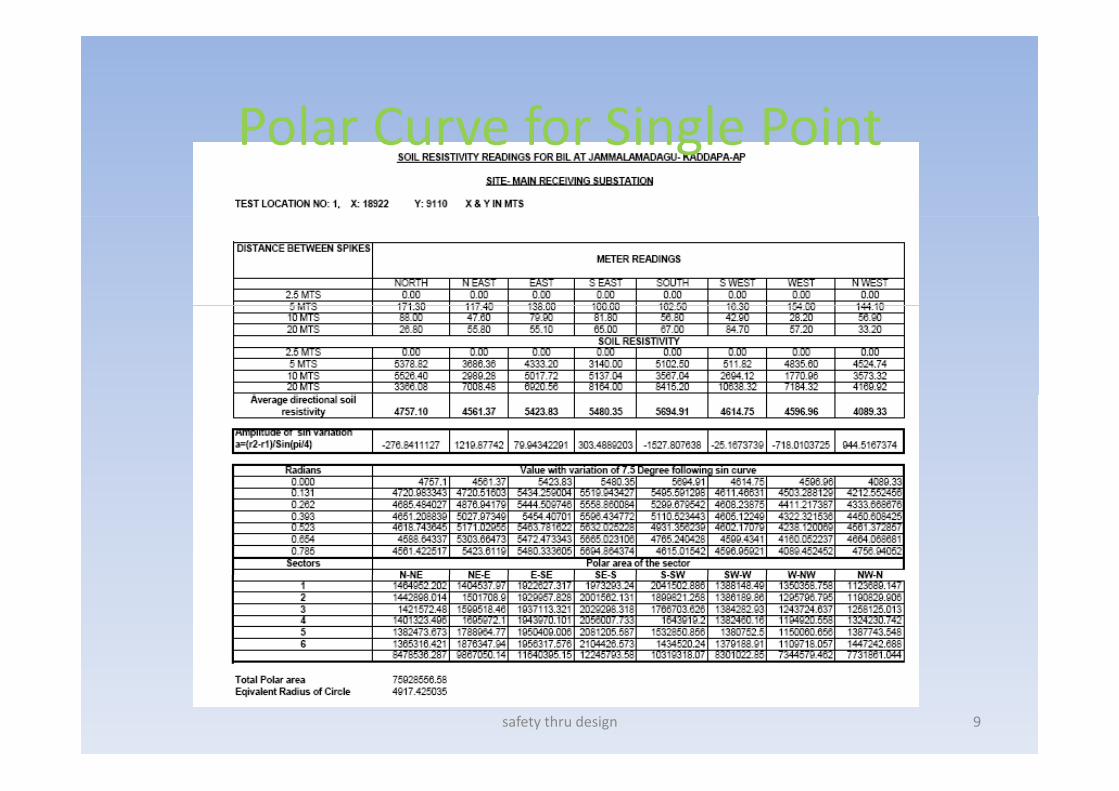
Polar Curve for Single PointPolar Curve for Single Point
safety thru design 9
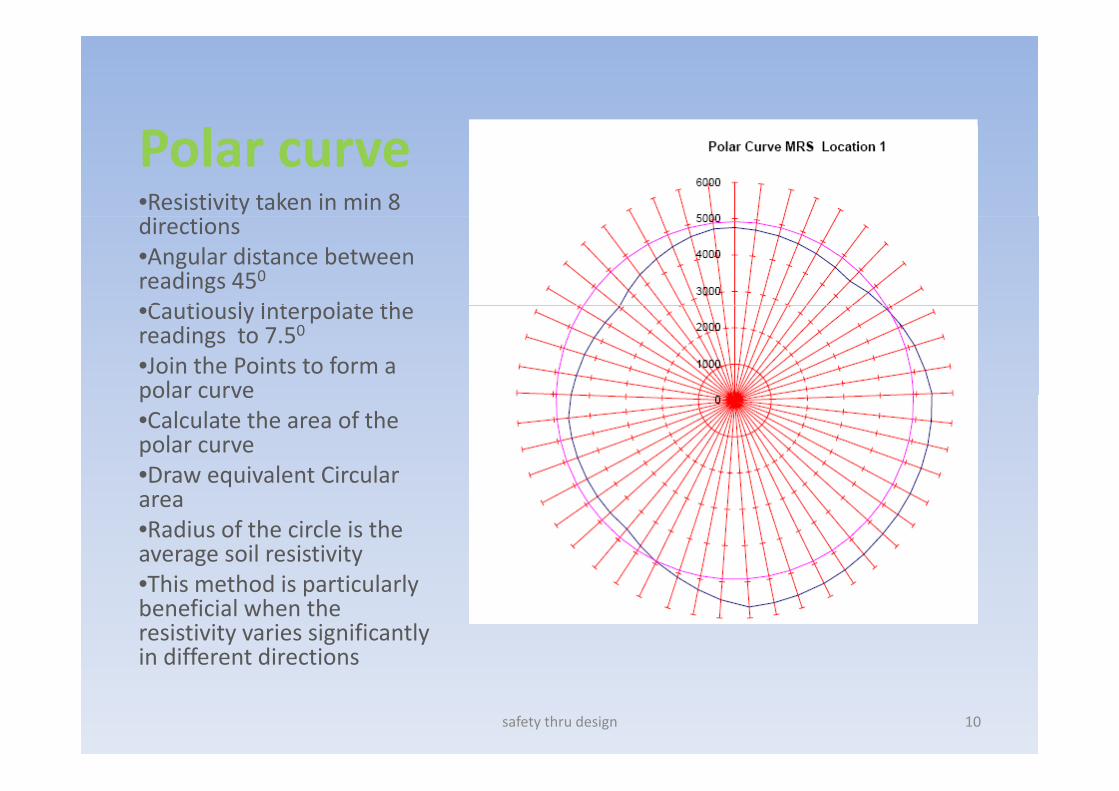
Polar curve•Resistivity taken in min 8 directions•Angular distance between readings 450
C ti l I t l t th•Cautiously Interpolate the readings to 7.50
•Join the Points to form a polar curvepolar curve•Calculate the area of the polar curve•Draw equivalent Circular qarea•Radius of the circle is the average soil resistivityh h d l l•This method is particularly
beneficial when the resistivity varies significantly in different directions
safety thru design 10

Variation in Resistivity in horizontal plane
safety thru design 11
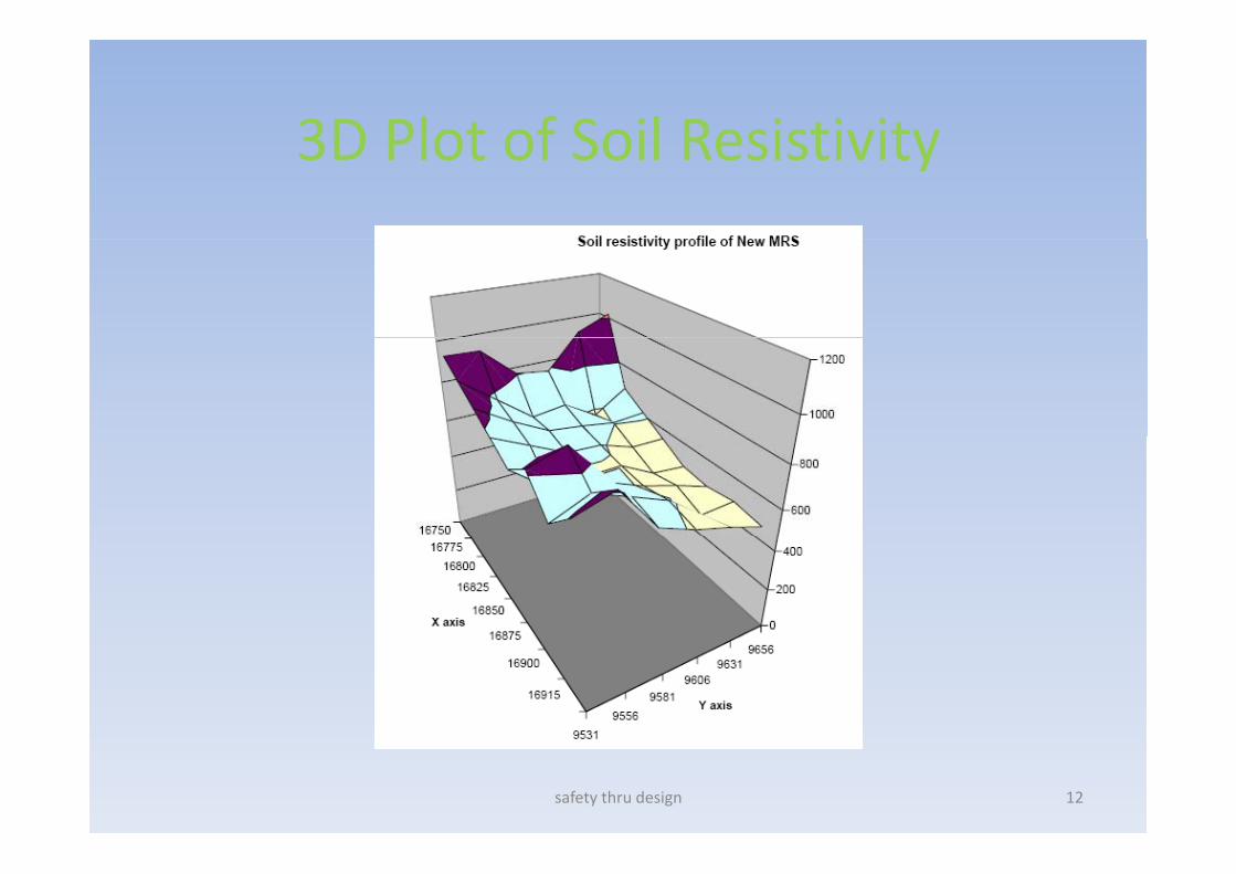
3D Plot of Soil Resistivity3D Plot of Soil Resistivity
safety thru design 12
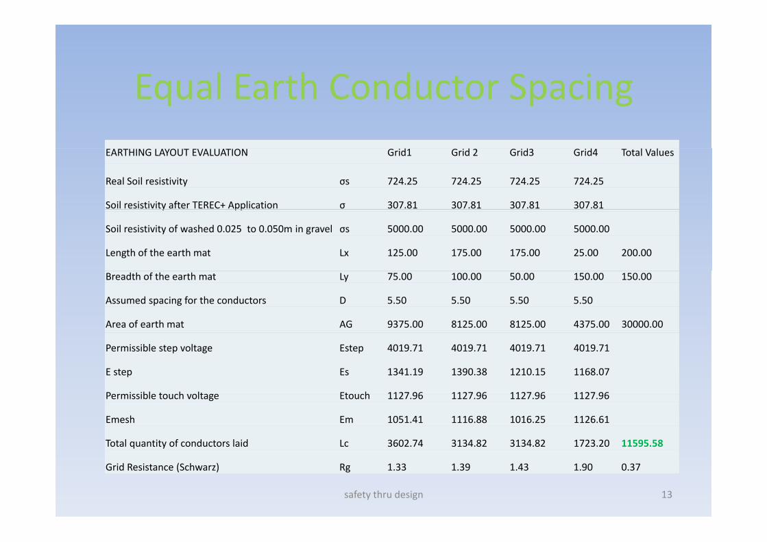
Equal Earth Conductor SpacingEqual Earth Conductor Spacing EARTHING LAYOUT EVALUATION Grid1 Grid 2 Grid3 Grid4 Total Values
Real Soil resistivity σs 724.25 724.25 724.25 724.25
Soil resistivity after TEREC+ Application σ 307.81 307.81 307.81 307.81y pp
Soil resistivity of washed 0.025 to 0.050m in gravel σs 5000.00 5000.00 5000.00 5000.00
Length of the earth mat Lx 125.00 175.00 175.00 25.00 200.00
Breadth of the earth mat Ly 75.00 100.00 50.00 150.00 150.00
Assumed spacing for the conductors D 5.50 5.50 5.50 5.50
Area of earth mat AG 9375.00 8125.00 8125.00 4375.00 30000.00
Permissible step voltage Estep 4019.71 4019.71 4019.71 4019.71
E step Es 1341.19 1390.38 1210.15 1168.07
Permissible touch voltage Etouch 1127 96 1127 96 1127 96 1127 96Permissible touch voltage Etouch 1127.96 1127.96 1127.96 1127.96
Emesh Em 1051.41 1116.88 1016.25 1126.61
Total quantity of conductors laid Lc 3602.74 3134.82 3134.82 1723.20 11595.58
Grid Resistance (Schwarz) Rg 1.33 1.39 1.43 1.90 0.37
safety thru design 13
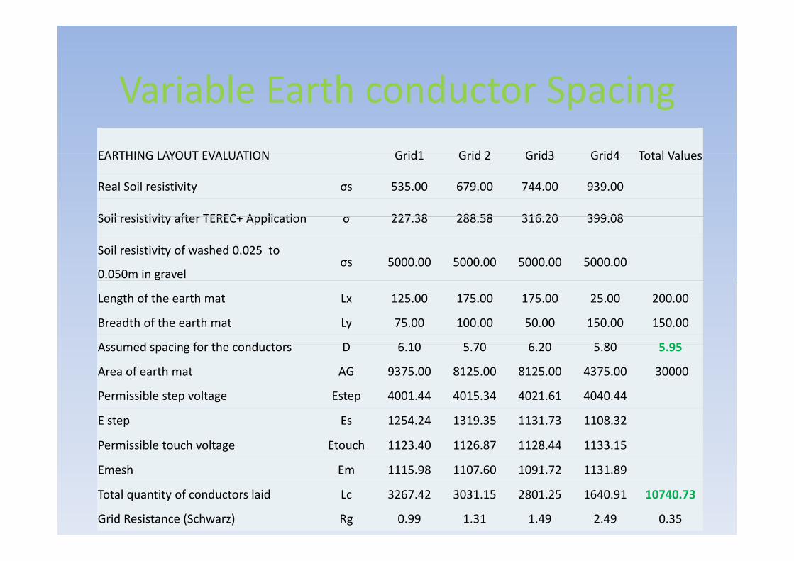
Variable Earth conductor SpacingVariable Earth conductor SpacingEARTHING LAYOUT EVALUATION G id1 G id 2 G id3 G id4 T t l V lEARTHING LAYOUT EVALUATION Grid1 Grid 2 Grid3 Grid4 Total Values
Real Soil resistivity σs 535.00 679.00 744.00 939.00
Soil resistivity after TEREC+ Application σ 227 38 288 58 316 20 399 08Soil resistivity after TEREC+ Application σ 227.38 288.58 316.20 399.08
Soil resistivity of washed 0.025 to
0.050m in gravelσs 5000.00 5000.00 5000.00 5000.00
Length of the earth mat Lx 125.00 175.00 175.00 25.00 200.00
Breadth of the earth mat Ly 75.00 100.00 50.00 150.00 150.00
A d i f th d t D 6 10 5 70 6 20 5 80 5 95Assumed spacing for the conductors D 6.10 5.70 6.20 5.80 5.95
Area of earth mat AG 9375.00 8125.00 8125.00 4375.00 30000
Permissible step voltage Estep 4001.44 4015.34 4021.61 4040.44
E step Es 1254.24 1319.35 1131.73 1108.32
Permissible touch voltage Etouch 1123.40 1126.87 1128.44 1133.15
Emesh Em 1115 98 1107 60 1091 72 1131 89
safety thru design 14
Emesh Em 1115.98 1107.60 1091.72 1131.89
Total quantity of conductors laid Lc 3267.42 3031.15 2801.25 1640.91 10740.73
Grid Resistance (Schwarz) Rg 0.99 1.31 1.49 2.49 0.35
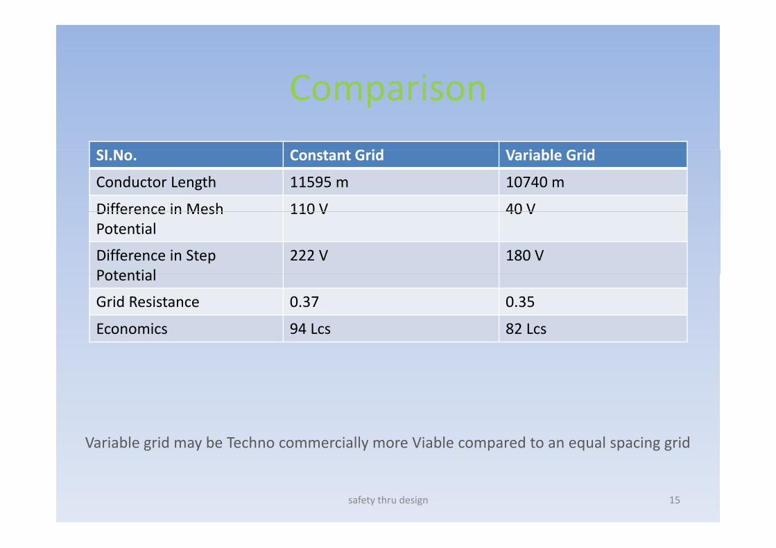
ComparisonComparison
S C G id i bl G idSI.No. Constant Grid Variable Grid
Conductor Length 11595 m 10740 m
Difference in Mesh 110 V 40 VDifference in Mesh Potential
110 V 40 V
Difference in StepPotential
222 V 180 VPotential
Grid Resistance 0.37 0.35
Economics 94 Lcs 82 Lcs
Variable grid may be Techno commercially more Viable compared to an equal spacing grid
safety thru design 15
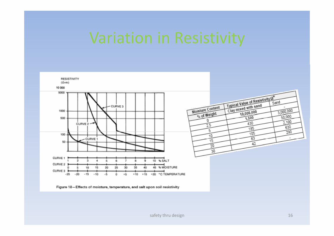
Variation in ResistivityVariation in Resistivity
safety thru design 16
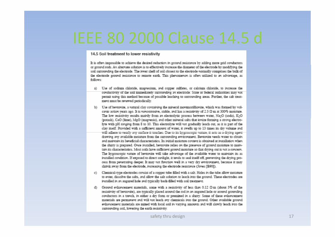
IEEE 80 2000 Clause 14 5 dIEEE 80 2000 Clause 14.5 d
safety thru design 17
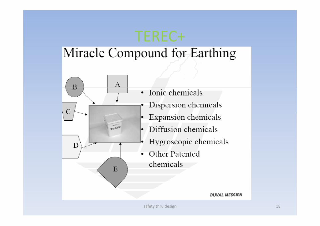
TEREC+TEREC+
safety thru design 18
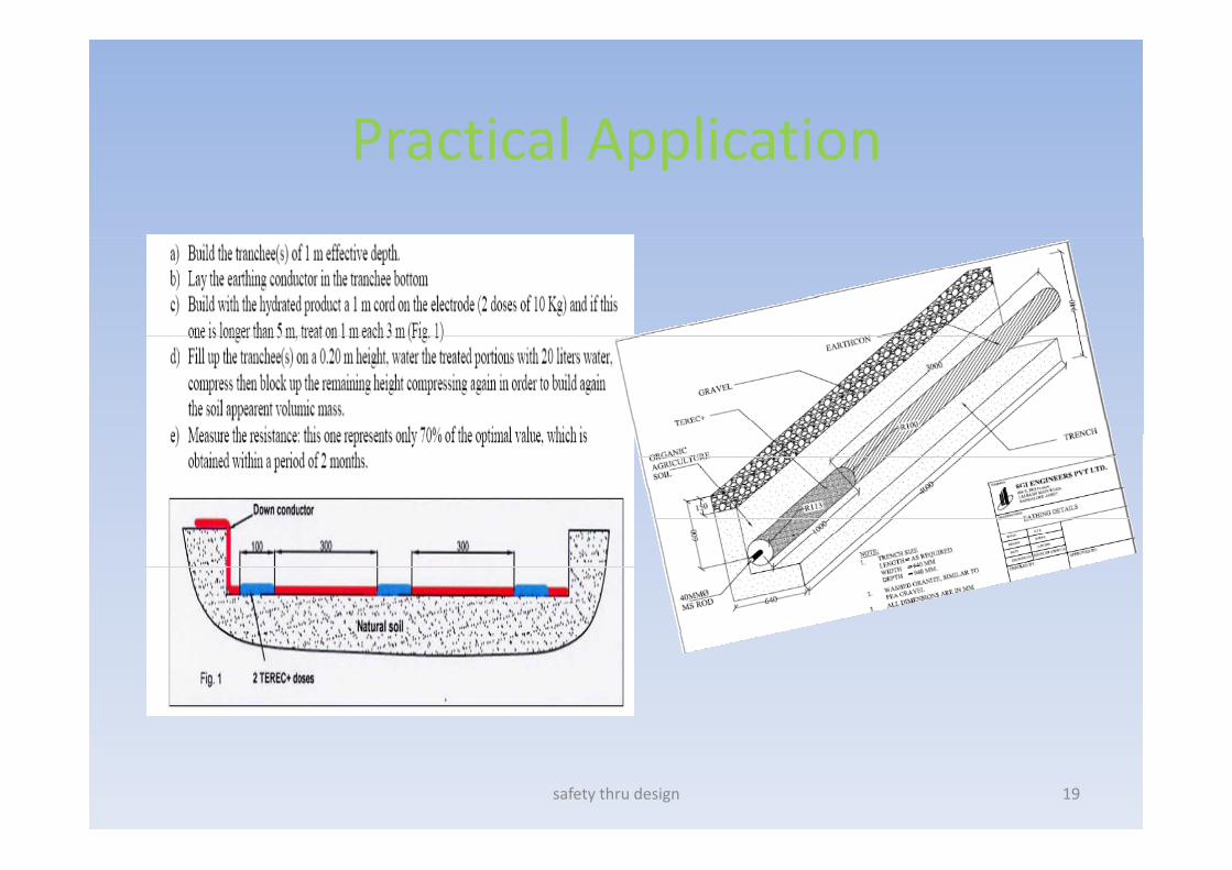
Practical ApplicationPractical Application
safety thru design 19

CPRI Stability ReportCPRI Stability Report
safety thru design 20
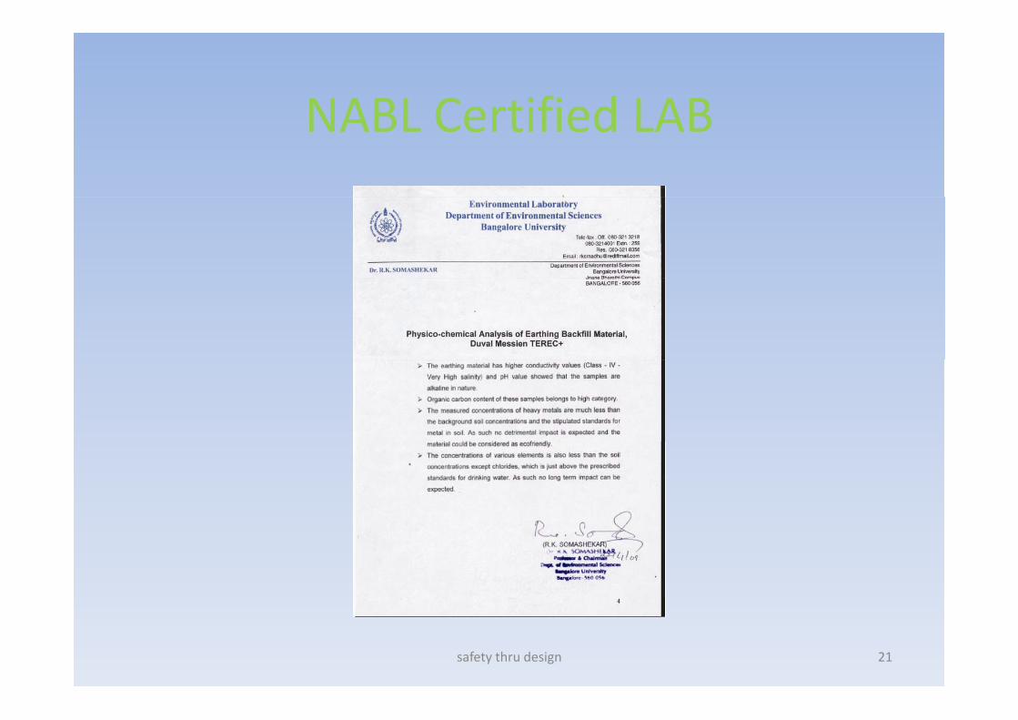
NABL Certified LABNABL Certified LAB
safety thru design 21
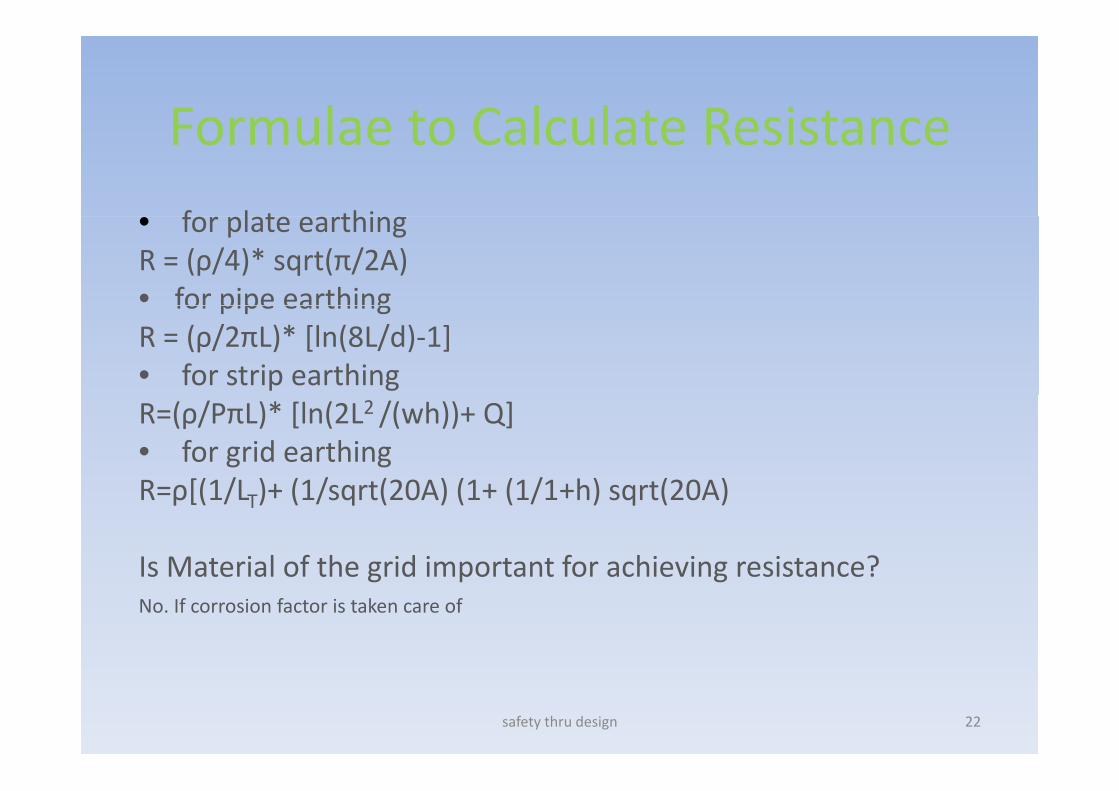
Formulae to Calculate ResistanceFormulae to Calculate Resistance
f l t thi• for plate earthingR = (ρ/4)* sqrt(π/2A) • for pipe earthingfor pipe earthingR = (ρ/2πL)* [ln(8L/d)‐1]• for strip earthingR=(ρ/PπL)* [ln(2L2 /(wh))+ Q]• for grid earthingR ρ[(1/L )+ (1/sqrt(20A) (1+ (1/1+h) sqrt(20A)R=ρ[(1/LT)+ (1/sqrt(20A) (1+ (1/1+h) sqrt(20A)
Is Material of the grid important for achieving resistance?Is Material of the grid important for achieving resistance?No. If corrosion factor is taken care of
safety thru design 22

Relook at Alternating CurrentRelook at Alternating Current
C i f• Current is not movement of charge or holes.
• In Alternating Current theIn Alternating Current, the charge actually does not travel at all. It only vibrates i i i iin its mean position.
• Across a Cross section area, the vibration begins withthe vibration begins with one charge and increases to the maximum number of h i if icharges signifying amplitude of the sinusoidal AC waveform.
safety thru design 23
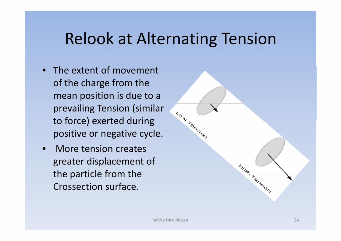
Relook at Alternating TensionRelook at Alternating Tension
• The extent of movement of the charge from the
iti i d tmean position is due to a prevailing Tension (similar to force) exerted duringto force) exerted during positive or negative cycle.
• More tension creates• More tension creates greater displacement of the particle from thethe particle from the Crossection surface.
safety thru design 24
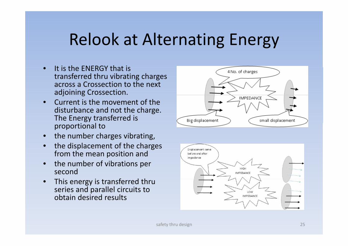
Relook at Alternating EnergyRelook at Alternating Energy• It is the ENERGY that is• It is the ENERGY that is
transferred thru vibrating charges across a Crossection to the next adjoining Crossection. j g
• Current is the movement of the disturbance and not the charge. The Energy transferred is
lproportional to • the number charges vibrating, • the displacement of the charges
f h i i dfrom the mean position and • the number of vibrations per
secondThi i f d h• This energy is transferred thru series and parallel circuits to obtain desired results
safety thru design 25
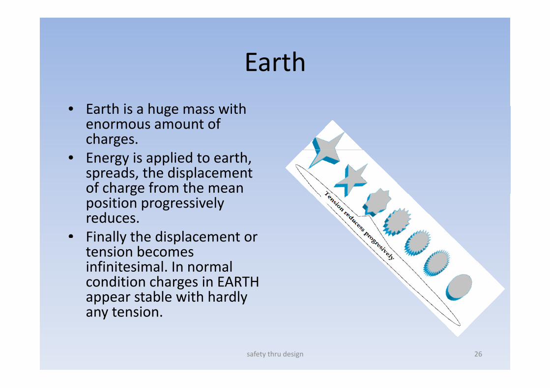
EarthEarth
E th i h ith• Earth is a huge mass with enormous amount of charges.
• Energy is applied to earth, spreads, the displacement of charge from the mean gposition progressively reduces.
• Finally the displacement orFinally the displacement or tension becomes infinitesimal. In normal condition charges in EARTHcondition charges in EARTH appear stable with hardly any tension.
safety thru design 26
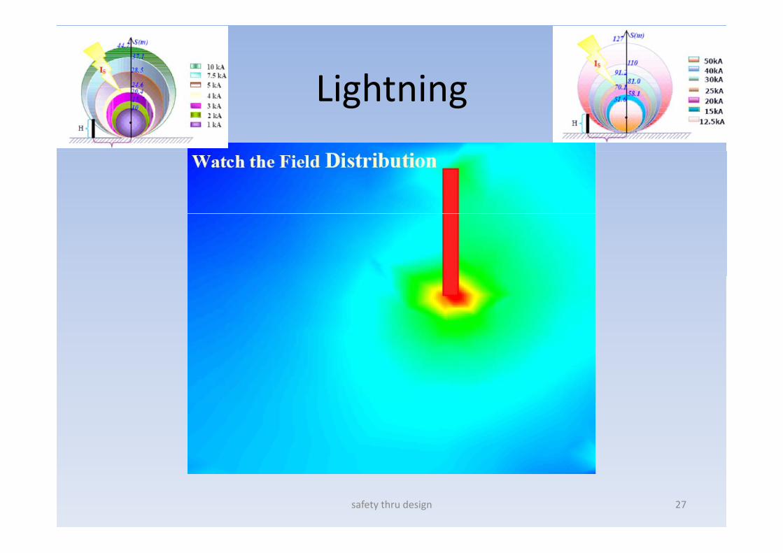
LightningLightning
safety thru design 27
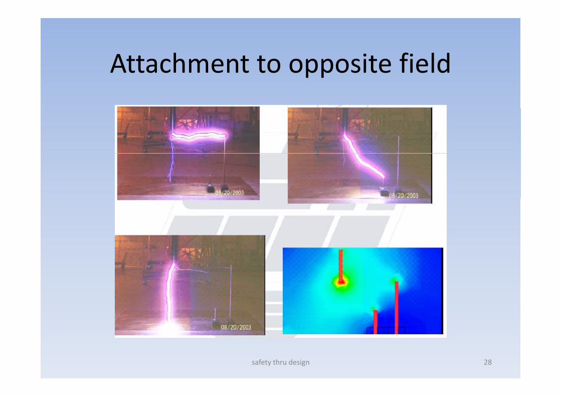
Attachment to opposite fieldAttachment to opposite field
safety thru design 28
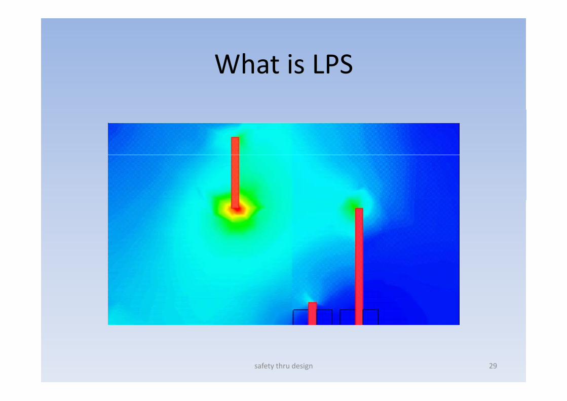
What is LPSWhat is LPS
safety thru design 29
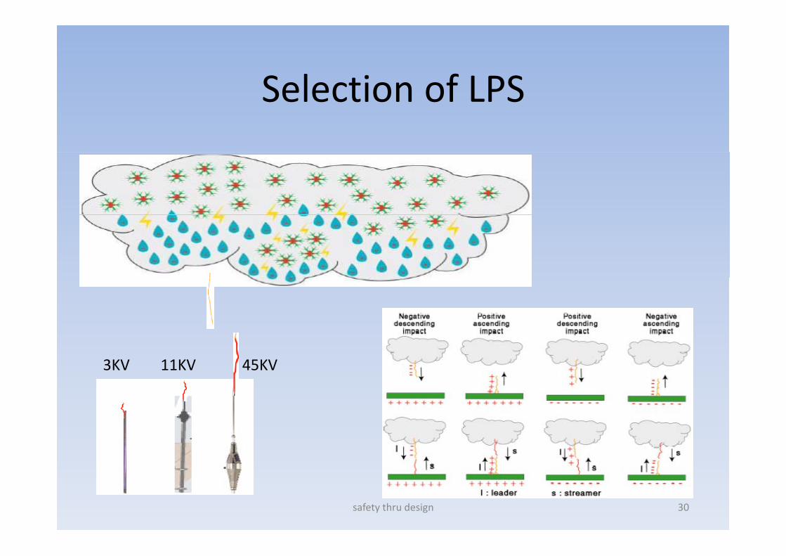
Selection of LPSSelection of LPS
3KV 11KV 45KV
safety thru design 30
safety thru design 31

Resistivity and PermittivityResistivity and Permittivity
safety thru design 32

Tackling Different FrequenciesTackling Different Frequencies
f d d• Dissipation of energy depends on Earth loop impedance.
• High frequency signals encounter g q y ghigh inductive impedance if the loop length is long. Hence the Ground path needs to be as shortGround path needs to be as short as physically possible.
• As ground is a dielectric, it is also d h l l d fgood to have a plate electrode for
higher displacement current.
• Higher frequencies do not enter g qdeep earth, hence it is imperative to have more number of shallow earthearth
• Use Earth Bondsafety thru design 33

Revisit your Earth GridRevisit your Earth Grid
D h th E th id d d b t• Do you have the Earth grid drg. and subsequent record of changes conducted in your premises
• Is Earth pit reading in the grid different at• Is Earth pit reading in the grid different at different places
• Has the Source increased• Has the Source increased• Has number of feeders or distributors changedA U b l d H i b i ti f• Are Unbalances and Harmonics been existing for a long time.
• Is off schedule maintenance a regular feature• Is off schedule maintenance a regular feature• GET YOUR SELF AUDITED
safety thru design 34

Who can be an AuditorWho can be an Auditor
• H i K l d f• Having Knowledge of – IEEE 80 2000 for substation– IEEE 665 1995 for Generating Station– IEEE 142 1991 for Industrial establishment
f h– IEEE 81 1993 for Earthing Measurements– IEEE 1100 for powering and grounding electronic equipments.– IEEE 575 for sheath bonding and induced voltages– BS 7340 1998 Code of practice for Earthing
IEC 62305 P t 1 t P t 4– IEC 62305 Part 1 to Part 4– NFPA 70 and NFPA 780– API RP 2003 for statics and lightning protection– And many more ref. textsH i R i it i t t h k it l t i t• Having Requisite equipments to check vital parameters using stray current filters.
• Has the desired National and International Experience to AuditRefineries– Refineries
– Power Stations etc.
• Should be a Solution providerpsafety thru design 35

Rejuvenation of Live gridRejuvenation of Live grid
safety thru design 36

Rejuvenation of live gridRejuvenation of live grid• Measure the soil resistivity with• Measure the soil resistivity with
– Stray current filter– Variable frequency
High and low current injection probe– High and low current injection probe• Make polar graph for accurate soil resistivity• Design the earth grid as per IEEE 80 2000 as if it was for the new grid
Th f f iti th it b l 1 7% f th f• The surface area of exiting earth pit may be only 1‐7% of the surface area of the entire Earth grid.
• May involve multiple layer/tier of peripheral correction. U i li d t i d t k li d t ti• Use specialized manpower trained to work on live yard or station
• New trenching can be very tedious. It may cut across existing HV, LV or control cablesAt th d f ti All th th it h ld h l t• At the end of correction, All the earth pits should have almost same resistance value without any pit correction
safety thru design 37
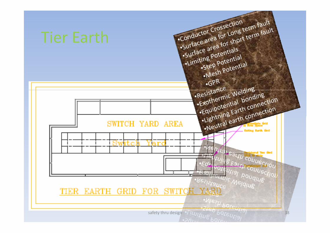
Tier EarthTier Earth
safety thru design 38

Proper and Permanent JointingProper and Permanent Jointing
safety thru design 39
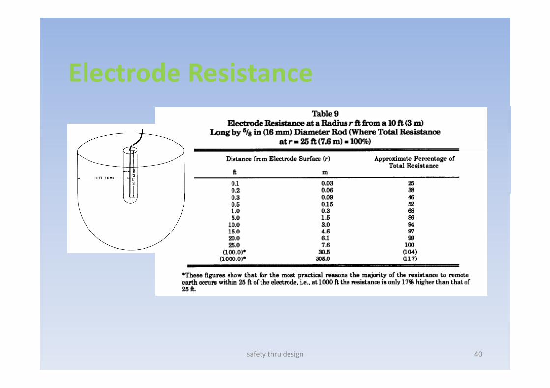
Electrode Resistance
safety thru design 40

Sigma EarthSigma Earth•The Energy after leaving the electrode encounters different k d f l h fl f lkinds of soil where reflection factor comes into play•Sigma earth ensures that artificial treatment compounds are laid in a specific geometric pattern to minimize the reflection•Thru proper calculation, can achieve less than 1 ohm in veryThru proper calculation, can achieve less than 1 ohm in very hard soil.•Used for Independent Electronic Earth or reference earth
safety thru design 41
Iris earthIris earth• One earth sensor is put inside an old• One earth sensor is put inside an old
or new pit.• Various parameters like date,
location, value etc are logged in every sensor.
• The sensor is programmed to alarm on few criteria’s.
• There is multiple level of alarm• There is multiple level of alarm.• A peripheral command center (PCC)
can talk to approximately 100 earth pits.
• A hand held tester is provided to check the earth pit conditions remotely
• The PCC can be locally connected to a• The PCC can be locally connected to a local Laptop and a remote Server on LAN or GSM.
safety thru design 42

Geomagnetic Storms caused by Solar Flares or CME
• Earth’s magnetic field beingpushed out of the way by thenuclear explosion or solar stormf ffollowed by the field being restoredto its natural place.•This process can produce geo‐magnetically induced currents inlong electrical conductors (likepower lines) which can damage ord l fdestroy power line transformers.
safety thru design 43
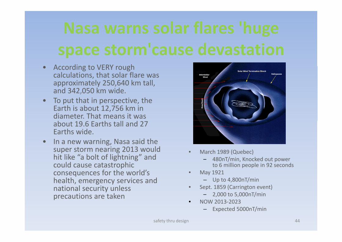
Nasa warns solar flares 'huge space storm'cause devastation
• According to VERY rough• According to VERY rough calculations, that solar flare was approximately 250,640 km tall, and 342,050 km wide. ,
• To put that in perspective, the Earth is about 12,756 km in diameter. That means it was b h ll dabout 19.6 Earths tall and 27 Earths wide.
• In a new warning, Nasa said the super storm nearing 2013 wouldsuper storm nearing 2013 would hit like “a bolt of lightning” and could cause catastrophic consequences for the world’s
• March 1989 (Quebec)– 480nT/min, Knocked out power
to 6 million people in 92 seconds• May 1921q
health, emergency services and national security unless precautions are taken
– Up to 4,800nT/min• Sept. 1859 (Carrington event)
– 2,000 to 5,000nT/min• NOW 2013‐2023
safety thru design 44
NOW 2013 2023– Expected 5000nT/min
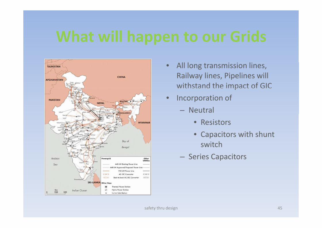
What will happen to our GridsWhat will happen to our Grids
• All long transmission lines, Railway lines, Pipelines will withstand the impact of GICwithstand the impact of GIC
• Incorporation of
– Neutral
• Resistors
• Capacitors with shunt switch
– Series Capacitors
safety thru design 45
Operational SolutionOperational Solution
• Build command and control centre to receive satellite data in to initiate requisite action. We have approximately 60 ‐90 min to initiate and complete operational procedures including discharginginitiate and complete operational procedures including discharging
• Break down the power system into small islands and earth the surge created using automated star point switch connections and disconnections.
• Creating an efficient maintenance free and monitorable earthing systemsystem
• Predicting static accumulations, and BMS enabled lightning protection systemp y
• The entire infrastructure needs to be grounded as much as 'possible without forming Earth loops
It is Either Now Or Never
WE ARE RESPONSIBLEIt is Either Now Or Never
safety thru design 47
Top Related