


Idiomas
Páginas
Jurídico

SEP DGETI SEIT
CENTRO NACIONAL DE ACTUALIZACI~N DOCENTE EN MECATRÓNICA
,
CNAD - Cenidet
PROYECTO
MODELO DE FÁBRICA AUTOMATIZADA (FA)
Prototipo Mecatrónico
Que Presentan: Para obtener el reconocimiento de especialista en Ingeniería Mecatrónica.
AREA DE MAQUINAS: AREA ,DE CONTROL: '
Ing. Javier Eucario Rivera Vivas Téc. Francisco Arvizu Conde
Téc. Mahue1 G. Méndez Monforte. '
Ing. Salvador Moreno Sosa.
ASESORES: Máquinas : Lic. Arcadio Garcia Melchor Control : Ing. Natividad Rodriguez Montoya
Diciembre 2000
k o 1 - 0.5 3 4 ¡I

C N I D D G E T I Mecatrónica Centro Nacional de
Actualización Docente C109FMP00010
!
Mexico, D.F. 3 de agosto de 2001. ASUNTO: Autorización de irnpiesión
del trabajo recepcional.
C.C. Francisco Arvizu Conde Javier Rivera Vivas Salvador Moreno Sosa Manuel Monforte Méndez P R E S E N T E S
Una vez que se ha revisado el informe academic0 elaborado como trabajo recepcional del proyecto Mecatrónico titulado "M8delo de Fabrica Automatizada" por los asesores de las dos áreas y al no encontrar errores en los aspectos tecnicos, en la estructura de contenidos y en la redacción cada una de los apartados que lo integran, se ha determinado que el informe cumple con los aspectos técnicos necesarios para que pueda imprimirse de forma definitiva. ,
A T E N T A M E N T E
Lic. &dio Garcia Melchor AREA DE MAQUINAS
ASESORES
Ina. .17 Natividad Montoya I
ÁREA DE CbNTROL .

AGRADECIMIENTOS
Los integrantes del equipo 5 (Francisco Arvizu Conde, Javier Rivera Vivas, Salvador Moreno Sosa y Manuel Monforte Mendez) del Área de Máquinas y control respectivamente agradecemos al Lic. Arcddio Garcia Melchor (del Área de Máquinas) y al Ing. Natividad Rodriguez Montoya (del Área de Control), las observaciones y sugerencias que hicieron a los distintos manuscritos que se elaboraron para llegar al reporte técnico final que aquí presentamos.
También queremos hacer patente nuestro agradecimiento al Ing. Filiberio García Cerecedo, Jefe del Área de Máquinas por suldesinteresada asesoría en la elaboración e impresión de los dibujos que forman parte del proyecto modelo de Fabrica Automatizada.
AI Ing. Alejandro González Mata, Subdirector ,¡Técnico del CNAD, por su comprensión y apoyo para la realización de este proyecto y a todos aquellos profesores que de una u otra forma contribuyeron para la realización del mismo.
' \
i
i

íNDlCE
PORTADA AGRADECIMIENTOS ....................................................................................... INDICE .............................................................................................................
JUSTIFICACI~N .............................................................................................. INTRODUCCION .............................................................................................. OBJETIVOS b .....................................................................................................
1 DESCRIPCIÓN GENERAL DEL SISTEMA ............................................... 1.1 Dibujo general del prototipo ...................... .............................. 1.2 Diagrama a bloques de los elementos del sistema ........................ 1.3 Descripción Y diagrama de flujo del funcionamiento ..............................
DESCRIPCIÓN DEL SiSTEMA MECÁNICO ............................................. 2.1 Descripción y dibujos de los elementos mecánicos ............. 2.2 Cálculos de los elementos y mecanismos ....... I ..................................... 2.3 Descripción de los procesos de fabricación de los elementos
mecanicos ....................................... ...................................................
DESCRIPCIÓN DEL SISTEMA DE CONTROL ........................................ 3.1 Diagrama a bloques y descripción del sistema de control ................... 3.2 Descripción de los elementos del sistema .......
3.2.1 Elementos de entrada .............................. 3.2.2 Elementos de salida ............................................................. 3.2.3 Controlador ........................ .....................................
3.3 Esquemas y tarjetas de circuito impreso (PCB) ..................................
4 INTEGRACION DEL SISTEMA MECATRÓNICO .....................................
'I
2
, .
3
.............
..............
............. 4.1 Programación .......................... ..........................
4.2 Operación del prototipo ......................... .................... 4.3 Calibración y aju .............. 4.4 Mantenimiento ... ........................
LISTA DE MATERIALES Y COSTO ..........................................................
.............. 4.1 .I Diagrama de flujo ....... 4 1.2 Programa de control d
.............................. ...................
........................
5
i ii iii iv V
1
9 13
26
29
29 44 44 47 48 54
77
77 77 88
114 114 115
117
5.1 Sistema de control ................................................................................ 117
5.2 Sistema mecanlco ............................................................................... 122 , .
ii

6 CRONOGRAMA DE ACTIVIDADES ............... i ......................................... 126
6.1 Area de maquinas ................................................................................ 126 6.2 Area de control .....................................................................................
127 7 CONCLUSIONES Y RECOMENDACIONES .............................................. 128
8 APENDICES ............................................................................................... "130
. .
9 BIBLIOGRAF~A .......................................................................................... 133

INTRODUCCIÓN
El presente infOrme técnico resetia cada uno de 10s procesos que se realiiaron para el diseno, COnStrUCCiÓn, ensamble y operación de 10s mecanismos que forman el modelo de Fábrica Automatizada (FA.). Tanto en el aspecto mecánico como en el aspecto eleCtrÓniC0 y de control; además se presenta la lista de materiales que Se Utiiizaron para la construcción/ de 10s distintos mecanismos e incluye 10s costos de fabricación de los mismos yiun cronograma que muestra la planeación y control de las distintas actividades que se realizaron para la construcción del citado prototipo.
El informe se desarrolla de la siguiente manera:
En el primer capitulo se presenta una explicación general de cada uno de. los mecanismos que integran el modelo de Fábrica AStomatizada. Con un diagrama de bloques se muestra la relación que existe entre cada uno de los elementos que integran el F.A. y el funcionamiento se describe con la ayuda de un diagrama de flujo.
El capitulo dos detalla cada uno de los elementos que forman el sistema mecánico; señala cada una de las partes que forman el mecanismo, así como los cálculos que orientaron al diseño del mismo y la manera en que cada mecanismo fue fabricado.
El capitulo tres interpreta el sistema de control, con ,un diagrama de bloques que incluye los elementos de entrada y salida; así como, los esquemas y tarjetas de circuito impreso que forman el sistema de control.
El capítulo cuatro expone los distintos programas (de cómputo y PLC) que permiten manipular el prototipo en forma automática, la calibración, ajustes, mantenimiento y la forma de operación manual del equipo.
El capitulo cinco glosa el costo de cada uno de los materiales que integran el prototipo, tanto del sistema de control como del mecá!ico.
El penúltimo capitulo versa sobre el cronograma de adtividades que se utilizo para el desarrollo del sistema tanto del área de máquinas c imo del área de control.
y finalmente se tratan las conclusiones que se obtuvieron al fabricar este modelo y las recomendaciones pertinentes al caso.
I
'
iii
OBJETIVOS
Fabricar un prototipo didáctico-mecatrónico (Modelo de Fábrica Automatizada) que invoiucre conocimientos teórico-prácticos de máq&nas y control.
Disenar y construir los mecanismos que componen el prototipo didáctico (almacén de materia prima, almacén de producto terminado, estación de taladrado, alimentador de banda, banda transportadora, pinza sujetadora, mesa giratoria y brazo manipulador).
Determinar los tipos de motores que se utilizarán para otorgar el movimiento,a la mesa giratoria, al brazo manipulador, al taladro y la'banda transportadora.
Determinar los tipos de sensores que se usarán ,para detectar la presencia de aluminio, hierro y madera.
Construir las tarjetas necesarias para controlar las distintos actuadores
Fabricar las fuentes de alimentación requeridas para cada actuador.
iV

JUSTIFICACI~N
El avance tecnológico que observamos hacia \fines del presente milenio, el desarrollo de los procesos industriales, el tratado de libre comercio y la globalización de la economía, exigen que para seguir siendo una nación próspera, soberana e independiente que garantice una posición digna de Mexico entre las naciones, se requiere emprender o continuar acciones que propicien que el pais continúe su desarrollo al ritmo de estos cambios. ’
Los procesos industriales tradicionales requerirán de técnicos especializados en disciplinas independientes como la mecánica, la electrónica, el control y la computación entre otras.
Con el desarrollo de nuevos procesos productivos más eficientes y de mejor calidad, surgen sistemas, maquinaria y equipo que son el resultado de la integración de varias disciplinas del conocimiento, con lo que existe la necesidad de personal más especializado en varias disciplinas.,
El desarrollo tecnológico en la actualidad requiere side profesionales capaces de diseñar, fabricar y dar mantenimiento a equipo y ma.quinaria automatizada. Por lo expuesto y por la necesidad de formar recursos humanos en áreas tecnológicas estratégicas, la Dirección General de Educación Tecnológica Industrial a través del C.N.A.D., forma y capacita docentes en la especialidad de Mecatrónica y ante la falta de equipamiento en los planteles del Subsistema para el Bachillerato Tecnológico en Mecatrónica, se presenta el prototipo denominado “Modelo de Fábrica Automatizada” que será utilizado en las escuelas que cuenten con el Bachillerato Tecnológico en Mecatrónica; mismo qhe servirá para utilizarse en algunas de las asignaturas tecnológicas que confohan el plan de estudios del citado bachillerato.
El prototipo en cuestión es un recurso didáctico para los planteles dependientes de la D.G.E.T.I. y sime para explicar de manera objetiva temas relacionados con la Mecánica, Electrónica, Neumática, y Control, facilitando .! el aprendizaje de los alumnos.
V
1 DESCRIPCI~N GENERAL DEL SISTEMA. ' i
1.1 Dibujo general del prototipo,
El modelo de "Fabrica Automatizada" (FA)l es un sistema integrado por elementos mecánicos y electrónicos que Permiten simular la producción automatizada a escala industrial.
El prototipo se integra de los siguientes elementos mecánicos:
1.- Un gabinete de lámina negra que sirve para soportar los elementos.que
2.-Una banda transportadora, que sirve para trasladar cubos de 25.4mm de lado, que es la materia prima y su acciona,miento se hace por un motor eléctrico de corriente continua.
intervienen en el sistema. 'I
3.-Unidad de mantenimiento es una estructura metálica que permite soportar un filtro de aire con regulador de presión para!!alimentar a los componentes neumáticos del sistema.
4.417 brazo manipulador de tres grados de libertad (movimiento rotatorio, movimiento vertical y movimiento horizontal), accionado por un motor eléctrico que proporciona el movimiento giratorio. El movimiento vertical se produce por un motor eléctrico, acoplado a un husillo y una tuerca embalada, de tal forma que permite el ascenso o descenso del elemento sujetador con solo cambiar el giro del motor. El movimiento Uorizontal es producido por un cilindro neumático de tipo antigiro, el cual porta una pinza sujetadora. La apertura de la pinza sujetadora es realizada por un cilindro neumático de simple efecto y el cierre se realiza por medio de un resorte de tipo helicoidal con lo que se sostiene el cubo de metal, madera o aluminio.
!
. - . . . .
5.- Una mesa circular que permite mover al brazo manipulador en forma giratoria, en sentido de las manecillas del reloj o:en contra.
6.-Una estación de taladrado, para simular dicho proceso en piezas que cumplan con características y condiciones especificadas previamente. El taladrado será simulado mediante el funcionamiento de un broquero accionado por un motor eléctrico y el ascenso y descenso del mismo será por un cilindro neumático de tipo antigiro. La estación cuenta con un mecanismo neumático que permite sujetar la pieza a procesa'r.
7.- Dos estructuras metálicas que simulan los almacenes de materia prima y producto terminado, Cada estructura tiene tres niveles de almacenamiento, en donde se ubican los materiales que integran la materia prima o el producto terminado.

8.- Un mecanismo que permite abastecer a la banda transportadora con la materia prima a procesar. Dicho mecanismo es accionado por un cilindro neumático.
El siguiente dibujo identificado como No. FA, muestra la estructura general del prototipo y señala con un número cada uno de los elementos descritos anteriormente.
2

I 2 3
G a b i n e l e m e t a l i i o R a n d a i r a n s p o r t a d o r a U n i d a d d e m a n l e n i m i e n t o
16 / U n i d a d de t a l a d r a d o - 1
4
5
I
ü r a z o m a n i p u l a d o r y p i n z a s u j e i M e s a c i r c u l o r g i r a t o r i a
I I E n s a m b I e V a r 1 0 s
P a r t e 1 C a n t i d a d D e s i g n a c i o n M a i e r i a l
e c h a : 15/12/00 CENTRO NACIONAL DE e í e r e n c ¡ a : ACTUALlZAClON DOCENTE
c o t . : mm M O D E L O D E F A B R i C A E l c . : A U T O M A T I Z A D A
1 O b s e r va( I o n e s
P,oy I n g , J o i i r r R I I C I P Yiial
b i b . i n ? J o t i t r R i i r r o V i r a l
R r i L i c . A r t a d i o G o r ( i a Y I l l h 8
No, FA

1.2 Diagrama de bloques de los elementos del sistema
El siguiente diagrama de bloques muestra la distribución de los elementos mecánicos que forman el FA.
producto terminado r
[Unidad de I W mantenimien manipulador
IAlmacende 1 Almacen de Estación de Almacén de materia taladrado producto prima terminado
mantenimien manipulador
Alimentador
/
Banda transportadora
Las flechas indican el sentido en que se transpoda la materia prima. en cada etapa del proceso.
Cuando la materia prima es detectada por los sensores que se encuentran en cada uno de los niveles del almacén (de materia prima), esta es transportada al alimentador de la banda por medio del brazo manipulador.
Una vez colocada la materia prima en el alimentador, ésta se traslada al inicio de la banda transportadora por la acción del alimentador, el cual deposita la pieza sobre la banda transportadora.

*I estar la Pieza sobre la banda transportadora, se activa el motor eléctrico que permite lkvar la pieza al final de la badda y durante el traslado, la.pieZa pasa debajo de dos Censores, Uno refleXiVO_y otro de proximidad, quienes se encargan de detectar el.tipo de material que se está procesando en ese rnOment0. La banda se detiene por la setial que envía un limit Switch ubicado al final de la banda y que es accionado por la pieza en cuestión.
En ese momento el sistema ha detectado la clase de material y entonces se tienen las condiciones necesarias que permiten llevar la pieza al almacén de producto terminado o a la estación de taladrado.'
Si la materia prima es madera, ésta será 'transportada a la estación de taladrado, donde se simulará el proceso e inmediatamente después se enviará al almacén de producto terminado. Una vez depositada la pieza en la mesa de trabajo, de la unidad de taladrado, se activa un cilindro neumático el cual permite mover el mecanismo que sirve para sujetar la pieza y en ese momento se gira el broquero, bespués se hace descender el sistema de barrenado, para simular el proceso, concluida la operación se retrae el cilindro, se para el motor del broquero, se desactiva el cilindro sujetador y se procede a transportar la pieza al almacén de producto terminado.
almacén de producto terminado recibe las piezas provenientes de la torre de taladrado 0 del final de la banda, Siempre y cuando 10s SenSOreS ubicados en el almacén de producto terminado reporten espacios disponibles.
'I
1.3 Descripción Y diagrama de flujo del funcionamiento.
EI FA opera en tres modalidades que Son manual, PLC Y pc
La operación manual se realiza al seleccionar la modalidad correspondiente, la cual permite controlar cada uno de los mecanismos mediante la operación de botones.
AI elegir la opción PLC, se deberán conectar los cables de entradas y salidas del PLC a los bornes de la parte front,al del FA para controlar los mecanismos mediante un programa de PLC.
El FA también cuenta con un conector en la parte frontal, que permite conectarse a un puerto de salida de la computadora (PC) y así poder controlar los diferentes mecanismos con un programa hecho en "C", visual- basic, pascal o cualquier otro lenguaje de programación.
0
5

La forma en. que opera es muy sencilla, :.primero se energiza el equipo presionando el botón correspondiente, después se elige con el selector la forma de operación que se desee ( manual, PC y PLC).
Si se elige la opción manual ésta permitirá:
Mover la mesa giratoria en el sentido de las manecillas del reloj (CW) o en contra (CCW), hasta llegar a tocar un limit switch (desactiva el funcionamiento del motor) que se encuentra: colocado sobre la cubierta del gabinete, el cual es accionado por un perro de arrastre que se encuentra sobre la mesa giratoria.
* Deslizar el brazo manipulador hacia arriba o, hacia abajo, al frente o atrás. Dichos movimientos están restringidos por los limit switchs que se ubican sobre la estructura del brazo manipulador en la parte superior y la inferior. Un cilindro neumático de tipo antigiro, que al accjonarse produce el movimiento de extracción (hacia el frente) o retracción (hacia atrás)
* Abrir o cerrar la pinza sujetadora (garra). La apertura se efectúa por la acción de un cilindro neumático de simple efecto y la acción de un resorte de , ' tipo helicoidal que permiten el cierre de la pinza.
.F Subir o bajar el taladro (activación de un cilindro neumático de tipo antigiro). arrancar o parar el motor del broquero, abrir o cerrar el mecanismo sujetador de la pieza (activación por un cilindro neumático),
Mover el alimentador de la banda hacia el frente o atrás (con un cilindro neumático)
'
+ Accionar o parar el motor de la banda.
Es decir en forma manual se podrán realizar todas ,las operaciones del FA
Las opciones de PC y PLC hacen lo mismo que la operación manual solo que estas dos opciones lo hacen en forma automatizada (se indican previamente los movimientos), a través del programa de PC o de PLC.
La simulación del proceso de fabrica automatizada consiste en lo siguiente:
1.- Se deposita la materia prima (cubos de 25 mm de lado, en madera aluminio y acero AIS11018) en cada uno de los niveles del almacén de materia prima.
6

2.- El brazo manipulador Se encuentra en Ia'Iposición final de la banda. L~~ Sensores detectan la presencia de dichos ::materiales, en ése momento se envia una setial que permite activar el motor de la mesa giratoria en el sentido horario (CW) hasta situarse frente al almacén de materia prima donde se encuentra el cubo que puede ser madera, hierro y aluminio.
3.- Se activa el cilindro neumático para abrir la pinza sujetadora y enseguida el cilindro neumático de desplazamiento horizontal, para colocarse en posición
4.- Se efectúa el cierre de la garra, se retrae el cilindro sujetando la pieza y se inicia el giro de la mesa en sentido de las manecillas del reloj, para llevar la pieza frente al alimentador de banda, donde suelta la pieza y se retrae el cilindro antigiro; una vez alejada la pinza sujetadora se activa el alimentador, empujando la pieza para colocarla en el centro de la banda transportadora.
I
de sujetar la pieza. I!
5.- En ese momento inicia el funcionamiento del motor de la banda, con lo que la pieza pasa por dos sensores. uno de proximidad y otro reflexivos, 'los cuales envian las setiales correspondientes;I(al programa de computo o PLC) para su análisis y efectuar el siguiente proceso. Cuando la materia prima llega al punto final de la banda, el motor: de la banda se detiene por la señal que recibe del limit switch que es activado por la pieza que se esta transportando. En ése momento se activa el motor de la mesa giratoria en contra de las manecillas del reloj (CCW), para ubicarse frente a la posición final de la banda transportadora, después, 'se realizan los movimientos similares a los del inicio del proceso y 'continuar con la operación automatizada dependiendo de las caracteristicas del material; si es hierro o aluminio se lleva el cubo al nivel desocupado del almacén de producto terminado y si es madera el brazo manipulador lleva la pieza frente a la estacion de taladrado por un movimiento vertical descendente (dependiendo del nivel donde tomo la pieza) y al estar sobre la mesa de taladrado se abre la pinza para depositar la pieza, se retrae el cilindro en forma horizontal, una vez depositada la pieza y el cilindro retraido se acciona el cilindro que permite sujetar la pieza, bespués se acciona el motor del taladro, en seguida el cilindro antigiro que permite descender el taladro para simular el proceso de barrenado; acto seguido se retrae el cilindro del taladro, el motor del taladro se detiene y se desactiva el cilindro sujetador; después el cilindro neumático efectúa la apertuia de la pinza y se desliza en forma horizontal hasta la posición de sujeción d$ la pieza, se cierra la pinza, se retrae con la pieza y se gira la mesa hasta ubicarse frente al almacén de producto terminado y dependiendo del nivel que se encuentre vacio se efectuará un movimiento vertical para quedar frente al nivel vacio y proceder a depositar la pieza mediante el deslizamiento horizontal del brazo manipulador y una vez ubicada en la posición &recta se abre la pinza para
I
7

soltar la pieza, y efectuar la retracción y repetir el proceso descrito hasta que ya no existan piezas en el almacén de ;materia prima.
Cabe hacer mención que el proceso descrito no es único, sino que se pueden realizar distintas operaciones, Únicamente hay que definirlas y programarlas.
El siguiente diagrama de flujo muestra el funcionamiento del FA según lo ya descrito.
&+o HAY hlP
NO NO
> NIVEL 2
1 'MOVERSE AL NIVEL Y TOMAR PIEZA
MOVERSE AL ALIMENTADOR i DEJAR PIELA
NO
ALUMINIO
d/ TOhlAR Y LLEVAR PlEZh A ALM4CEN
T
8

2. DESCRIPCIÓN DEL SISTEMA MECÁNICO '
2.1 Descripción y dibujos de íos elementos mecánicos
Número consecutivo
1 2 3 4 5 6 7
I 8
La siguiente tabla muestra la relación de dibujos que se encuentran en el apéndice A, de los mecanismos que integran el Modelo de Fábrica Automatizada.
Nombre Identificación I
Pinza Sujetadora No. PS Brazo Manipulador No. BM Unidad de Mantenimiento No. UM Banda Transportadora No. BT Mesa Giratoria No. MG
No. TT Unidad de Taladrado No. AB Alimentador de Banda
Almacenes de Materia Prima v Producto No. A-MP-PT 1 Terminado
Es importante notar que despupés de cada dibujo del mecanismo le siguen los dibujos de las partes que integran cada mecanismo, y estos tienen las medidas a las que se fabricaron para su correcto ensamble!
A continuación se describen brevemente cada uno,de los dibujos
Pinza sujetadora. Este mecanismo se compone de)los siguientes elementos:
El soporte permite acoplar el mecanismo al cilindro antigiro, el cual sirve para realizar el movimiento horizontal de extraclión o retracción de la Pinza.
Los dedos sirven para sostener los' cubos de 25mm de lado (materia prima).
Los brazos permiten el movimiento de apertura 6 cierre de los dedos,
La cubierta superior e inferior permiten darle guerpo al mecanismo y ahí también se encuentra un pequeno cilindro neumatico que al activarse sale el vástago y vence la fuerza de un resorte helicoidal, ocasionando que los dedos de la pinza se abran y cuando se desactiva el cilindro, el vástago se retrae y con la ayuda del resorte se sujeta la pieia que se esta manipulando.
Existen otros elementos que no se incluyen debido a que son elementos complementarios muy importantes pero que nó se presentan por su fácil fabricación o por que son partes mecánicas lque se encuentran en el mercado, como son tornillos, tuercas, arandelas, 'resorte, bujes etc.
9
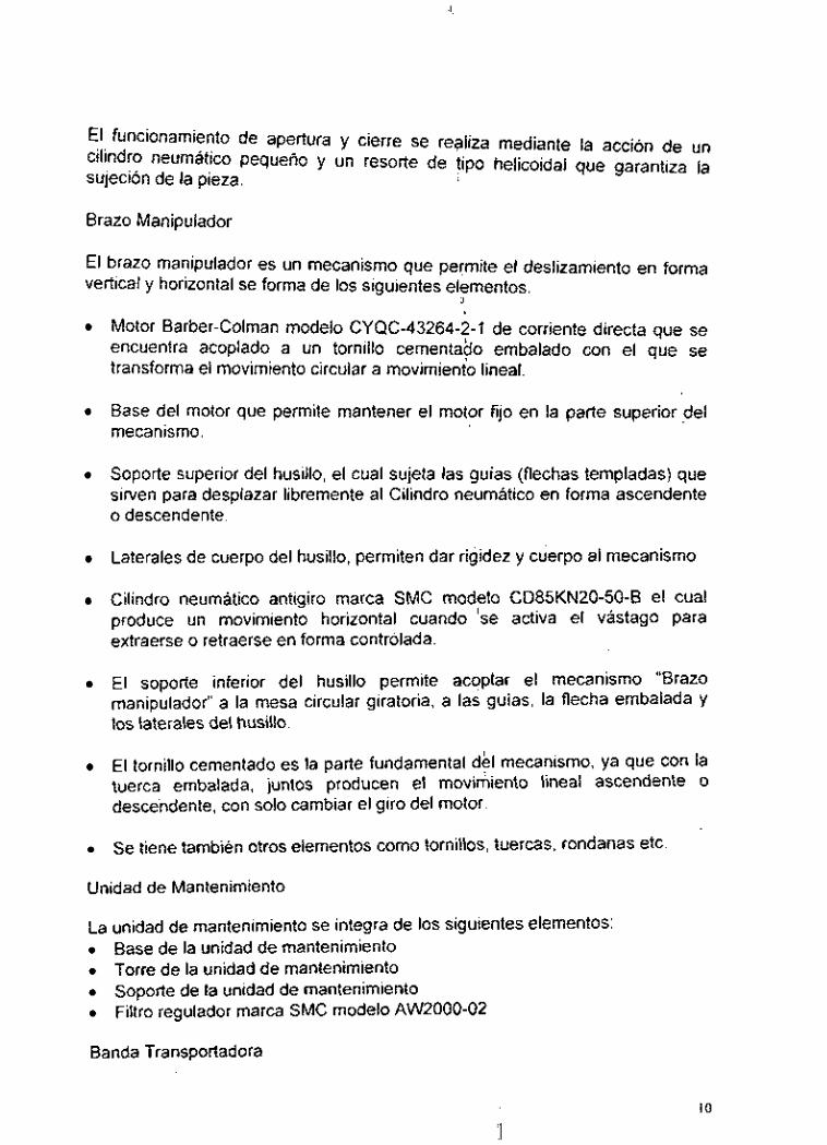
El funcionamiento de apertura y cierre se realiza mediante la acción de un cilindro neumático pequeño y un resorte de tipo helicoidal que garantiza la sujeción de la pieza.
Brazo Manipulador
El brazo manipulador es un mecanismo que permite el deslizamiento en forma vertical y horizontal se forma de los siguientes elementos.
:\
Motor Barber-Colman modelo CYQC-43264-2-1 de corriente directa que se encuentra acoplado a un tornillo cementa80 embalado con el que se transforma el movimiento circular a movimienio lineal.
Base del motor que permite mantener el motor fijo en la parte superior del mecanismo. I
Soporte superior del husillo, el cual sujeta las guías (flechas templadas) que sirven para desplazar libremente al Cilindro neumático en forma ascendente o descendente.
Laterales de cuerpo del husillo, permiten dar rigidez y cuerpo al mecanismo
Cilindro neumatico antigiro marca SMC modelo CD85KN20-50-6 el cual produce un movimiento horizontal cuando 'se activa el vástago para extraerse o retraerse en forma controlada.
El soporte inferior del husillo permite aco,plar el mecanismo "Brazo manipulador" a la mesa circular giratoria, a las: guías, la flecha embalada y los laterales del husillo.
El tornillo cementado es la parte fundamental del mecanismo, ya que con la tuerca embalada, juntos producen el movimiento lineal ascendente o descendente, con solo cambiar el giro del motor.
Se tiene tambien otros elementos como tornillos', tuercas, rondanas etc
Unidad de Mantenimiento
La unidad de mantenimiento se integra de los siguientes elementos: Base de la unidad de mantenimiento Torre de la unidad de mantenimiento Soporte de la unidad de mantenimiento Filtro regulador marca SMC modelo AW2000-02
Banda Transportadora
IO

Las bandas planas transportadoras son elementos importantes del tipo de eslabones mecánicos denominados "no rígido&" o "flexibles", ya que su forma cambia durante el movimiento. Este tipo de elementos se adapta para transmitir fuerza de tracción, pero no son capaces de':transmitir un empuje, es decir, pueden jalar pero no pueden empujar. En el &ototipo se decidió emplear una banda transportadora tipo plana como elementb de transmisión de movimiento lineal para el transporte de los cubos que es la materia prima que se utiliza en el modelo de Fabrica Automatizada. En este mecanismo se utiliza un motor eléctrico de corriente directa ( 12V CD) como elemento motriz, el cual acciona directamente a una polea o rodillo que a su vez/le proporciona movimiento a la banda transportadora, en conjunto con otra polea conducida-tensora y un rodillo loco que sirve para compensar la holgura.
La banda transportadora de nuestro prototipo está integrada de los siguientes elementos
'!
Soporte de la banda. Este se utiliza para fijar la banda al gabinete Caras laterales de la banda. Sirven para dar la estructura al mecanismo. Rodillo loco. Sirve para que junto con los tensores la banda se pueda tensar correctamente. Motor Barber Colman. Este motor permite ,girar la banda originando el movimiento lineal requerido para mover las piezas. Caja de balero. Soporta los baleros en donde giran los ejes del rodillo motriz y también del rodillo inducido. Separador de banda. Permite mantener la distancia de los laterales a una deterrninada distancia sin que afecte el dovimiento de la banda de poliuretano. Rodillo motriz. Es un acoplamiento entre el motor y la banda para transmitir el movimiento producido por el motor. Rodillo inducido, Este rodillo sirve de guia a la banda y se encuentra en el extremo opuesto. Banda de poliuretano. Es la parte movil de la, banda y está construida de material flexible que permite un movimiento sinfin entre los rodillos mortiz e inducido.
Mesa Giratoria
La mesa giratoria se integra de los siguientes elementos:
Un motor electric0 de corriente continua marca Barber- Colman que proporciona el movimiento circular en ambos sentidos. Cuatro postes de estructura tubular cuadrada qÜe están anclados a la base del gabinete y son los que soportan el peso del drazo manipulador. Un disco circular que es la cubierta de la mesa circular giratoria, y permite distribuir la carga entre los cuatro postes, con lo que el eje del motor no se

.I
Somete a esfuerzos flexionantes y la carga que se maneja, no daña al sistema, ya que entre la cubierta circular y [os postes se colocaron baleros en donde la cubiertta rueda libremente sobre los baleros y los soportes de los baleros son ajustables para que se pueda establecer perfectamente el
0 Una caja metálica cuadrada que permite soportar el motor y los postes. Esta caja permite dar rigidez y cuerpo al mecanismo Un soporte que permite acoplar la mesa giratoria, con lo que el giro del
motor es mas libre ya que tiene un balero en.'pi centro de la mesa y un copie rígido entre el eje del motor y el eje de la mesa
contacto entre la mesa y los baleros. 'I
! Unidad de Taladrado
La unidad de Taladrado es la que permite simular un proceso de esta naturaleza y será simulado sólo para cuando las piezas que se estén manipulando sean de madera.
'\
Los elementos que componen dicho mecanismo son:
'* Una estructura metalica donde se ensamblan 'los demás componentes, con una base por donde se sujeta al gabinete metálico. Un cilindro neumático marca SMC modelo CD85Kn25-80 que permite el ascenso o descenso del broquero, el cual se encuentra sujeto en el extremo del vástago.
0 Un cilindro neumático marca SMC modelo CJ2B10-30s que al ser acionado sujeta la pieza a taladrar. Dos soportes metálicos, uno para la pieza a taladrar y otro donde se encuentra anclado el cilindro sujetador.
b
Alimentador de Banda
El alimentador de banda es un mecanimo que como su nombre lo indica sirve para alimentar a labanda transportadora y su funcidnamiento lo hace por medio de un cilindro neumático.
Los elementos que conforman dicho mecanismo son:
0 Un cilindro neumático marca SMC modelo CD85N16-100B de simple efecto que al accionarlo empuja la pieza hacia la banda por medio de un alineador que se encuentra en el extremo del cilindro. Soporte del cilindro que sirve para sujetar el cilindro alimentador y el soporte de la pieza.
0
Almacén de Materia Prima y Producto Terminado
El prototipo mecatrónico cuenta con dos almacenes, uno en donde se colocan las piezas que representan la materia prima y otro para el producto terminado, estan constituidos cad uno por tres niveles, I una base y la estructura del almacen.
2.2 C~~CUIOS de 10s elementos y mecanismos
Cá~clJlOS 'involucrados en el diseño de la Pinza Sujetadora
La garra es el Punt0 de partida para el prototipo: ya que las dimensiones están en función del tamaño y peso de los objetos a manipular y a SU vez, el brazo manipulador depende del tamaño de la pinza sujetadora y en función de estos dependerán los demás elementos mecánicos.
Los factores que se consideraron para el diseño de la garra son:
a) Geometría del mecanismo. b) Cargas que intervienen en el proceso. c) Caracteristicas técnicas del material con que se elaboró el mecanismo. d) Elemento actuador de la pinza. e) Dimensiones del mecanismo, asi como los puntos en donde actúan las
':
cargas.
a) Geometria del mecanismo. En este inciso se #,analizaron diferentes formas geometricas de diseño, tomando en cuenta las "caractericticas de los objetos con que se va a interactuar (cubos de madera, a'luminio e hierro de 25 mm de lado) y se concluyó en una pinza sujetadora born0 la que se muestra en apéndice A, identificado como "Pinza sujetadora'No. PS".
b) Cargas que intervienen en el proceso. En esta parte se analizaron las diferentes cargas que actúan en los dedos db la garra asi como en 10s diferentes puntos de apoyo, concluyendo que solo interviene la aceleración de la gravedad, la masa del hierro (se considdro para el diseno por tener mayor densidad) y la fricción que se presenta en las paredes del objeto a manipular y los dedos de la pinza sujetadora. ' '
J Determinación del volumen de la pieza a elevar.
V = lado x lado x lado = (2.5 x 2.5 x 2.5) cm3 = 15.625 cm3
Considerando la densidad del hierro de 7.86 g/cm3 se tiene una masa de 123 gramos, equivalente a 0.123Kg.
La fuerza minima requerida para sujetar'la pieza se obtuvo con la siguiente fórmula. ( Catálogo neumático de FESTO).
J
13

donde:
m es la masa del objeto a manipula,r en Kg g es la aceleración de la gravedad 9.81 m/s2 No es el número de dedos que tiene la pinza sujetadora p es el coeficiente de fricción entre el objeto a manipular y los dedos (del mismo catálogo se obtuvo p = 0.2)
Sustituyendo valores se tiene:
= j,\i F = (0.123Kg)(9.81mls’), .._.. ~_ .
2(0.2)
c) Características técnicas del material.
Tomando en cuenta que la masa del objeto a manipular es pequeiia se decidió emplear acero comercial por su excelente disponibilidad, muy buen maquinado, buena resistencia mecánica, buena resistencia al desgaste y muy económica, cuyas características técnicas son:
Modulo de elasticidad E=30x106 Ib/pulg2= 2.1x10i,’Pa = 2.1 x10”N/m2 Resistencia a la tracción Rt = 496 Mpa = 496x106N/m2 Densidad d = 7.869 /cm3=7860Kg/m3
Los’ catálogos de los fabricantes de materiales sugieren un factor de seguridad (f.s.) 4, con una fatiga del 50%. por lo que la fatiga se obtiene con la fórmula:
I
1 2
F a = Rt
donde: Fa = fatiga Rt = resistencia a la tracción Sustituyendo valores se tiene:
Fa = 0.5(496x106N/m2) = 2.48~10’ N /m2
El esfuerzo permisible de trabajo se obtiene con la expresión: I
14

.I
Fa sw = - fs
donde:
Sw = esfuerzo permisible de trabajo Fa = fatiga Fs = factor de seguridad
Sustituyendo valores se tiene:
Sw = 6.2x10⁷N/m2
El esfuerzo de cortante se estima en 2 terceras partes la resistencia a la tracción. es decir.
2 3
Se = . Rr ( Bibliografía 1)
donde:
Sc es el esfuerzo al cortante Rt es la resistencia a la tracción
sustituyendo valores:
2 3
Se = (496x106Ar/m') = 3.3.~IORh:/m'
d) Elemento actuador de la garra
Considerando que el mecanismo será actuado por un cilindro neumático se tomo en cuenta que en el mercado existen cilindros neumáticos de diferentes tamaños y capacidades, por lo que el primer paso consistió en identificar las características técnicas de los actuadores disponibles, cuyas características se aproximen a nuestras necesidades, por lo que >se decidio por un cilindro neumático de simple efecto con vástago retraído, cuios datos técnicos son:
Diámetro del cilindro 6 mm Fuerza del resorte de retroceso 3.7N Conexión M5 Carrera 10 mrn

De estos datos se concluye que de acuerdo al diseno de la pinza, la fuerza de retroceso es la necesaria para sujetar la pieza! pero como la sujeción debe ser eficiente y muy segura se decidió adicionarle al mecanismo un resorte de tipo helicoidal, que produce una fuerza de 2N y que aumentada a la fuerta de retroceso del cilindro, se tiene una fuerza total de 5.7N que es la que se aplicará ai mecanismo para sujetar la pieza y para la apertura se requerirá una fuerza tal que permita vencer la fuerza del resorte (la prd,porciona el cilindro) con l o que se garantiza un funcionamiento adecuado.
e) Dimensiones del mecanismo así como los puntos donde actúan las cargas
Punto de aplicación de la fuerza.
Una fuerza de 5.7N corresponde a la carga :que se aplicará al elemento mecánico, y si el esfuerzo de cortante es de 3.3x10 'N/ m2, el área transversal necesaria para soportar dicha carga se obtiene con la formula:
!
F sc
A =
donde: A = area F= Fuerza SC = esfuerzo al cortante
sustituyendo valores:
La fuerza estará aplicada en un material cuyo espesor es de 3 mm (.003m) y se procede a determinar el ancho de la pieza (sabiendo que se trata de un rectángulo cuya fórmula es A = largo x ancho)
Despejando ancho se tiene:
A 1.72x10⁸rn2 = 5,7x10.6m a .003rn
I = =
En virtud de que el resultado obtenido es menor de l m m se concluye que las dimensiones superiores a Imm serán suficientes para manipular la pieza.
Por lo que se definió un espesor de material de 3mm y una longitud de 12mm, que será lo suficiente para soportar la carga.
16

El área a la que esta sometida la carga es:
A =3 x 12 =36 mm2
Y ésta area soporta un esfuerzo de:
S= F/ A = 5.7N/36mm2 = 0.1 58MPa
Conclusión. El esfuerzo al que estará sometido el mecanismo es de 0.158MPa y el material del que esta hecho soporta 496Mi1F;'a lo que implica que el diieño de las dimensiones es correcto.
Cálculo del esfuerzo del perno deslizante del mecanismo
El área del perno cilíndrico que se utilizara se calcula de la siguiente forma:
A = 0.785 d2
Donde d es el diámetro del perno
Si el diámetro es de 3mm, el área transversal del Perno es:
A=0.785 (3mm)' = 7.065mmz
El esfuerzo al cortante que estará sometido se obtiene de la siguiente forma
Sc=FiA
Sc=5.7N/7.065mm2= .806N/ mm2
Se observa que el esfuerzo al cortante al que estará sometido el mecanismo es mucho menor que el que soporta el material (3.3x10⁸N /m2=330MPa); por lo que se considera válida la dimensión del perno.
Se concluye que un perno de 3mm de diámetro es suficiente para soportar el esfuerzo al que estará sometida la pieza
Cálculos efectuados en el Brazo Manipulador
Para producir el movimiento vertical se analizaron cpidadosamente cada uno de los mecanismos disponibles en el mercado, como el de cuerda cuadrada, ACME y trapezoidal que requieren un mínimo torque para desplazar una carga a lo largo del tornillo y los tornillos de rosca trapezoidal con su respectiva tuerca, que son los actuadores lineales más comunes, tienen un 30% de eficiencia y presentan fricción al deslizarse, por lo Sue requieren un ajuste por desgaste con cierta frecuencia. inclinándose inicia'lmente por los tornillos de
i
17

.. .I
potencia que son los que tienen mayor aplicación en gatos de tornillo, prensas. etc. I
Para determinar el diámetro del tornillo a utilizar se hicieron los siguientes cálculos considerando al sistema como una co'¡umna y tomando en cuenta lo siguiente:
Carga a levantar de: 8 Kg Material: acero al carbón semiduro con un esfuerzo de compresión de 78 Mpa Altura a deslizarse 30.48 cm Factor de seguridad 3
Y apoyandose en la bibliografía 2 se hizo lo siguiente:
w = 8 K g L = 30.48cm N = 3 Sy = 4990 Kglcm'
Donde: W es la carga a levantar L es la altura a deslizarse N es el factor de seguridad Sy es el esfuerzo de compresión en carga vertical ,
4990
3 Scalculado = = 1663.3Kg/cin'
D 4
K =
L 30.48 121.92 - - - - k D . . D
4
1 - - se desconoce K
Le = L

Formula utilizada para columnas cortas cuando 30 <-<I20 Le
estructural. para acero
I K
Sustituyendo valores se tiene:
y al despejar el diámetro se obtiene:
D=O .94cm
Y de tablas (de la misma bibliografía), se obtiene el diámetro más próximo que es: D=0.952cm
como L/K > 40 el cálculo es correcto
De la tabla 8.1 página 319 del libro de Diseno de Elementos de Máquinas, se obtuvo que el diámetro más próximo a 0.94cm es':de 0.952 cm (318") con lo que se obtienen 8 hilos /pulgada y un diámetro menor 'de 0.675cm.
19

Cálculos de la unidad de mantenimiento
Este accesorio es uno de los componentes deli;equipo neumático, y en este caso solo se forma de un regulador y un filtro micrónico integrados en el mismo cuerpo, se debe purgar .cada que se utilice para la conservación en buenas condiciones de este accesorio apoyándose con' una bitácora en la que se registren los periodos y frecuencias del mantenimiento correspondiente.
Para determinar el modelo y tamano de la unidad de mantenimiento se tuvo que revisar los accesorios neumáticos que intervienen en el modelo de Fábrica Automatizada, siendo los cilindros de simple efecto y doble efecto con sus respectivas válvulas de control por lo que se realizaron los siguientes análisis:
Los cilindros de simple efecto tienen una sola conexión de aire comprimido, ya que solo realizan trabajo en un solo sentido, solo;requiere aire a una presion aproximada de 6bar (6OOKPa) para realizar la carrera de extensión o salida del vástago, y este retorna por el efecto de un resorte en el interior del cilindro, este se calcula dé modo que haga regresar el émbolo a su posición inicial a una velocidad considerable.
. I
Estos cilindros se emplean principalmente para, sujetar, expulsar, apretar, levantar, alimentar piezas, etc.; para nuestro caso lo empleamos para sujetar la pieza en la mesa de barrenado.
La fuerza ejercida por este cilindro de trabajo depende de la presión del aire, del diámetro del cilindro y del rozamiento de las juntas de tal forma que tenemos los siguientes datos. (para el cilindro de 1Omm de diámetro x30mm de carrera.)
P = Presión de trabajo = 6 bar = 6 x IO5 Nlm'. D = Diámetro del embolo = Icm. d = Diámetro del vástago = 0.5cm. Fr= Fuerza de rozamiento (3-20%) = 10%. S = carrera del vástago 3cm.
20

A = Superficie útil del embolo A' = Superficie útil del anillo del embolo Fn = Fuerza real del embolo
1. - Superficie del embolo. A = 0.785 x D2 = 0.785 (lcm)2 = 0.785 cm2 = 7.85 x
2. - Superficie anular del embolo
A' = 0.588 cm2 = 5.88 x ~ O . ~ m2,
3. - Fuerza teórica de em uje en el avance.
m2
A* = (D 2 2 -d ) x 0.785 = [(lcm) '- (0.q2]( 0.785)
F,,,, = A x P = (7.85 x 10- f m2) ( 6 ~ 1 0 ~ N/m2) = 47.1 N
:. Considerando -10% de resistencia de rozamiento tenemos que Fr = 4.71 N.
4. - Fuerza real de empuje del embolo en el avance. Fin = A x P- Fr = (7.85 x
Para conocer el gasto de energía en función deli'aire disponible es importante conocer el consumo de aire de la instalación, de dodo que para una presión de trabajo, un diámetro y una carrera de embolo el consumo del aire se determina de la siguiente forma, para nuestro cilindro de simple efecto, tenemos:
R,,, = Relación de compresion adimencional Pa = Presión atmosférica a nivel del mar = 101.3 kPa Pt = presión de trabajo kPa. Q = Consumo del aire en Umin. S = Longitud de la carrera cm. N = Ciclos por minuto ( limin) = 14
1 _- Relación de compresión
m2) (6x10⁵N/m2)- 4.71N. = 42.39 N I
P a + P i 101.3+600 Pa iOi.3
= 6.9 - - 1 .- Rcomp = --
2.- Consumo de aire
Q= s x n x O. 785 x d x Rcomp Q=3 x 14 x 0.785 x 1' x 6.9= 227.5 cm3/min = 0.2 litros/min
Cilindro de doble efecto

En los cilindros de doble efecto al realizar el móvimiento en los dos sentidos, se dispone de una fuerza tanto en la extension '(salida) como en la contracción (retorno).
Estos cilindros se emplean especialmente en 10;s cosos en que él embolo tiene que realizar un trabajo cuando este regresa a su' posición inicial.
La carrera de estos cilindros no es limitada, pero se debe considerar el pandeo que pudiera sufrir el vástago.
En el prototipo se emplean dos, uno para la columna de barrenado y otro para soportar el mecanismo de la pinza sujetadora.
i
! ,
22
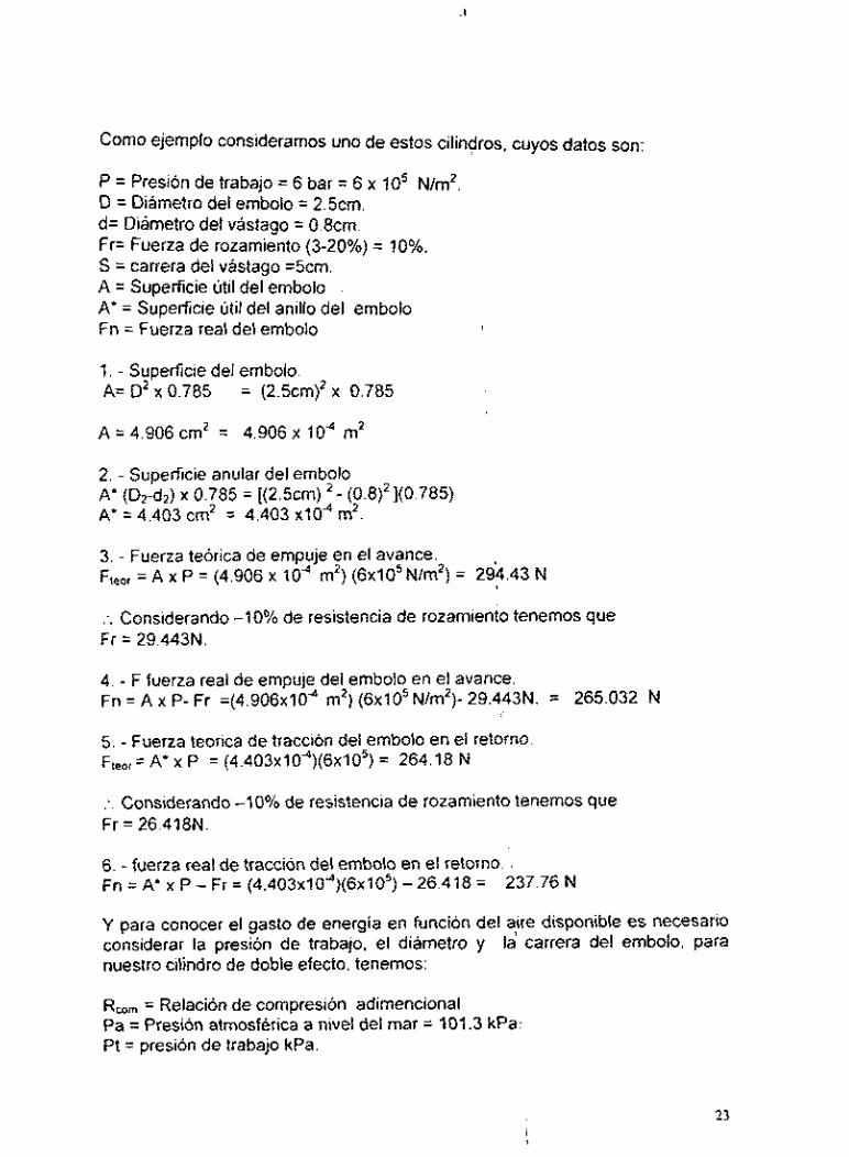
Como ejemplo considerarnos uno de estos cilindros, cuyos datos son:
P = Presión de trabajo = 6 bar = 6 x IO5 Nlm'. D = Diámetro del ernbolo = 2.5cm. d= Diámetro del vástago = 0.8crn. Fr= Fuerza de rozamiento (3-20%) = 10%. S = carrera del vástago =5cm. A = Superficie útil del embolo A' = Superficie útil del anillo del embolo Fn = Fuerza real del embolo
1. - Superficie del embolo. A= D2 x 0.785 = (2.5cn-1)~ x 0.785
A = 4.906 cm2 = 4.906 x l o d m2
2. - Superficie anular del embolo A" (D2-d2) x 0.785 = [(2.5cm) 2 - (0.8)2](0.785) A* = 4.403 cm2 = 4.403 x10⁴ m2.
3. - Fuerza teórica de empuje en el avance. F,,,, = A x P = (4.906 x lod m2) (6x10⁵N/m2) = 294.43 \ N
:. Considerando -10% de resistencia de rozamiento tenemos que Fr = 29.443N.
4. - F fuerza real de empuje del embolo en el avance. Fn = A x P- Fr =(4.9O6x1Od m2) ( 6 ~ 1 0 ~ N/m2)- 29.443N. = 265.032 N
5. - Fuerza teorica de tracción del embolo en el retorno F,,,,=A'x P = (4.4O3x10")(6x1O5) = 264.18 N
:. Considerando -10% de resistencia de rozamiento tenemos que Fr = 26.418N.
6. - fuerza real de tracción del embolo en el retorno. , Fn = A' x P - Fr = (4.4O3x1Od)(6x1O5) - 26.418 =
Y para conocer el gasto de energía en funcion del aire disponible es necesario considerar la presión de trabajo, el diámetro y la carrera del ernbolo, para nuestro cilindro de doble efecto, tenemos:
Rmm = Relación de compresión adirnencional Pa = Presión atmosférica a nivel del mar = 101.3 kPa1: Pt = presión de trabajo kPa.
237.76 N
23

Q = Consumo del aire en Urnin. S = Longitud de la carrera cm. N = Ciclos por minuto ( l/min) = 14
I. - Relación de compresión
Pa+Pt 101.3+600 Pa 101.3
- - 6.9 Rcomp = -
2. - Consumo de aire
Q = [s(0.785D')+s(0.78j(DL -d'))]nRcomp
Q = [5 x 0.785 x (2.q2 + 5 x 0.785 x ( (2.5)' - (0.8)' ) ] x 14 x 6.9
Q = (24.53 + 22)(96.6) = 4494.79 cm3/min. = 4.5 litros / min.
Una vez realizado esto para los 5 cilindros que tiene el FA, se decidió por el modelo AW2000-02 que es el modelo que cubre las necesidades del prototipo, según los datos del catalogo de SMC.
Calculos de la Banda Transportadora
Las dimensiones de este mecanismo se obtuvieron con la siguiente fórmula:
'I
' I
Donde:
L es la longitud total de la banda S la distancia entre centros r radio de la polea menor R radio de la polea mayor 6 es el ángulo que existe entre la polea mayor y la menoi
Sustituyendo los valores
S = 392mm e = O" R = r = 24mm
Se tiene:
24

L = 784 + 150.8
L = 934.8mm
Por lo que la longitud total de la banda será de ,935mm
Después de haber definido la longitud de la banda, se procedió a la búsqueda de la misma concluyendo en lo siguiente:
Tipo de banda: Transportadora y de proceso continuo (sin - fin) Fabricante : Chiorino Italia (Cia . Industrial Biella S. A. De C. V. ) Material poliuretano Modelo: 1 M6UO-U2 Código de fabricación: 1 M600055x940 Dimensiones: longitud 935mm. ancho 58mm, espesor =0.8rnrn
Las especificaciones técnicas se presentan en el apéndice B
La velocidad periférica de la banda se calculó con la siguiente fórmula:
Donde:
V: Velocidad periférica D. Diámetro de la polea N: rpm a las que gira el rodillo
Sustituyendo valores se tiene:
3.14.16.~2.4.~40 1 O0
I’ =z = 3.0lm/min
La cantidad de revoluciones que debe dar el rodillo para que la banda de una vuelta, se calculó de la siguiente manera:
donde:
2s

!I
Cr : es la cantidad de revoluciones del rodillo P : es el perímetro del rodillo
Sustituyendo valores se tiene:
1' = nD
V= 3.1416x2.4 = 7.53cm =0.0753m
0.935
0.0753 Cr = = 13.42rei~olucione
por lo tanto 12.42 revoluciones del rodillo = 1 revolución de la banda
Cálculo de las revoluciones que da la banda cuando el motor gira a 58 rprn
Si por cada 12.42 rev del rodillo se obtiene 1 rev de banda Para 58 rpm se tendrán
i
x rev de banda
Por io tanto:
(58rpni)( Irevhand)
I2.42revádroáillo .i = = 4.67rpm
2.3 Descripción de los procesos de fabricación de los elementos mecánicos
Los elementos que integran cada uno de los mecanismos se construyeron en los talleres convencionales del CNAD, así como en la electroerosionadora y el centro de maquinado ciya programación se hizo en equipos FANUC (Fanuc Automatic Progranhing Tool) que permite incrementar y optimizar la productividad de las máquinas de CN. Se utilizaron los diferentes equipos y maquinarias como son la dobladora, la cortadora. el taladro de banco la rectificadora de 'superficies planas etc. Para la fabricación de cada pieza se tomó en cuenta los siguientes aspectos teóricos: 'I
Una operación de Torneado consiste en el arranqie de viruta para elaborar piezas cilíndricas, tales como los rodillos, pernos y; separadores de la banda transportadora, acoplamientos de motores, cuerpo y broquero del taladro, así como bujes y acoplamientos para'el husillo.
Los parámetros más importantes que se consideriaron en esta operación, fueron: la velocidad de avance de la herramienta ( s ) medida en mmírev, el número de revoluciones ( n ) medida en rpm, la velocidad de corte ( Vc ) dada en m h i n y el tiempo de corte ( T ) en minutos. Para lo cual se utilizaron las siguientes fórmulas:
26

n =Vc / í r D
T = L / n s
De donde: N = número de revoluciones D = diámetro de la pieza Vc = velocidad de corte T = tiempo de maquinado L = longitud de la pieza s = avance de la herramienta
Una máquina cizalladora, consta de dos cuchillas, una fija y la otra movible, la cual generalmente tienen un ángulo con respecto a la cuchilla fija, con la finalidad de reducir el esfuerzo al corte dichas cizallas al moverse en sentido contrario, actúan sobre el material a cortar, tal es!:el caso de la lámina de acero que se corto y se dobló para formar los almacenes las tapas superiores del gabinete, las tapas laterales del husillo, las bases sujetadores para la estación de taladrado, el soporte de la unidad de mantenimiento, entre otras.
Para conocer la fuerza necesaria para cortar un material a través de este tipo de máquinas se utilizan las siguientes formulas 1
F = A o
A = % e L
L = e I tan ?.
Donde: F = fuerza necesaria para el corte A = área de la sección de corte e = espesor del material L = longitud del corte O = resistencia del material
Doblar consiste en modificar la forma de un objeto generalmente lámina o placa metálica, sometiendola a flexion hasta alcanzar su Ih i te elástico sin alterar su espesor, de modo que todas las secciones se conser$en iguales. Para el doblez hay dos conceptos básicos a considerar: el radio mínimo de doblez y el retroceso elástico por lo que el valor mínimo del doblez debe de ser cuando menos el valor del espesor del material y como maximo de 7 a 8 veces el espesor y de esta forma asegurar un buen doblez permanente.
Como ya se mencionó anteriormente, casi toda la lámina de acero que se corto con la cizalla, se dobló en una máquina dobladora, por lo que para asegurar el

buen desarrollo del material y conseguir las medidas deseadas, se recurrió a las siguientes fórmulas:
L = A + B + .... + n + nn I 2 ( r + h ) ..............._... <. para dobleces a 90"
Donde: L = longitud total del material a doblar A, B, C.... = longitud de los lados rectos conocidos n = número de lados conocidos r = radio deseado del doblez h = distancia del plano neutro ( por lb general a la mitad del
espesor del material )
L = 0157.3 ( r + h )
Donde: 0 = ángulo deseado del doblez
Sin lugar a duda una de las operaciones mas recurridas durante la elaboración del prototipo, fue el taladrado que consiste en efe$tuar un hueco cilíndrico en un cuerpo, mediante la herramienta denominada broca, además del taladrado, también se realizaron barrenados, que básicamente es agrandar un hoyo previamente hecho y el rimado. que sirve para dar precisión al mismo, estas operaciones se hicieron en casi todas las fijaciones, ya que los barrenos fueron machueleados para introducir tornillos, por otra parte también se barreno el panel frontal para colocar los interruptores, conectores e indicadores.
La mayoría de los barrenos fueron hechos con un taladro manual, pero algunos de ellos se realizaron en un taladro de banco y otros inclusive en la fresadora vertical con brocas helicoidales tanto milimétricas cbmo en sistema inglés.
Para efectuar el taladrado, se consideraron los siguientes parámetros: número de revoluciones, velocidad de corte, velocidad be avance y el momento torsional.
Vc= i[ D n I1000
S = 3 0 D I100
Mt = o D' s I 8
Donde: n = número de revoluciones D = diámetro de la pieza Vc = velocidad de corte S = avance de la herramienta Mt = momento torsional U = resistencia al corte del material
28

Es importante hacer notar que no todas 1as;piezas fueron fabricadas en los talleres del CNAD sino que fueron adquiridas en el mercado después de un cuidadoso análisis para asegurar su funcionamiento, por ejemplo para el$ caso del tornillo embalado, una vez que se determinó el diámetro se procedió a la fabricación del mismo, pero cuando nos dimos cuenta que en el taller no se tenian las herramientas para la construcción del tornillo y tuerca se procedió a hacer una evaluación económica del tornillo que se quería fabricar con tornillos que existen en el mercado y al observar que los costos son muy aproximados se decidió comprar un tornillo con su tuerca que comercialmente se encuentran en el mercado, cabe hacer mención que existian tornillos más caros pero considerando economia y utilidad nos inclinamos por un tornillo de cojinete con rodamientos ya que el costo de fabricación y de compra variaron muy poco con las ventajas de eficiencia, simplicidad, respuesta 'adecuada en la transmisión de movimiento precisión, confiabilidad y operación silenciosa.
La rosca de tornillo embalado o tornillos de cabeza redonda se puede considerar como la carrera de un balin endurecido. La tuerca consiste de una serie de balines que circulan a través de una carrera similar, los balines son transferidos de un extremo de la tuerca al otro por;medio de un tubo guia. Estos tornillos eliminan la fricción de deslizamiento que existe en los tornillos de potencia convencionales. Todas las fuerzas de (eacción entre el tornillo y la tuerca son soportadas por los rodamientos y dependiendo de la necesidad en cuanto a una determinada cantidad de cargd y del constante esfuerzo operacional a que va a estar sometido el mecanisio se debe hacer la selección de las dimensiones del tornillo y la tuerca y de la cantidad de circuitos de bolas necesarios para optimizar el funcionamiento.
El 90 YO de eficiencia mecánica comparado con el:,30% de un tornillo de rosca trapezoidal o ACME hicieron que nos decidiéramos por la compra del tornillo y la tuerca embalada, además de que la vida útil es mucho mayor y al eliminar la fricción entre el arranque y paro del movimiento elidinan la vibración cuando se requiere un movimiento lineal y suave.
Otro caso fueron los Cilindros neumáticos, las váldulas electroneumáticas, los sensores, la tornilleria etc.
!I
3 DESCRIPCI~N DEL SISTEMA DE CONTROL
3.1 Diagrama de bloques y descripción del sistema de control
El siguiente diagrama de bloques muestra la forma en que actúa el sistema de control, donde se observa que cualquier señal proveniente de una PC. un PLC, sensores o de un interruptor manual, deberá acondicionarse para que se pueda enviar a los actuadores, correctamente y no se ocasionen danos al FA.
29

L
, [FTify Acondiciona-
miento de señal Protección
(Detiene el proceso en
caso de
errores) potencia E S . u I '
: I I interruutore! ' I ! . .
I I I
E . Manuales
. . . ........... " .............. Retroalimentación
Un wleclor perniite cambiar de PC 3 P1.C o a modo Manual
Este sistema cuenta con tres modos de operación los cuales son: PC, PLC y manual. El selector del modo de operación se encuentra en el tablero de control y al elegir la opción requerida, este manda una sena1 de activación a las tarjetas, por ejemplo:
Si se selecciona el modo de operación PC, al estar el FA en movimiento, los actuadores activan sensores los cuales leen la computadora y toma la decisión correspondiente segun su programa, enviando a su vez un comando que pasa por un circuito de protección el cual revisa que la información no sea errónea

para activar a los actuadores, repitiéndose el ciclo, si la información mandada es errónea el circuito de protección detiene todo el sistema y activa una lampara indicadora de error.
La misma situación de protección ocurre cuando se elige el tipo de operación por PLC.
Para el modo manual, al activar un interruptor la señal pasa por el circuito de protección y de allí al actuador correspondiente. La retroalimentación en este caso se realiza visualmente por el operario y si este comete un error el circuito de protección detiene el sistema, evitando con esto danos físicos al equipo.
Para la operación de todos los elementos del FA se cuenta con una fuente de poder que proporciona los voltajes y potencias adecuados.
En la computadora debe de instalarse un puerto múltiple de entradas y salidas para comunicarse con el sistema de control del FA. Este puerto es parte del sistema de control del FA.
El sistema de control consta de:
I. Una tarjeta principal 2. Una tarjeta que suministra 5V, 12 V y 24 V; además cuenta con el control
3. Una tarjeta de entrada para la computadora (PC IN) 4. Una tarjeta de salida para la computadora (PC OUT)
manual de los actuadores (Tarjeta de Fuente)
5. Una tarjeta de entrada para PLC'(PLC IN)'y tarjeta.de protección (Tarjeta de Gals)
6. Una iarjeta de salidas para PLC (PLC OUT) y tarjeta para manejar la etapa
Tarjeta principal
La tarjeta principal transporta la información en paralelo (bus de información) de los sensores y los actuadores hacia las tarjetas de entradas y salidas de la computadora y el PLC respectivamente, asi mismo suministra energía a cada una de las tarjetas.
La información que se envía o se captura para la PC o PLC se transmite a traves de bornes de conexión (ciernas) y cuando la operación se hace manualmente solo se envia información hacia los mecanismos.
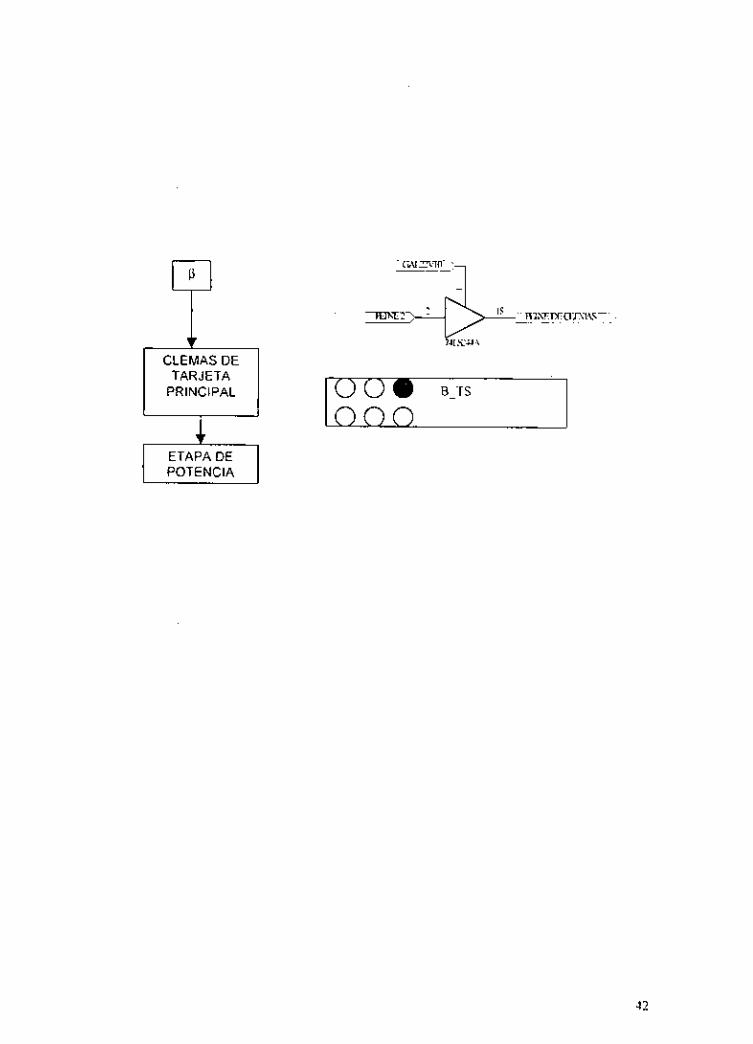
Tarjeta de fuente
Esta tarjeta suministra el voltaje y cuenta con tres fuentes de poder independientes entre si y son de 5V, 12V y 24V, los cuales se utilizan para
de potencia (Tarjeta de Potencia).
31

operar los diferentes sensores y actuadores de los mecanismos que integran el FA.
En esta tarjeta también se encuentra la operación manual del FA, la setial se obtiene de los interruptores del panel frontal que entran a la tarjeta, a través de un header de 12 pines, esta señal se invierte con un circuito integrado 74LS240, y después se suministra al bus de la tarjeta principal hasta la tarjeta de protección, donde la señal se supervisa y valida por las Gals, para enviarse a las clemas e introducirse a la etapa de potencia y efectuar el movimiento requerido por los interruptores del panel frontal.
32

La siguiente figura muestra en un diagrama de bloques, el camino que presenta la setial, el circuito electrónico, el header y los bornes de conexión de la tarjeta fuente.
HEADER QUE CONECTA LOS
INTERRUPTORES DEL PANEL A LA
TARJETA FUENTE
ACTlVACl6N MANUAL

-7 T TARJETA
PRINCIPAL
+I POTENCIA
B-TS 1
Tarjeta de PC IN
Esta tarjeta permite la entrada de las señales eléctricas a la PC, recibe y procesa los estados de los sensores a través de un conector localizado en la tarjeta principal y con base al programa que se este efectuado toma decisiones para activar (a través de la tarjeta de salidas de la PC) los actuadores de los mecanismos determinados.
Las tarjetas de entrada y salida del PLC también operan igual, la diferencia es que las señales de comunicación con el PLC se efectúan a través de Headers.
Para evitar la caída de las señales, se utilizan los Buffer 74LS240 ylo 74LS244 y resistencias de Pull Up de 10 KR. también se usaron optoaisladores para aislar etapas en las que se pudiese generar un corto y daiiar el PLC o la PC.
A continuación se muestran los diferentes caminos que siguen las señales de entrada y salida en los diferentes tipos de operación (PLC y PC). El diagrama de bloques, el circuito electrónico y los slots 1 y 2 de la tarjeta de protección.
34

ENTRADAS DE SENALES ELÉCTRICAS DE LOS SENSORES A LA COMPUTADORA
SENSOR iri TARJETA
PRINCIPAL
TARJETA PRINCIPAL
35

I ENTRADASDE 1 I pc I
PEINE 1 P CONECTOR
TARJETA PRINCIPAL i HACIA LA PC
K N i
36

Tarjeta de PC OUT
La siguiente figura muestra la salida de las señales de la computadora a los actuadores, el circuito electrónico, los slots 1 y 2 de conexión a la tarjeta de protección y los bornes de conexión a la etapa de potencia.
DE LA PC A LA TARJETA PRINCIPAL
U
37

IPI T 1
CLEMAS DE TARJETA
PRINCIPAL
74LsUA
POTENCIA
38

PLC IN y tarjeta de protección (Tarjeta Gals)
La siguiente figura muestra la entrada de las señales eléctricas de los sensores al PLC, circuito electrónico, bornes de conexión, slots 1 y 2, tarjeta de protección y circuito electrónico de las tarjetas de entrada al PLC.
CLEMAS DE TARJETA
PRINCIPAL
PROTECC16N
PEINE 2 DE LA TARJETA
PRINCIPAL
I\' T
39
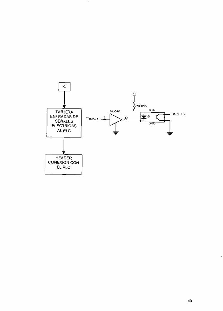
TARJETA ENTRADAS DE - . .m~IEz.,
SENALES ELECTRICAS
__
AL PLC Y HEADER
CONEXi6N CON EL PLC
40
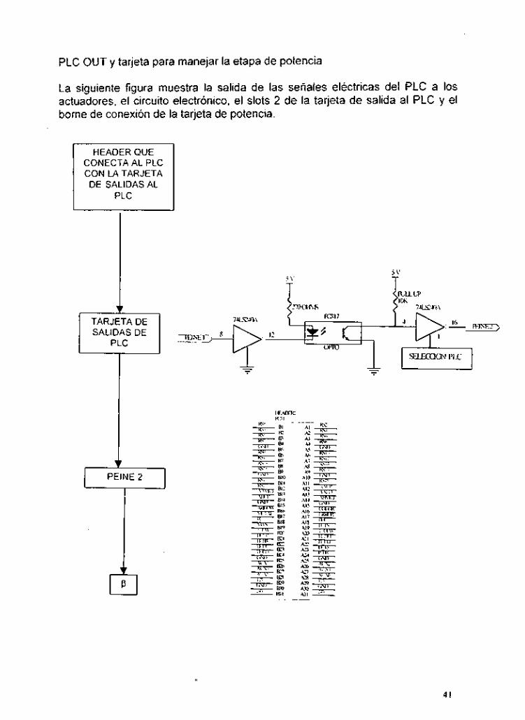
PLC OUT y tarjeta para manejar la etapa de potencia
La siguiente figura muestra la salida de las señales eléctricas del PLC a los actuadores, el circuito electrónico, el slots 2 de la tarjeta de salida al PLC y el borne de conexión de la tarjeta de potencia.
I
HEADER QUE CONECTA AL PLC CON LA TARJETA DE SALIDAS AL
I
PEINE 2 II
I I I \
I
41
TARJETA PRINCIPAL
POTENCIA
iooe B-TS
42

Selector de mando de operación
El circuito electrónico que permi FA es el siguiente:
Las señales eléctricas provenientes de los sensores entran a las tarjetas de PLC y PC. Las señales de a los actuadores se seleccionan con la tarjeta que va a controlar esta selección se realiza activando los buffers en las terminales 1 y 19 del circuito un selector que esta
tal manera que se le
e seleccionar el modo de operación del
43
3.2 Descripción de los elementos del sistema
3.2.1 Elementos de entrada
La siguiente tabla describe las entradas correspondientes a los sensores del FA.
44

ENTRADAS (SENSORES)
RS1
DESCRIPCI~N
Interruptor de limite de la mesa giratoria en sentido antihorario
I sobrecarrera. I Interruptor de limite en la parte alta de la torre del brazo en RS8
RS2 RS3 RS4 RS5 RS6 RS7
en sobrecarrera Interruptor de limite de la mesa giratoria en sentido antihorario Interruptor de limite de la mesa giratoria frente al almacén A Interruptor de limite de la mesa giratoria frente al taladro Interruptor de limite de la mesa giratoria frente al almacén B Interruptor de limite de la mesa giratoria en sentido horario Interruptor de limite de la mesa giratoria en sentido horario en
-
- sobrecarrera RS9 RSIO RSI 1 RS12
Interruptor de limite en la parte alta de la torre del brazo Interruptor de limite en la parte media de la torre del brazo Interruptor de limite en la parte baja de la torre del brazo Interruptor de limite en la parte baja de la torre del brazo en
I almacén A 1 Sensor fotoeléctrico aue detecta Dieza en la parte media del AAMID
RS13 RS14 RS15 RS16 RS17 RS18 RS19 AAUP
sobrecarrera Sensor Reed en posición frontal de la garra Sensor Reed en posición retraída de la garra Sensor Reed en posición frontal del taladro Sensor Reed en posición retraida del taladro Sensor Reed en posición frontal del pateador Sensor Reed en posición retraida del pateador Sensor bigote de gato en fin de banda Sensor fotoelectrico que detecta pieza en la parte alta del
ABUP
ABMlD
ABLOW
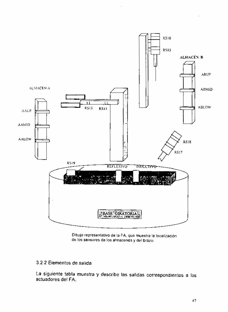
El siguiente dibujo muestra la ubicación de los distintos sensores que tiene el sistema FA.
almacén A Sensor fotoeléctrico que detecta pieza en la parte alta del almacén B Sensor fotoeléctrico que detecta pieza en la parte media del almacén B Sensor fotoeléctrico que detecta pieza en la parte baja del almacén 13
45

ALMACÉN
AAUP
A’\ M I I)
A.4LOW
A
RS3 RS4
ALMACÉN B
ABUP
ABMID
4n~on
46
AL1ACF.N A
AAUP
AAh,llí>
AALOW
RS16
RSlj
ALhlACÉN B
ABUP
ABMID
ABLOW
Dibujo representativo de la FA, que muestra la localización de los sensores de los almacenes y del brazo.
3.2.2 Elementos de salida
La siguiente tabla muestra y describe las salidas correspondientes a los actuadores del FA.
47

(ACTUADORES) H-CO
OPTS
Activación de la garra neumática 1 = Cierra O= Abre
Activación del motor del taladro -
P-FE3
BJS
D-CO
O= Posición atrás D-DU I Activación del cilindro del taladro (cilindro de doble efecto)
1 = Arranque O= Paro
Activación del alimentador de piezas (cilindro de doble efecto) 1 = Posición al frente O= Posición atrás
1 = Arranque O= Paro
Activación del sujetador de la pieza a taladrar (cilindro de simple efecto)
Activación del motor de la banda transportadora
1= Posición al frente
H-FB
H-DOWN
H-UP
T-CCW
T-C W
3.2.3 Controlador
Se utilizan básicamente dos tipos de controladores que son: a) PC b) PLC
1 = Posición abajo O= Posición arriba
1 = Posición al frente O= Posición atrás
Activación del motor de la torre central hacia abajo 1 = Arranque O= Paro
Activación del motor de la torre central hacia arriba I = Arranque O= Paro
1= Arranque O= Paro
Activación del brazo (cilindro de doble efecto)
Activación del motor de la mesa giratoria en sentido antihorario
Activación del motor de la mesa giratoria en sentido horario

A I O O 1 1
Configuracion de datos
(Registro de la palabra de control)
Las direcciones que se utilizaron para la programación de esta interface, son: 300H, 301H, 302H, 303H, que corresponden a PA, PB, PC y la palabra de control respectivamente para el primer PPI. Para el segundo PPI le corres@pnden las direcciones 304, 305, 306, 307 que también corresponden a'ei PA, PB, PC y palabra de control respectivamente. Ya que el FA cuenta con 24 entradas y 11 salidas, se utilizaron los tres puertos del primer PPI configurados como puertos de entrada, y los tres
A0 FUNCION O PUERTO A 1 PUERTO B O PUERTO C 1 PALABRA DE CONTROL
49

D7 D6 D5 04 D3 D2 D I 1 O O PA PCH O PB 1 O O 1 1 o 1 1 O O O O 0 0
NOTA: CW = Control Word = Palabra de control
DO PALABRADECONTROL PCL
1 96 H (PPI 1) O 80 H (PPI 2 )
50

IMODULO
1
PLC PANEL I PIN DEL DESCRIPCION
IN0 s2 9,lO Mesa giratoria en sentido CONTROL CON2X25
IN1 s 3 7 3 I Mesa giratoria frente ai
NOTA: IN = Entrada al PLC
IN2 IN3
IN4
51
aimacén A s 4 5,6 Mesa giratoria frente al taladro s5 3,4 Mesa giratoria frente al
almacén B S6 17,18 Mesa giratoria en sentido

Salidas del PLC /entradas al FA
La tabla que sigue presenta la disposición de las salidas en el panel de control para la utilización del PLC:
OUT0
OUT1
1 MODULO 1 PLC \PANEL/ lPlN DEL I DESCRIPCION CONTROL CON2X25
P I 1,2 Mesa de trabajo l sentido
P2 3.4 Mesa de trabajo / sentido horario
, . - OUT2 P3 5,6 OUT3 P4 7 3 Braz OUT4 P5 9,lO Garr OUT5 P6 11,12 Garr OUT6 P7 13,14 Talaaro SI
OUT7 P8 25,16 Taladro arranque I paro OUT8 P9 17,18 Sujetador de piezas a taladrar
- 1
vcc GND
ube / baia
I I I
ai frente I atrás OUT9 P10 19,20 Pateador al frente / atrás OUT10 P I 1 21,22 Banda arranque I paro
PLC 24V SC TIERRA
NOTA: OUT = Salida del PLC
La operación en modo PLC usa los conectores banana hembralmacho localizados en el panel de control denominados P I a P11, S1 a S24, así como el denominado PLC y CC.
Para este modo de operación debe de seguir los siguientes pasos: I. Seleccione el modo PLC 2. Conecte el PLC con el panel de control del FA. 3. Energice al PLC. 4. Energice el FA. 5. Ejecute el programa de control.
Configuración de las señales de la tarjeta de salidas de PC (OUT)
52

Peo ( PPI 2 ) Pel ( PPI 2 )
pez ( PPI 2 )
Top 2 D-CO Bottom 24 Bottom 1 P-FB Top 24
Top 1 B-TS Top 19

Configuración de las señales de la tarjeta de salida por control MANUAL (OUT)
Pin 4 D-CO Bottom 24 Pin 3 P-FB Top 24 Pin 2 B-TS Top 19
- Pin 1 GND
esta tarjeta se
peine 2 terminal
3.3 Esquemas y tarjetas de circuito impreso (PCB)
Las siguientes figuras muestran cada una de las tarjetas y los circuitos impresos del FA.

Vista posterior del PCB de la TARJETA DE SALIDAS DE LA PC / ENTRADAS A FA (PPI)
55

Circuito esquemático d e la TARJETA DE SALIDAS DE LA PC (PPI) / ENTRADAS A FA
56

Vista superior del PCB d e SALIDAS DE FA I ENTRADAS A LA PC
la TARJETA DE
57

Fig. DE SALIDAS DE FA I ENTRADAS A LA PC
Vista posterior del PCB de la TARJETA
58

Diagrama esquemático de la TARJETA DE SALIDAS DE FA I ENTRADAS A LA PC
59

Vista superior del PCB de SALIDAS DE FA I ENTRADAS AL PLC
la TARJETA DE
60

8 0
O
0
O
O
o
O
O
O
O
D
O
o
0
P
o
O
O
Q O
Vista posterior del PCB de la TARJETA DE SALIDAS DE FA I ENTRADAS AL PLC
61

i-
<:.,., ................ . . . . . . . . . . . . . . . . . . . . . . . . ,,
................................

n o O 0 o w
' D O b b v o bú
Vista superior del PCB de la TARJETA DE SALIDAS DEL PLC I ENTRADAS A FA
63

O o P- o
Vista posterior del PCB de la TARJETA DE SALIDAS DEL PLC I ENTRADAS A FA
64

I I

Vista superior del PCB de la TARJETA DE PROTECCIdN DE FA
66

Vista posterior del PCB de la TARJETA DE PROTECCIÓN DE FA
67

W W

-I"-
Vista superior del PCB de la TARJETA DE FUENTE DE ALIMENTACIÓN Y CONTROL MANUAL DE FA
69

Vista posterior del PCB de la TARJETA DE FUENTE DE ALIMENTACIÓN Y CONTROL MANUAL DE FA
70


o o o o o o o o o o o o o o o o o a o o o o o o m o 0 0 0 0 0 0 0 0 0 0 0 0 0 0 0 0 0 0 0 0 0 0 0 0 0 o
Parte superior de la tarjeta principal de FA
72

Pane posierior de la tarjeta principal de FA
73

l R S l 2 0 0 IRSI
IRSI3 0 0 lRS2
IRS14 0 0 lRS5 O O O N
IRSI5 0 0 IRS4 i.' o IRS16 0 0 lRS5
IRS17 0 0 lRS6
IRSI8 0 0 IRS7
lSR19 0 0 IRS8
AAUP 0 0 IRS9
AAMlD 0 0 IRSlO
AALOW 0 0 I R S l l
ABUP 0 0 ABMID
ABLOW 0 0 COLOR
PC o o pLc
MAN o 0 T- CCW 0 0 H-UP
H-DOWN 0 0 H-FB v) v1 w w e
H-CO 0 0 D-TS 8C 2 3
P-FB 0 0 B-TS vi6 D-CO 0 0 D-DU <
2 2 T-C W 0 0 OERR 6-2
5 5
<
.xu
Distribución de clemas de la tarjeta principal del modulo de Fabrica Automatizada
74

- B17 - BIS - B19 - m - B21 - E M
-IFl,c -/ Ai6 Ai7 m Al8 - \ A19 - A20 '- A21 - A22-
A26- \ An-
A.3
A31
A28 -or-Du m u u L u
\ .- CON AT63
/
Identificación de las terminales del slot de clemas de la tarjeta principal de FA.
75

h
n U
n "
- 'Z - - U J .A o e U c O
- o.
N 5 U
U -J n U .- c

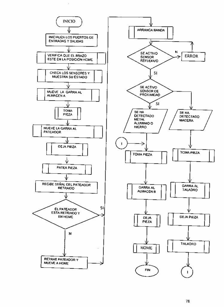
INICIO ii 1
INICIALIZA LOS PUERTOS DE ENTRADAS Y SALIDAS
ESTE EN iA POSICi6N HOME
MUESTRA SU ESTADO
ALMACENA
PATEADOR
ESTA RETRAIDO Y
N
MUEVE A HOME
ARRANCA BANDA m SE ACTIVO SENSOR REFLEXIVO
J/
DETECTADO DETECTADO
ALUMINIO O HIERRO
ALMACEN E!
2 I
DEJA PIEZA 9 TALADRO 7?
78

RECIBE S E M L DE LA POSICION DE LA GARRA 1
GARRA AL
RECIBE S E U L DE NIVELES DE ALMACENES
FRENTE RETRAE GARRA
ESTA FRENTE AL NIVEL DONDE
SE MUEVE AL
ESTA LA PIEZA
GlRAA POSIC16N HOME
1 RETURN RECIBE S E h L DE LA POSICION DE LA GARRA
79

[ J
V
GARRA. GARRA CERRADA POSISICON HOME Y POSlSl6N EN QUE SE ENCUENTRA
J ESPERA 2 SEGUNDOS
SE MUEVE A LA POSICION
80

1 I GARRA AL ALMCLN B
RETRAIDA, GARRA CERRADA. POSIC16N HOME
ALMACEN B I I
l
ARRANCA BANDA
GARRA RETRAIDA. GARRA CERRADA Y ACTIVAC16N DE PATEADOR
MUEVE A HOME
PASTEADOR
SEGUNWS
(5 RETURN
BANDA
FIN DE .;71 BANDA
I S
DETIENE MOTOR 9 6 RETURN
81
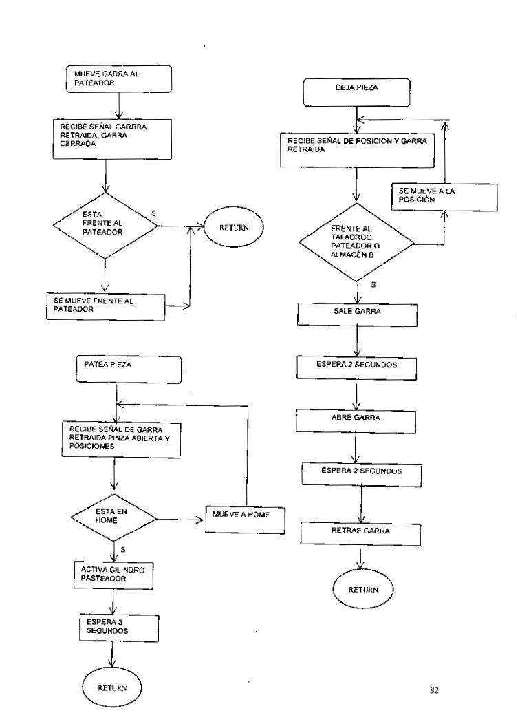
I MUEVE GARRA AL PATEADOR
RETRAIDA, GARRA CERRADA
PATEADOR
I l+----l
RETRAIDA PINZA ABIERTA Y
DEJA PIEZA u
MUEVE A HOME
PASTEADOR
+ . RECIBE SENAL DE POSlClbN Y GARRA RETRA~DA
SE MUEVE A L4
SEGUNDOS
* SALE GARRA * ESPERA 2 SEGUNDOS
I
82

CHECA SENSORES
!IILz! RECIBE SENAL DEL LS UBICADO FRENTE AL ALMACCN A I
TODAS LAS SENALES +:,- DEL DESACTIVADAS LS UBICADA MENOS FRENTE LA AL MESA EN POSICION
I TODAS LAS SENALES
GFRENTE AL DESACTIVADAS MENOS LA FRENTE AL ALMACCN DELLS UBICADA FRENTE AL
MESA EN POSICION
/
SOLO SE ACTIVA LA SENAL DEL LS OUE ESTA FRENTE AL TALADRO
DEL PATEADOR

SE ACTIVAN OTRAS CEÑALES Y ENTONCES HAY ERROR
<
BRAZO EN SE ACTIVA EL L S QUE SE POSICION ENCUENTRA EN iA PARTE
ALTA DEL BRAZO
BRAZO EN POSIC16N BAJA
<-*I BRAZO EN POCiC16N
SE ACTIVA EL L S QUE SE ENCUENTRA EN LA PARTE MEDIA DEL BRAZO
MEDIA
SE ACTIVA EL L S QUE SE ENCUENTRA EN iA PARTE BAJA DEL BRAZO
PARTE RETRAIDA DEL
GARRA AL FRENTE
ERROR CORRIGE
84

SOLO SE ACTIVA LA S E U L RETRAIDA DEL SENSOR UBICADO EN
LA PARTE POSTERIOR DEL
GARRA RETRAIDA
85

> NIVEL ARRIBA
S SOLO SE ACTIVA LA SEIÚAL DEL SENSOR UBICADO EN
NIVEL MEDIO EL NIVEL MEDIO ’
SOLO SE ACTIVA LA SEIÚAL DEL SENSOR UBICADO EN EL NIVEL DE ARRIBA
< PIEZA EN ALMACEN A NIVEL MEDIO
PIEZA EN EL ALMACEN A NIVEL BAJO
SOLO SE ACTIVA LA SEIÚAL DEL SENSOR UBICADO EN EL NIVEL BAJO
<
S
NO HAY PIEZAS
86

I A
V < PIEZA EN ALMACEN B
NIVEL MEDIO
PIEZA ENALMACEN B ARRIBA 1
/ - SOLO SE ACTIVA LA SEt3AL DEL SENSOR UBICADO EN EL NIVEL BAJO
S ’ I
L
4.1.2 Programa de control del sistema
A partir de la siguiente página se muestra el programa de control del FA, que se utilizó para probarlo, es importante destacar que antes de que haga alguna práctica se tenga la seguridad del funcionamiento del equipo, por lo que en este programa se incluyen subrutinas de diagnóstico para las diferentes partes que conforman este sistema rnecatrónico.
88

Option Explicit D i m a h.c.d.e. tp. h . i . j . t I . m . n . a . p . q . r . s . L u . V . X . Y . 7 . Dim LedON. LedOFF. LcdVerde. SENSOR!. SENS0RZ:SI. S2 Dim PZA As String 'Declare use ofthe DLL Private kc la re Function Out8255 Lib "8255.dll" (ByVal PonAddress As Integer. ByVal PonData .A5 In tqcr ) . A S Inic$ir Private Declare Function In8255 Lib '8255.dll" (ByVal Pon4ddrers As Integer) A s Intcgcr 'Declare wiables Dim Dummy As Integer: 'Dummy variable used with DLL Dim PA1 As Intcgcer: '8255 Pon A address Dim PBI As Integer: '8255 Pon B address Dim PCI As Integer: '8255 Pon C address Dim CWI As Integer: '8255 Control Address Dim P42 As Integer: ' 8255 Pon A addrers Dim PB2 As Integer: '8255 Port B address Dim PC2 As Integer: '8255 Pon C address Dim C\\2 As Intcgcr: '8252 Conml Address 'ENTRADAS Dim hlesaliome. MesaFteTaladro. MesaFteAA. MesaFteAB. MesaFtePateador. BruoAlio. Brauhlcdio. BrazoLhjo Dim GarraFte. GmaAtrar. TaladroAniba TaladroAbajo. PaieaFre. PateaAtras. PzaUandv Enoi Dim PzaAAI. PzaAA?. haAA3. PraABI. Pra4BZ. PzaAB3. Metal. Color 'SALIDAS Dim SujeiaTaladro. Pateador. Banda. McsaCU:. hicsaCCW. BraroSubs. BraroBa;a. G a n n F l Dim Garra. Taladro. TaladroONOFF. OFF Private Sub Dela!()
Dim Stan Dim Chcck Stan = Timer Do Until Check >=Stan + I
LOOP Check = Timer
End Suh Sub HOME0
'*'I REGRESA A HOME '** '"* REGRESA LA GARRA*** x = l"8255(PCI) X = X And GmaFtc I f X = GmaFtr Then
Dummy = Out8255(PA2. GanaFA) PBFrentcFillColor = LtdON PBAw.FillColor = LedOFF
PBFrentc.FillColor = LcdOFF PBAm.FillColor = LedON
End I f
"*' REGRESA APOSlClON CCW * * * >;=O a'hilc X <> hlcsaHomc X = ln8255(PBI) X = X And MesaHomc Dummy = Out825S(PA2. McsaCCW) PMCCW.FillColor = LedON PMCU'.FillColor = LedOFF
Wend Dummy = Out8255(PA2. OFF) PMCCW.FillColor = LedOFF PMCW.FillColor = LcdOFF MCW.FillCo1or = LcdON
'*** SUBE GARRA A POSICION ALTA * * * Y = O Whilc Y C> BmoAlto Y - ln825S(PBI) Y = Y And BrazoAlio Dummy = Ou18255(PA2. BraroSuk) PBArriba.FillColor = LedON PBAhajo.FillColor = LedOFF
Wend Dummy Oui8255(PA2. OFF) Dummy = Out8255(PBZ. OFF) PBAnibaFillColor = LedOFF
89

PBAbajo.FillColo! LcdOFF LedArriba.FillColor = LedON
End Sub
Sub SENSORESO I**. CHECA TODOS LOS SENSORES Y MUESTRA SU ESTADO **' '*** CHECA POSIONES DE LA MESA *** CIS
DoEvents
m = i And h1eraHome I f m = hIcraHome Then
SENSA:
s = I ~ E Z S S ( P H I )
hfEI.FillCalor = LedOFF hlCW.FillColor = LedOFF h l A FillColor = LcdOFF MT FillCalor = LedOFF hl.AB.FillColor = LedOFF h1CCW.FillColor = LedON hfE:.FillColor = LedOFF M r g Caption = 'MESA EN POSICION C C W
m =I And hleraFieAA I f m = hlcraFirAA Then
El%
hll~l.Fi l lColor- LedOFF hlCW.FillColar = LcdOFF hl~\:\.FillColor = LcdON hIT.FillColor = LedOFF MAH.FillColor = LcdOFF hiCCW.FillColar = LedOFF hlEZ.FillColor = LedOFF hlrp Caption = "MESA FRENTE AL ALMACEN (A)'
m = I And hlrraFieTaladro I f m = hlcsaFieTaladm Then
hl l i l SillColor = LrdOFF hlCW.FillColor = LedOFF hlAA.FillColor = LcdOFF hKFillColor = LcdON hlAH.FillColor = LedOFF h4CCW.FillColor = LcdOFF hlEZ.FillCalor = LcdOFF Msg.Caption = "MESA FRENTE AL TALADRO
m = I And MeraFteAB If m = MeraFieAR Then
Elst
El%
hfEI.FillColur = LedOFF hIC~U.FillCalor = LcdOFF MAA.FillColor = LcdOFF MT.FillColut = LcdOFF h4AB.FillColor = LcdON MCCW.FillColor = LedOFF MEZ.FillColor = LrdOFF MwCapt ion = "MESA FRENTE AL ALMACEN (E)"
m = I And McraFtrPatcador I f m = hícraFtcPa<cador Then MEI.FillColor = LcdOFF hlCW.FillColor = LedOFF MAAFillColor = LedOFF MT.FillCalor = LedOFF MAH.FillColor = LcdOfF MCCW.FillColor = LcdON MELFillColor = LcdOFF Msg.Caption = "MESA FRENTE AL PATEADOR"
híEI.FillColor = LcdON MCW.FillCalor = LcdOFF MAAFillColor = LcdOFF MT.FillColor = LcdOFF
Else
Elw
90

MAB.FillColor = LcdOFF MCCW.FillColor = LedOFF ME2,FillCoIor= LcdON Msg.Caption = "POSICION DE ERROR - CORRIGE EL ERROR PARA CONTINUAR" GaTo SENSA
End If End If
End I f End If
End If
'*- CHECA POSIONES DEL BRAZO -*
h = s And BmoAlto I f h = Brazo.4110 'Illhen
I = i m s ( P n i )
LedEI .FillCalor = LcdOFF LcdAniba.FillColor = LrdON I.edhlrdio.FillColor = LedOFF I.ed:ibajo.FillColor = LedOFF LcdEZ.FillColor = LedOFF Msg.Caption "BRAZO EN POSICION ALTA
h = s And Bmohledio I f b = Dramhledio Then
Else
I.rdEl.FillColor = LedOFF I.cd:\n~ba.FillColor = LedOFF Lcdhledio.FillCaloi = LedON ~
I.cdhbajo.FillColar = LcdOFF I.rdf?.FillColor = ILedOFF Msg.Caption = "BRAZO EN POSICION MEDIA
Elrc h = I And BrazoBajo If b = BrazoBajo Thcn
LcdliI.FillColor= LcdOFF LedAniba FillColor = LcdOFF Lcdh1edia.FillColor = LcdOFF LedAbajo.FillColor = LcdON LcdE2.FillColor = LedOFF Msg.Caption = "BRAZO EN POSICION BAJA
Else ILedEl .FillColor = LedON Led:\rriba.FillColor = LcdOFF Lcdhlcdio.FillColor = LedOFF LcdAbajo.FillColor = LcdOFF LcdEZ.FillColor = LcdON
GOTO SENSA Msg.Caplion = "POSICION DE ERROR -CORRIGE EL ERROR PARA CONTINUAR'
End I f I " d I f
End I f
' *** CHECA POSIONES DE LA GARRA * * o
a = 1"82'?(PCI] p = a 4nd GarraFic I f g = GarraFtc Then
PBFrcnte~FillColar = LcdON PBAuas.FillColor = LcdOFF Msg.Caption = "GARRA AL FRENTE .-+ ERROR"' CORRIGE EL ERROR PARA CONTINUAR
GnTo SENSA
e = a And Uarra4var Elw
l i p = ~ m d u a s ncn PBFrcntr.FillColor = LcdOFF PBAim.FillColor = LcdON Mrg.Capiian = "GARRA ATRAS"
Msg.Caplion = "GARRA EN POSICION DE ERROR - CORRIGE EL ERROR PARA CONTINUAR Elw
&To SENSA End If
End If
91

'*" CHECA TALADRO 'O'
a = ln82jj(PCI) g = a And TaladroAniba If g = TaladmAniba Then
PTAbaja.FillColor = LcdOFF PTAniba.FillColor = LedON Mrg.Capiion = 'TALADRO ARRIBA
F'TAbajo FillColor = LcdON PTAniba FillColor = LedOFF Msg.Capiion = 'TALADRO ABAJO ... ERROR*-' CORRIGE EL ERROR PARA CONTINUAR GoTo SENSA
Else
End I f
I**' CIIECA ALlhlENTADOR * * * a = In8?5i(PCI) d = a And PaieaFic l i d = PateaFie iñen
PPFrcnie FillColor = LcdON PP.4iras FillColor = LedOFF MSg~CaDlion = "ALIMENTADOR AL FRENTE -* ERROR"' CORRIGE EL ERROR PARA CONTINUAR GoTo SENSA
d = a And PaieaAtras I f d = P~ieaAirs Then
Else
PPFrrnir.FillColor = LedOFF PPAim FillColor = LedON hlsg Capiion = "ALIMENTADOR ATRAS'
Msg.CWon ="ALIMENTADOR EN POSICION DE ERROR CORRIGE EL ERROR PAW\ CONTINUAR COTO SENSA
t l lSC
End If End I f
'"* CHECA PIEZA AL FINAL DE L A BANDA '** f = a And PzaBanda I f f = RaBanda Then
Mrg.Capiion = 'PIEZA AL FINAL DE LA BANDA *** ERROR'.. CORRIGE EL ERROR PARA
Go10 SENSA CONTINUAR
End I f
I*** CHECA POSICION DE ERROR * * * c = a And Enor Ife = Emor Thcn
Go'ro SENSA hlrg.Capiion = "POSICION DE ERROR CORRIGELO PAR\ CONTINUAR"
End If
~ " * CHECA POSlONES DE LOS ALMACENES O * *
"*' CHECA ALMACENA *** z = In825S(PAl) Y = z And PraAAl If Y = PraAAl Thcn
LcdAl .FillColor = LedON LcdALFillColor - LcdOFF LcdAi FillColor = LedOFF hlrg.Caption = 'PIEZA ALMACEN (A) ARRIBA' PZA = I
v = L And PzaI\Ai If v = h a 4 2 ThThc"
Elw
LcdAI.FillColor = LedOFF LcdA2.FillCalor = LcdON LcdAi.FillColor = LedOFF Mrg.Capiion = "PIEZA ALhlACEN (A) ENMEDIO" PZA = 2
v=zAndPza&u Elrc
92

I f Y = RaAM Then LcdAI.FillColor = LedOFF LedU.FillColor = LedOFF Led.43.FillColor = LedON Mse.Capiion = "PIEZA ALMACEN (A) ABAJO PZÁ = 3
End If End If
End If
If PZA > O Then
Else hlse.Capiion "TIENES ". PZA. " PIEZA(S) EN EL ALhlACEN A"
Mrg.Caption = "'** ERROR". NO TIENES PIEZAS EN EL ALMACENA'' GoTo SENSA
End If
I*** CHIIC.4 A I U I C E N B I**
L = I And PzaAB3 Ir = pra>\~3 ~ h t n
I.rdH1.FillColor = LedOFF ILrdH? FillColiv = LcdOFF ILrdR3.FillColor = LedON hlse Caption = 'PIEZA ALMACEN (Dl Aü4JO'
k = L And PZZ4B? I f L = PlS\I i? -men
Elre
LedüI.FillColor= LcdOFF I.cdB? FillColar = LcdON I.rdll3.F1IICalor = LedOFF hlse Caption = "PIEZA ALMACEN (B) ENMEDIO'
k = z And Prai\BI I f ) .=Ra. iBI Then
Elre
ILcdHl FillColo,r= LedON LcdH? FillColor = LedOFF LcdB3.FillColor = LcdOFF Mrg Caplion = 'PIEZA ALMACEN (B) ARRIBA"
End I f End Ií
End If End Sub Privaic Sub Fam_Activaie()
'"' Primer PPI *.' PA1 =&tl300 PI31 =&Il;ol PCI =8t130? CH'I =&'IO03 "" Segundo PPI '.* PA2 = 811301 Pfl? = 8H3O' PC2 = &H306 c w 2 = 8t1107 ' O * * SC PrOgrmIa C I himcr PPI ZOlO para ENTRADA DE DATOS * * a
Dummy = Oui8?55(CWI. 8 t l9B) '*'* SC PmgralTla C I Segundo PPI IOIO para SALIDA DE DATOS s.. Dummy = Out8255(CW2. BH80) IXlmm! = Oui82S5(PA2. o) Dummy = Ou18255lPB?. O) himm) = Ou18255(PCZ. o) OFF = ai10 'Apagado LcdON = Bl tFFB 'Color Rojo LcdOFF = 8tIFFFFFF 'Color Blanco LcdVcrdc = d.HFFW8 'Color Vcrdc
<<<PPI I -. Pucno A >>> .. E N ~ R A D A S .. '
Pza4Al = & H I plaAA2 = 8H2
RaABl =&I18 pLaAA3 = BH1
93
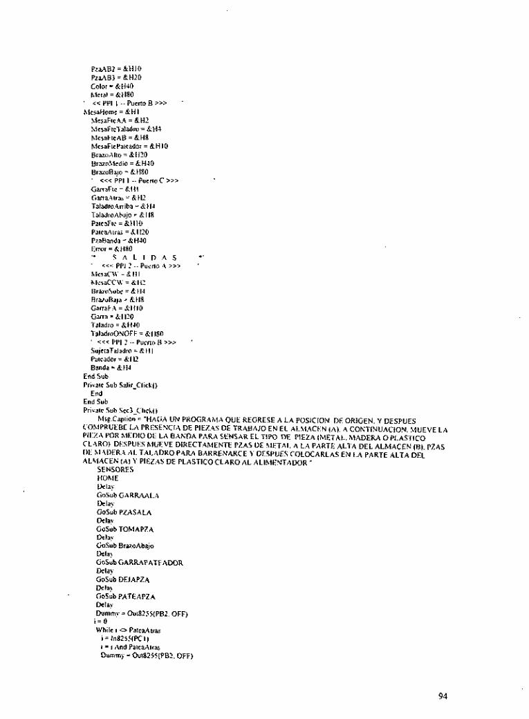
PraAB2 =&HI0
Calor = &U40 Metal = &U80
' cc PPI I - . h e n o B >>> ' MesaHome =&HI
PZaAB3 =&tun
M e d i e A A =&HI hlcsafieTaladro = &Ha MesaFieAB = &H8 hlesaFicPaieador = &HI0 BramAlio = 8H20 BruoMcdiO = &H.IO BraroRajo = &H80
GarraFie = &li I Carra.4iras = &Hz TaladroAniba = &H1 TaladroAbajo = &If8 PatcaFie = &HI0 PaieaAiras = &H20 PzaBmda =&HJO Enor = BHRO '* S A L I D A S .1
' <<< PPI 2 -- puino ,A >>> ' RleraC\I' = & H I hleraCC\v = 8132 13r2Zosube = k t14 Braroflaja = &ti8 GmaF:\ = &li I O urna = &HX Taladro = &H.Iü TaladroONOFF = &I180 ' <<< PPI 2 -- pucno fl >>> ' SujeiaTaladro = 8111 Pairador = &H2 Banda = 8 H . I
' c<c PPI I -- Putno C >>>
End Sub Private Sub Salir-Click()
End End Sub Privaic Sub sec iC l iCk( )
h1rg.Capiion = 'HAGA üh PROGRAMA QUE REGRESE A LA POSICION DE ORIGEN. Y DESPUES COhIPRUEBE LA PRESENCIA DE PIEZAS DE TRABAJO EN EL ALMACEN (A). A CONTINUACION. MUEVE LA PIHZA POR MEDIO DE L A BANDA PARA SENSAR EL TIPO DE PIEZA (METAL. MADERA O PLASTIC0 CL.4RO1, DESPUES hlUEVE DIRECTAMENTE PZAS DE hlETAL A LA PARTE ALTA DEL ALMACEN (0). PZAS Dli AI:\IXRA AL TALADRO PAR4 BARRENARCE Y DESPUES COLOCARLAS EN L A PARTE ALTA DEL ALhlACEN (Al Y PIEZAS DE PLASTIC0 CLARO AL ALIMENTADOR."
SENSORES HOME Dclay GoSub GARR.bi1.A Delay GoSub PZASALA Delay CoSubTOMAPZA Dela?. GoSub BruoAbaio
TioSibGARR4PATEADOR Delay GoSub DEJAPZ.4 Dela) üoSub PATEAPZA Dela) Dummy = OutK2SS(PBZ. OFF)
i - O While i o PaieaAlras
i = In82Si(PCI) i = i And PaieaAtras Dummy - Oui8255(PB2. OFF)
94

Wend GoSub Banda IfSENSORl = I men
FMetal.Virible = TNC Mrg.Capiion = "SE HA DETECTADO METAL" Dummy = OuiaZjS(PB2. OFF) Dela) GoSub GARRACCW Dela! GoSub TOMAPZA Dela! GoSub GARRAALB Delay Gosub RrazoAniba Delay GoSub PZASALB Delay GoSub DEJAPZ4 Delay HOME
lfSENSOR2 = I lñen Elre
FPlaslica.Viiible = True hlrg Caplion = "SE HA DETECTADO PLASTIC0 CLARO Dumm) = Oui8255(PB2. OFF) rk.il\
Gosub GARRACCW Dela! GoSub TOhfAPZA Delay &Sub GARRAPATEADOR Dela!' GoSub DEJAPZA Del'?! HOME
FMadcra.Virible = TNe Mrg.Capiion = "SE HA DETECTADO MADERA" Dummy = Oul825j(PB2. OFF) Delay GoSuh GARRACCW Delay &Sub TOMAPZA Dela). GoSuh GARRATALADRO Delay GoSub DEJAPZA Dumm! = Oui8255(PB?. SujeiaTaladro) GoSub Taladro
Elre
'SIJJET.4 ILA PIE:?..\ I':\K:\ 'I:\I . . \I>K.\K
Dummy = Ou182SS(PB2. OFF) Dela: &Sub TOMAPZA Delay G o S u b G A W L A R E V &la' &Sub BrazaArriba Dela!. GoSub PZASALADEJA Delay Gosub DEJAPZA Delay HOME
'LIBERA LA riEz..<
End I f End If
PATEAPZA: '*** EMPUJA LA PIEZA A LA BANDA TRANSPORTADORA *** h = O While h o PaleaFte
h=ln825S(FCI)
95

h = h And PateaFie Dummy = Ou18255(PB2. Pateador)
Wend Reiurn
Banda- "** ARRANCA LA BANDA DETECTA MATERIAL Y LA PARA CON EL SENSOR DE FíN DE BANDA **' SENSOR1 = O SENSOR2 = O ,Y = o 5 = O S I = o s 2 = 0 While \(. c> PzaBanda \I = I"825í(PCI) u = .And PzaBanda i = In825i lPnl) SI = 5 And hieial S? = I And Color l í S l = hieialThen
SENSOR1 = I Else
ITS? = Color Then SENSOR2 = I
lind I i End If I>urnm! = Oui8255(PB?. Banda)
\\End Reium
TOMAPZA. ' *** TOMA LA PIEZA DE CUALQUIER POSICION * * * \c = o Hhilc u Cz GarraFie I\ = I"8?5%PCI) u = ss And CiarraFic Dummy = Oui8?2i(PM. GarraFA)
Ucnd
Dummy = Ou1825j(PM. Garra) Ueh)
&la!. Rcium
DEJ.4PZ.4: '"* COLOCA ILA PIEZA EN CUALQUIER POSICION * * a
\, = o Whik v GarraFie u = In8:5ilPCI) H = u And GarraFie Durnrn? = OuiS2i5(PAZ.GanaF.4 +Garra)
Wend &lar. Dummy = Out82?5(PAz. OFF) CCl.3)
Rcium
Taladm: I**' BARRENA IJNA PIEZA DURANTE 2 SEGUNDOS *.* a = o \ihilc q <> TaladroAhajo
q = In8255(PCI) q = q And TaladroAbajo Dummy = OuiS?SJ(PA2. Taladro + TaladmONOFF)
Wend &la?. Dummy = Ou1825S(PA2. TaladroONOFF) q = o While q <> RaABl
q = InSZSXPAI) q = q And RaABl
96

Dummy = Ou18255(PAz. TaladmONOFF) Wend Dummy = OutR255(PA2. OFF) 'APAGA EL TALADRO
Return
Brazo Abajo ' * * * MUEVE EL BRAZO HACIA LA POSICION DE ABAJO ***
\\hile q <> BrazoBajo q = ln82SXPBI) q = q And BrazoBajo Dummy = Ou18255(PA2. G a m a + BrazoBaja)
q = o
\Vend Durnmt = Ou182?5(PAZ. Garra)
Return
BrazoAniba: '**' hlUEVE El. BRAZO HACIA LA POSICION DE ARRIBA *'* q = o Nhilc q <> BrazoAllo
q = InR255(PBl) q = q And BrazoAlio Dummy = Ou18255(PAz. Garra + BrazoSuhe)
\ \end Dumm? = Oui82?5(PAZ. Garra)
Return
G..\RR:\:\L-\: "*' I.I.EVA 1.A G,ARF.A AL ALMACEN A *.. While p <> MesaFieAA
p = lnR255(PB I ) p = p And MeraFierZA Dumm? = Ou18255(PA2. McraCW)
p = O
Wend Dummy = Out825i(PA2. OFF)
Reium
GARRAALAREV I * * * LLEVA LA GARRA AL ALMACEN A * * *
While p <> McraFieAA p = In825?(PBI) p = p And MeSaFieAA Dummy = Oui82?5(PAz. MerCCW)
p = O
Ucnd Dumm?=Ou18?55(PA2. Garra)
Rciurn
GARR.A.4I.B:
p = O "*' LLEVA LA GARRA AL ALMACEN B * * *
N'hllc p O MesaFicAB p = ln825S(PBI) p = p And hlrraFteAB Dummy = Oul8255(PAz. Gana + McraCW)
Wend Dummy = Ou182SS(PAZ. Gana)
Rciurn
GARRAPATEADOR: '**' LLEVA LA GARRA AL ALIMENTADOR DE P l U A S *'.
Whilc p o McraftcPaicador p = ln825S(PBI) p 5 p And McsaFlcPaieador Dummy = OuiR25S(PA2. Garra + MesaCW)
p = O
Wend Dummy = hiiS25S(PAZ. Gana)
Return
97

GARRACCW: '*** REGRESA ,A POSICION CCW *** X = O \\hile X <> hiesaHome X = In8255(PBI) X = X And MeraHome Dummy = Ou182SS(PA2. MesaCCU:)
Dummy = Ou18255(PA2. OFF) \\'end
Return
GARRATALADRO "*' LLEVA LA PIEZA AL TALADRO * O *
\\hile p hlesaFirTaladro p = In8?IS(PDI) p = p And MesaFieTaladro Dummy = Oui8255(PA?. Garra + MesaCW)
p = o
Wend Dumm? = Oui82iS(PA2. Gana)
RCi"rn
PZ;\SALB: '"* SELECCIONA W LUGAR VAClO DE ARRIBA HACIA A B M 0 * * * q = In825C(PAI) q = q And P ru iBI I l q oPza. \BI Then
Elvi GoTo REG
,Y 5 o While w o BrazoMedio u = In8?5?(PRI) u = w And BrazoMedio Dummy = O u i 8 2 j I ( P ~ Z . Gana + BraroBaja)
Wend Dumrn! = Oui8?5S(PAZ. ~ a r r a ) Dela? q = ln8255(P.~1) q = q And RaAB2 I f q 0 P a 4 8 2 Then
Else &To REG
,I = o While w <> BraroBsjo
= l"82"(PB I J
u = w And BmoBajo h m m ? = O u i 8 2 I 5 1 ~ ~ 2 . ana + B ~ z o B ~ ~ ~ )
h m m ? = Oui8255(PA2. Gana) ! M a ) 9 = ln8251(PAI) q = q And Pza4B3 I lq <> RaAB3 I k n
Wend
GOTO REG End If
End If End I f
REG: Rcrurn
PZASALA: '"* SELECCIONA UNA PIEZA DE ARRIBA HACIA ABAJO * * * q = ln82SS(PAI) q = q And PzaAAl Ifq=PraAAl Then
GoTo REGRESA E l u
u . = O While u 0 BraroMcdio u. = In825S(PBI)
98
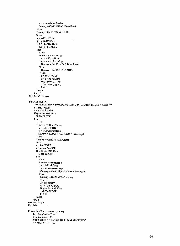
w = w And Brazohicdio Dummy = Oui82jj(PA2. BrazoBaja)
\\end Dummy = Oui8?55LPA2. OFF) Dela) q =In8?55(PAi) q = q .And Pi.aAB2 I f q = PzaAU2 n e "
GoTo RCCRESA
,, = o While \I <> BrazoBajo
Else
z = ln825XPBI) \I = <I .And BmoBajo Dummy = Oui8255(PM. BrazoBaja)
Dumm! = Oui8255(PA2. OFF) Vela? q = I"8ZS1lPAI) q = q And PiaAB3 i r q = ~7.2403 n e n
ci ir0 REGRESA
Wend
End I f
P%ASAI.ADEJ..\. '*" Slll.1iCCIONh UN LUGAR VAClO DE ARRIBA HACIA ABAJO * * * q = In8?55(PAll q = q And P d B i l f q c> PzaABI Then
COT« KEGKE Elre ,, = o
While (I c> Rrazohlcdio iv=ln82II(PBI) u = u And BrazoBajo Vumm! = Oui8255lPA2. Garra + Brazoüaja)
Wend Dummy = Oui8255(PAZ. Garra)
&la? q = ln82151P,\I) q = q And &&AB2
CmTo RllGRfi
,I = o While u <> BrazoBajo
i r q <> ~ ~ 4 ~ 2 nen
Elre
H = In8?!5íPBI) w = w And BrazaBajo Dummy = Oui8255lPAZ. Garra + BrazaBaja)
Wend Dumm) = Oui82551PAl. Garra)
k l a ! q - ln8255IPAI) q = q And PraAAl I fq <> ReU3 l ñ c n
GOTO REGRE End If
E ~ J ir End If
REGRE Rrium End Sub
Rivaic Sub Tcrv\lmacrnes_Click() Mrg.FoniRold = Tmc Mre.FoniSizc = 35 h!Sp.Capiiün = .PRUEBA DE LOS ALMACENES' TlhU.Enabled = TNC
99

' HOME '**I CHECA POSIONES DE LOS ALMACENES '** '*** CHECA ALMACEN A L = ln8215(PAI) v = z And PzaAAl Ifi. = RdAl Then
LedAI.FillColor = LedON LedN.FillCalar = LedOFF ~
LedM Fillcolor = LedOFF hlse Capiton = 'PIEZA ALhl4CEN (A) ARRIBA" Dela! PZA = I
v = z And Pza4.42 I f Y = Pzak42 nhcn
Else
Led,Q.FillColor = LcdON Lrd.U.FillColoi = LedOFF hisg.Capiion = "PIEZA ALMACEN (A) ENMEDIO Dela! PZA=2
v = 7 And P m M 3 I f v = prSA.43 Then
Else
I.id.43 FillColor = LedON hkg Capiion = 'PIEZA ALhlACEN [A) ABAJO I)&\ PL.4 = 3
End If End lí
End If ir PLA > o nen
h1q.Capiion = "TIENES " + PZA + " PIEZA(S) EN EL ALMACEN A"
hlsg.Capiion = " NO TIENES PIEZAS EN EL ALMACEN A" Elre
End I f
@I.??. PZA = o "'* CHECA ALhiACEN B *** z = ln8255(PAI) k = z And PraABl If L = R.aABI Then
LcdBl.FillCalar = LrdON I.edH2.FillColor = LcdOFF LrdB3.FillCalor = LedOFF hlrg.Capiion = 'PIEZA ALhlACEN IB) ARRIBA' D&) PZ.4 = I
L = L And PzaAB? If k = pr&4B? n c n
Else
LrdB2.FillColor = LrdON LcdB3.FillColor = LcdOFF Mse.Capiion = 'PIEZA ALhlACEN (R) ENMEDIO Del?.! PZA = 2
k = z And PraAB3 I fk=PzaABI mcn
Elw
LcdB3,FillColor = LzdON Mrg.Capiion = 'PIEZA ALMACEN (8) ABAJO'
PZA = 3 Delay
End If End If
End If If PZA > O Then
Mrg.Capiion ="TIENES " + PZA + " PIEZA(S) EN EL ALMACEN B" El= hlsg.Capiion = "NO TIENES PIEZAS EN EL ALMACEN B'
1 O0

End I f Delay LedAI.FillColor = LedOFF LedAIFillColor = LedOFF LedAi.FillColor = LcdOFF Lcdül .FillCalor = LedOFF LedB2.FillColar = LedOFF LedB3,FillColor = LcdOFF
End Sub
Private Sub TertAII_Click() hlsg.Aliynent = 2 Msg FantBold =True h4sg.FoniSizc = 35 Mrg.Caption = "PRUEü.4 DE LAS SALIDAS A LOS ACTUADORES DEL IilOL>EI.O I: :\
' HOME GoSub TeriMrsa &lax GoSub TesiBraro Delay GoSub TertGma &la!. &Sub TestTaladro &la> GoSub TestPatcador Dela? GaSub TestAlmaccnes D d a > GoSub TcrtBanda hlsg.Caplion = "SE HAN FINALIZADO LAS PRUEBAS"
End Sub
Private Sub TcsiBanda-Click() Mrg.Alignrnent = 2 Msg.FontBold =True Msg.FomSize = XI Tlhl3.Enabled = True Mrg.Capiion = "TEST A BANDA"
' HOME X = O Mrg.Capiion = "Banda cn marcha'
While c <> PraBanda S = ln8255(PCI) X = X And Pmñanda h m m ? = Oui8251(PBZ. Banda) PBArranque.FillColor = LedON PBPar0.FillColor = LedOFF
Dummy = Out8?5C(PB?. OFF) PRAnanquc.FillCalor = LcdOFF PBPm FillColor = LedON hlsg.Caption = 'Pieza al find de la banda"
PBArranque.FillColor = LcdOFF PBPm.FillColor = LcdON
Wrnd
Dela)
End Sub
Privatc Sub TcsiBruo_Click() Mrg.Alignmeni = 2 Msg.FoniBold = Tmc Msg.FonlSizc = 40 Mrg.Caption = "TEST AI HUSILLO DEL BRAZO'
Mrg.Caption = "Inicia la prueba' Lcdh1edio.FillCalar = LcdOFF LcdAbajo.FillColor = LcdOFF LcdAniba.FillColor = LcdON &Sub ABAJO TlMlEnablcd =True LcdMcdio.FillColor = LcdOFF
' HOME

GoSub ARRIBA hlrg.Capiion = "Fin de la Prueba"
ABAJO I.** MUEVE EL B R U O HACIA ABAJO *** S=O a=O b=O c = o While c c> BrazoHajo
S = In82Si(PBI) a = S .And BrazoAho b = S And Rramhiedio E = S .And BrivoBajo Ii a = BramAlio Then
LedAniha.FillColor = LedON hlrg.Capiion = "El brazo esta arriba" Tlhl? Enahled =True
I í h = Brazohledio Then Else
Led.4mba.FiIlColor = LedOFF Ikdhiedio FillCdor = LcdON Xlrg.Capiion = "El bruo esta en medio" llhl2,Enabled =Tme
I f c = BraroBajo n e n ElSC
I.edhlrdio.FillColor = LedOFF I.cd.~\bsio.fillColor = LcdON hisg.Capiion = "Brazo esta abajo'
End l i End I f
End I f Ihmrn? = Oui825i(PAi. BrazoBaja) PH.4hajo.FillCnlor = LedON Pü:\niha,FillColor = LCdOFF
Wcnd nurnrn! = OU~X?~((PA~. OFF) PüAhaja.FillColor = LedOFF PBAniba.FillColor = LcdOFF
Rciurn
ARRIBA: '"* hIUEVE EL BR,UO HACIA ARRIBA * * * s = n ~. a = 0 h = O r - O Whilc c <, Dr&7<ili"
S = In8?%S(PBI 1 a = S And Rrivoüajo b = S And Brazohlrdio E = S And BrazoAlto Ira = BrainRajo Tken
LedAbajo.FillColor = LcdON hlre.Caption 'El brazo e s a abajo' TIMlEnablcd = Tmc
If b = Brarohlcdio Thcn Elw
LcdAbajo FillColor = LcdOFF LcdMcdio.FillColor = LedON hlrg.Capiion = 'El brazo esa cn medio' Tlhl2,Enabled =True
If c = BrazoAlio Then Else
LcdMcdio.FillColor = LedOFF LedAniba.FillColor = LcdON Mrg.Capiion = 'El Bra20 csia arriba'
End I f End Ir
End If
I02

Dummy = Ou18255(PA2. Brazosuhe) PBAbajo.FillColor = LedOFF P8Arriba.FillColor = LedON
Wend Dummy = 0~1825SlPA2. OFF) P8Abajo.FillColor = LedOFF P8Arriba.FillColor = LedOFF
Return PBAbajo FillColor = LedOFF P8Arriba.FillColor = LedOFF End Sub
Private Sub TcaFarra~ClickO hls$.Alignmcnt = 2 hlr$.FoniBold = True h l s ~ . F n m S i x = 40 hli$.Caption = 'TEST A LA GARRA"
hlse.Capiion = "Inicia l a prueba" h m m y = O~i8255iPA2. GarraFA) PUFrenic.FillColar = LrdON P8Atrm.FillColor = LedOFF
' tlOhlE
hire Caption = " L a Garra esta Extendida' Tlhl3,llnabled = T N ~ I h m m ? = Oui8255iPAZ. GarraFA + Garra) PGCerrar.FillCdor = ILedON P(i:\hrir.FillColor = LrdOFF hlsg Caplion = 'La Garra esta Cerrada" Tlhl3,Enablrd =Tmr »umm) =Oüi8?5%PAZ. GarraFA) PGCerrar.FillCalor = LedOFF PGAbrir.FillColar = LcdON hlrg Caption = 'La Garra e m Abiena" TIMl.l~nablcd = T N ~ Dummy = Oui8ZSSiPAZ. OFF) PBFrenic FillColor = I.edOFF PU.\irar.FillColor = LedON hlrg.Caption = 'La Garra esla Reuaida" PDFrenie.FillColor = LcdOFF PBAiras FillColor = LcdOFF PCKerrar.FillColor = LrdOFF PGAbrir FillColor = LedOFF
End Sub
Privaic Sub TcrNcraClick() hlsg .\lignmint = 2 hlsg FantBald = T N ~ hlrg F"n1Size = 40 hlsg.Capiion = "TEST A L A MESA GIRATORIA'
hlsg Caption = *Inicia l a pmcba' hlCCW.FillColar = LedON hlAA.FillColor = LcdOFF hlT.FillColor = LcdOFF hlA8.I~ilIColor = LedOFF hlCW.FillColor = LcdOFF CoSub hlOV CW
' IIOME
TIM2 Enablcd =True %Sub hiOV-CCU' hlrg Cuplion = 'Fin de la Prueba'
h lOVCW "" AVANZA A POSICION CW o * *
X = O a = 0 h = O C = O
d = O
I03

a = X And McsaFteAA b = X And MesaFtéTaladro c = S And MesaFteAB d = X And MeraFiePateador Ifa = h4esaFteAA ihcn
hlCCW.FilIColor * LedOFF h4AA.FillColor = LedON Ms$.Caption = "Mesa frente al dmacen A' Tlhl2,Enabled = TNC
If b = MesaFicTaladro Then MAAFillColor = LedOFF hlT.FillColor = LedON hlsg.Capiion = "Mesa irenic ai Taladro' TIht?.Enabled =TNe
I f c = hlesaFie.4U Then
Else
Else
hlT.FillColor - LedOFF hlAB.FillColor = ladON Ms:.Caption 3 "Mesa frcnie al almacen E" Tlhl? Enabled = True
Elre I f d = hkraFiePaieador Then
hl,\B.FillColor = LedOFF MC\V.FillColor = LedON hlsg.Capiion = "hlesa frente al patcador"
End If lind If
End I f End I f I>umm! = OuiS?jS(P:\?. h i e d \ \ ' ) PhIC\V.FillColor = LedOFF PMCCW.FillColor = LcdON
Dummy = Oui8XXPA2. OFF) Wend
RciWTI
MOV-CCW: "'* AVANZA A POSICION CC\\' **' S = 0 .3=0 b = O c = o d=O Whiled 0 hlesatiomc X = InSZSS(PRII a = X And McsaHome b = S And hlersFtcAA c = X And hlrsaFieTaladm d = S And McraFicAR l i d = McraFicAR Then
hlCW.FillColor = LcdOFF hlAB FillCalor= LcdON hlrg.Cqiion = "Mcsa frente al almacm 0" TlhQEnablcd = Tnie
I f c = hicsaF~cTdadroihm hlAB.FillCalor = LedOFF MXFillColor = LcdON hlse.Caplion = 'Mesa frcnic al Taladro' TIhl?.Enablcd = TNC
i f b = 1hlcsaFick4 Then
Elw
Elre
hlT.Fil1Colar = LcdOFF M.4A.FillColor = LcdON Msg.Capiion = "Mesa fmic al almacm A' Tlhl2.Enablcd = TNC
I f a = h l c d o m c The" Else
hlAA.FillColor = LcdOFF
104

hlCCW.FillColor = LcdON Mse.Caoiion = ''Mesa en HOME'
End ii End If
End If End I f Dummy = Oui8255(PM. MesaCCW) PMCW.FillColor = LedOFF PMCCW.FillColor = LedON
Dummy = Ou18255(P42. OFF) Wcnd
Return PhlCWFillColor = LedOFF PhICCH'.FillColor = LcdOFF End Suh
Private Sub TertPatcador~Click() hlrg..ilignmrni = 2 hlse.Fantllold = TNC . hlsg.FontSize = 4 0 Tlhl3,Enablcd =True hlsg Caption = "PRUEBA DEL ALIMENTADOR DE PIEZAS A LA BANDA" Q = O tkhilc q u PatcaFic
q = ln8211fPCI) q = q And I>atraFtr I>umm! F OutR?!i(PB2. Patcador) PPFrrnic.FiIlCalor = LedON PP.,\lru Fi l lCdor 5 LcdOFF
\\end Mrg Caption = 'Patcador extendido' Del.??. While q <> Patea4tras
q = l"825ilPCI) q = q And PatraAtru Dummy = Oul8?!Z(PB?. OFF) PPFrcntc.FillColor = LcdOFF PPAtrar.FillColor = LedON
Wcnd hfrgcaption = 'Patcador rclraido" Delay PPFrenie.FillColor = LedOFF PP:\irar.FillColar = LsdOFF
End Sub
Privair Suh TcrtTaladro_Clicl() h i r g . A l i p ~ m t = 2 hlrg FontRold = TNC Msg.Fon1Sii.c = 40 TlhlS Enahlcd = TNC hlsg.Caption = 'TEST .A L A ESTACION DE BARRENADO"
"'* BARRENA UNA P l U A DURANTE 3 SEGUNDOS * * *
\Ililc q o TaladmAbajo q - 0
q = ln82SXPCI) q = q And TaladmAbaia DUmm? = OuI8???iPA?. Taladm + TaladroONOFF) PTAbalo FiIIColor = LcdON PTAniba FlllCalor = LcdOFF
Wrnd hlsg.Caption - "Taladm Abajo y barrenando' Delay hvlIm) = Ou18255(PAi. TdadroONOFF) q = o Whilc q 0 TaladmAniba
q = ln8255(PCI I q = q And TaladraAniba h m m ? =Ou18?55(PAi. TaladroONOFF) KAbajo.FillColor = LedOFF
I os
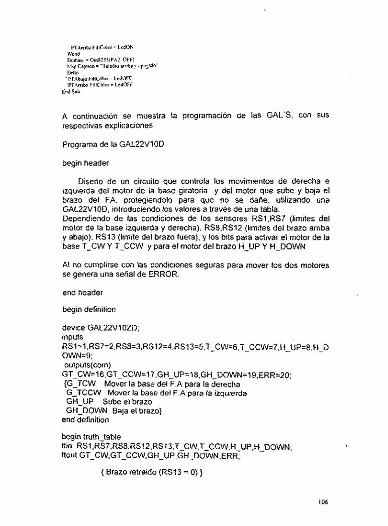
PTAniba.FillCalar = LedON Wend Dummy = Ou18255(PA2. OFF) Msg.Caption = "Taladro arriba y apagado" Dela)
' PTAbajo.FillColor = LcdOFF 'PTAniba.FillC0lor - LedOFF
End Sub
A continuación se muestra la programación de las GAL'S, con SUS
respectivas explicaciones:
Programa de la GAL22V10D
begin header
Diserio de un circuito que controla los movimientos de derecha e izquierda del motor de la base giratoria y del motor que sube y baja el brazo del FA, protegiendolo para que no se dañe, utilizando una GAL22VIOi3, introduciendo los valores a través de una tabla. Dependiendo de las condiciones de los sensores RSI,RS7 (limites del motor de la base izquierda y derecha), RS8,RS12 (limites del brazo arriba y abajo). RS13 (limite del brazo fuera), y los bits para activar el motor de la base T-CW Y T-CCW y para el motor del brazo H-UP Y H-DOWN
AI no cumplirse con las condiciones seguras para mover los dos motores se genera una señal de ERROR.
end header
begin definition
device GAL22VlOZD; inputs RSl=l,RS7=2,RS8=3,RS12=4,RS13=5.T-CW=6,T - CCW=7,H_UP=8,H - D OWN=9; outputs(com)
GT CW=16,GT CCW=17,GH-UP=18,GH-DOWN=19,ERR=20; {GITCW Mover la base del F.A para la derecha G-TCCW Mover la base del F.A para la izquierda GH-UP Sube el brazo GH-DOWN Baja el brazo}
end definition
begin truth table ttin RSI.R~7.RS8.RS12,RS13,T-CW,T-CCW,H-UP,H - DOWN; ttout GT-CW.GT-CCW.GH-UP,GH-DOWN.ERR;
{ Brazo retraido (RS13 = O) }
I06

{ Sensores R S I y RS7 limites de la base} O000 O O000 O000 0 0000 O 0100 O100 O O000 O 1000 I000 O 000001100 00001
100000000 00001 100000100 00001 1000 o 1000 1000 1 100001100 00001
010000000 00001 010000100 01001 010001000 00001 010001100 00001
{ Actuadores T-CW y T-CCW } { Error = 1 desctiva el buffer 6) {de los otros actuadores}
O000 O O001 0001 O {Sensores RS8 y RS12 limites del brazo} O000 O O010 0010 O O000 O 001 1 O000 1
001000000 00001 001000001 0001 1 001000010 00001 001000011 O000 1
{ Actuadores H-UP Y H-DOWN } { Error = 1 }
000100000 00001 000100001 00001 000100010 O0101 000100011 O000 1
{Brazo fuera RS13 = I}
O000 1 O000 O000 O {Sensores RS1 y RS7 limites de la base} O000 1 0100 O000 1 { y } Actuadores T-CW T-CCW O000 1 1000 O000 1 {Error = 1 desactiva otros actuadores} 000011100 00001
100010000 00001 100010100 00001 100011000 00001 100011100 00001
010010000 00001 010010100 00001 010011000 00001
I07

010011100 00001
000001011 00001 000001101 00001 O000 o 11 10 O000 1 000001101 00001
end truthtable
Disposición de la GAL22V1 OD OPL2PLA - OPAL design entry compiler V008 Copyright (c) National Semiconductor Corporation 1991 Input Pins
Pin name pin number arch visible default
_ _ _ _ _ _ - _ _ _ _ _ _ _ _ _ _ _ _ _
- - - - - _ - -_-_ _ - _ _ _ - _ _ _ _ _ - - _ - _ _ _ _ _ _ RS 1 RS7 RS8 RS12 RS13 T CW T-CCW HIUP
1 2 3 4 5 6 7 8
corn corn corn corn corn corn corn corn
visible visible visible visible visible visible visible visible
.)
- _ _ _
I08
O000 1 O001 O000 1 {Sensores RS8 y RS12 limites del brazo} O000 1 O010 0000 1 { Actuadores H-UP Y H-DOWN } 000010011 00001
001010000 00001 O010 1 O001 0000 1 001010010 00001 0010 1 O011 O000 1
O001 1 O000 0000~1 000110001 00001 000110010 00001 0001 1 O011 O000 1
{Brazo retraido RS13 = O }
O000 O O101 O101 O{Sensores RSI y RS7 limites de la base} O000 O 0110 0110 O {y RS8 y RS12 limites del brazo} O000 O O 1 11 O000 1 {Actuadores T-CW, T CCW, H-UP y H DOWN} O000 O 1001 1001 O {Combinacion de las tablas anteriores}- 000001010 10100

H-DOWN 9 corn visible
Output Pins
Pin name pin number arch visible default
- - - GT-C W 16 corn visible
-__-_-_--== ___-_-- - -
- - - - - - - -__------- -_-- ------- -
rst GT-CCW rst GH-UP
17 corn visible
18 corn visible rst
rst ERR 20 rst
GH-DOWN 19 corn visible
corn visible
EQN2JED - Boolean Equations to JEDEC file assembler (Version V024) Copyright (c) National Semiconductor Corporation 1990,1991
Document file for GALI-FA.eqn Device: G22V1 O
$LABELS 24 R S I RS7 RS8 RS12 RS13 T-CW T - CCW H - UP H - DOWN nc nc GND nc nc nc GT-CW GT-CCW GH-UP GH-DOWN ERR nc nc nc VCC
Pin
1 2 3 4 5
---
6 7 8 9 16 17 10 19 20
Label Type ----_ ---_ RSI pos.com input RS7 pos.com input RS8 pos,com input RS12 pos,com input RS13 pos,com input T-CW pos.com input T-CCW pos.com input H-UP pos.com input H-DOWN pos,com input GT-CW pos,trst,com output Gi-CCW pos.trst,com output GH-UP pos,trst.com output GH-DOWN pos.trst.com output ERR pos,trst,com output
EQN2JED - Boolean Equations to JEDEC file assembler (Version V024)
I09

Copyright (c) National Semiconductor Corporation 1990,1991
Device Utilization:
No of dedicated inputs used No of feedbacks used as dedicated outputs : 5/10 (50.0%)
: 9/12 (75.0%)
_____________________-- -_-_-_-_-- -_-__-- -_ Pin Label Terms Usage
20 ERR 13/15 (86.7%) 19 GH-DOWN 4/17 (23.5%)
17 GT-CCW 4/15 (26.7%) 16 GT-CW 4/13 (30.8%)
Total 291132 (22.0%)
__________-__-______-__-__- -__-__- -_- - - - - -
18 GH-UP 4117 (23.5%)
_-__-___-_-___-_____-____--_--__--__-_--__
------_--_---_______-___-___-_-----_--_-_- EQN2JED - Boolean Equations to JEDEC file assembler (Version V024) Copyright (c) National Semiconductor Corporation 1990,1991
C h i p d i a g r a m (DIP)
RS7 I 2 RC8 I 3 RS12 I 4 RS13 I 5 T C W I 6
T - ?CW I 7 H U P I 8
I 1 0 I 11
GND I 12
H - DOWN I ~9
23 I 22 I 21 I 20 I ERR 19 I GH DOWN 18 I GH-UP 1 7 I GT-ccw 16 I GT-cw - 15 I 1 4 I 13 I
I I Programación de la GALl6V8Z
begin header
Diseño de un circuito para protección del brazo del F.A el cual no Saldra fuera si se encuentra enfrente del taladro y ademas en la parte alta o parte media del husillo utilizando una GAL16V8Z.introduciendo los valores a traves de una tabla.
RS4 Sensor mesa frente al taldro RS9 Sensor parte alta del husillo
110

RSlO Sensor parte media del husillo H-FB Activacign del brazo
H-FB = 1 Brazo fuera H - FB = O Brazo retraido
end header
begin definition
device GAL16V8; inputs RS4=1 ,RS10=2,RS9=3,H_FB=4; outputs(com) GH_FB=12;
end definition
begin truth-table ttin H_FB,RS4,RSlO,RS9; ttout GH-FB;
O000 o O001 o O010 o O011 o O100 o O101 o O110 o o111 o
1 O00 1001 1010 1011 1100 1101 O {Brazo frente al taladro y parte alta del husillo} 11 10 O {Brazo frente al taladro y parte media del husillo} 11 11 O {Condición inexistente}
end truth-table
Disposicion de la GAL16V8Z OPL2PLA - OPAL design entry compiler V008 Copyright (c) National Semiconductor Corporation 1991 Input Pins --_-_--___ --_--_-___

Pin name pin number arch visible default
RS4 1 corn visible RSlO 2 corn visible RS9 3 corn visible H-FB 4 corn visible
- - - - - - - -___ - _ - - - - - - - - - - - - - _-____-_--
EQN2JED - Boolean Equations to JEDEC file assembler (Version V024) Copyright (c) National Semiconductor Corporation 1990,1991
Document file for GAL2-FA.eqn Device: 16V8
$LABELS 20 RS4 RSlO RS9 H-FB nc nc nc nc nc GND nc GH-FB nc nc nc nc nc nc nc VCC
Pin Label Type --- _ _ - _ _ - _ _ _ 1 RS4 pos,corn input 2 RSlO pos,corn input 3 RS9 pos,corn input 4 H-FB possorn input 12 GH-FB pos,com output
112

EQN2JED - Boolean Equations to JEDEC file assembler (Version V024) Copyright (c) National Semiconductor Corporation 1990,1991
Device Utilization:
No of dedicated inputs used : 4/10 (40.0%) No of dedicated outputs used : 1/2 (50.0%)
---_--___---__--___--------_----_--------- Pin Label Terms Usage
EQN2JED - Boolean Equations to JEDEC file assembler (Version V024) Copyright (c) National Semiconductor Corporation 1990,1991
Chip diagram ( D I P )
- I
R S 4 I 1 RSlO I 2
R S 9 I 3 H F B I - 4
1 5 1 6 1 : 1 8 1 9
GND I 10 12 I GH - F6 11 I

4.2 Operación del prototipo
El prototipo debe operarse siempre y cuando se encuentre instalado correctamente, es decir: a) Debe estar sobre una base fija que no presente vibraciones y que este
nivelada. b) La clavija no debe estar maltratada para que haga buen contacto en el
toma corriente y no haya falsos contactos que pudieran daiiar el sistema.
c) La presión del aire debe ser mínimo de 6 bares.
4.3 Calibración y ajustes
En el caso de requerir ajustar algunos puntos de los mecanismos del FA, a continuación se indican los modos de proceder:
Banda transportadora:
Se cuenta con unos tornillos tensores en un extremo que se ajustan si la banda se afloja.
Mesa giratoria:
Esta se apoya en 4 soportes con rodamientos sobre los cuales gira la mesa central. En los extremos de estos soportes existen tornillos que permiten subir o bajar los rodamientos y al nivelarlos se restablece la verticalidad de la mesa central. Esta operación debe hacerse con suma precaución, nivelando previamente el FA sobre una superficie firme y utilizando un nivel de precisión. Para tener acceso a estos soportes se requiere retirar el equipo electrónico colocado dentro del FA lo que debe hacerse con las precauciones debidas.
Interruptores de Limite ( I.L.):
Todos los I.L. son activados por un puntero que se mueve junto con la mesa y con el brazo manipulador. Tanto los punteros como los I.L. están montados sobre bases con ranuras que en caso de necesidad se mueven aflojando los tornillos sujetadores y deslizando el I.L. o el puntero a la nueva posición.
Sensores: Los sensores Optico y de metal se entregan calibrados. Si se requiere algún reajuste, se anexan en este trabajo las hojas técnicas del proveedor.
Equipo Eléctrico y Electrónico:
I I4

Estos componentes no requieren calibración por el usuario. Cualquier reajuste debe hacerlo un profesor conocedor del equipo y con la documentación técnica que se anexa.
4.4 Mantenimiento
El FA, requiere de un mantenimiento mínimo para su seguro y adecuado funcionamiento a lo largo del tiempo. Lo expondremos en los siguientes puntos:
Limpieza externa:
Se recomienda limpiarlo una vez por semana exteriormente con una franela limpia y seca para retirar el polvo ambiental. Las manchas debidas a la grasa de las manos del usuario, se pueden limpiar con una franela ligeramente humedecida con agua jabonosa y después con franela seca. Las partes móviles de la garra y los rodamientos de la mesa giratoria se deben aceitar con una gota de aceite delgado (3enl) una vez por mes. El aceite que escurra debe limpiarse inmediatamente.
Limpieza interior:
Se sugiere utilizar aire seco, sin gotas de grasa, de preferencia con un "spray" para limpieza de computadoras, ya que si el aire proviene de un compresor común, contiene pequetias gotas de aceite que con el tiempo provocarán fallas en los circuitos electrónicos,
Equipo neumático:
Revisar una vez por semana que no existan fugas de aire en las conexiones de las mangueras.
Revisar el nivel de aceite antes de cada práctica en la Unidad de Mantenimiento y si faltara, reponerlo con aceite para equipo neumático hasta la marca del depósito de aceite.
Probar el compresor y revisar la presión del aire, debe ser de 30 PSI máximo.
Equipo eléctrico:
Conectar el interruptor principal y comprobar que el ventilador interior de enfriamiento funcione, en caso de no funcionar, no utilizar el FA, hasta después de hacerlo funcionar o reponerlo con otro de semejantes características.

Verificar que las luces indicadoras del tablero frontal enciendan, en caso contrario determinar la falla con ayuda de los diagramas electrónicos que se adjuntan.
Sopletear en forma periódica las tarjetas con aire seco.
Cuidados generales:
Se recomienda cubrir el FA con una funda de plástico, no someterlo a golpes, dejarlo siempre apagado al termino de la clase, comprobar que el voltaje sea de 127 VAC, tenerlo en un lugar fijo donde no pueda ser golpeado, mojado o sometido a cambios extremos de temperatura o vibraciones.
En caso de reparaciones, procurar reponer los componentes dañados con otros iguales o de las mismas características. De no ser así, verificar el funcionamiento del FA y hacer los ajustes necesarios.
I16

5. LISTA DE MATERIALES Y COSTOS
5.1 Sistema de control
Esta lista de materiales y costos se desglosó en 7 bloques que incluyen 129 partidas, repartidas en sensores, motores, serigrafia y electrónica las cuales se detallan enseguida:
Lista de materiales y precios de sensores
NO DESCRIPCIÓN PROVEEDOR MODELO UNIDAD PRECIO CANTI PRECIO UNITARIO DAD TOTAL
1 Microsensor OMRON EE-SE5 PZA 4541 1 45 41 fotoeikctnco
2 Microlimit Switch OMRON S S - 5 G L 2 PZA 2090 4 83 60 3 Sensor OMRON E3S-VSlE4 PZA 1,71000 1 1,71000 4 Sensor Limit OMRON D2MC-O1E PZA 91 10 1 91 10
Switch 5 Sensor lnductivo OMRON E2E-XlOE1-N PZA 729.22 1 729.22
SUBTOTAL 2,659.33 IVA 15% 398.9 TOTAL 3,058.23
Lista de materiales y precios de motores
No DESCRIPCION PROVEEDOR MODELO
6 Motor de CD a Servo System CYHC42700-
7 Motor de CD a Servo System CYQC43264-
8 Motor de CD a Servo System CYQC43264-
9 Motor de C.D. a Servo System #1442-O09
12 volts 3 19rpm 66 1
24 Volts. 58 RPM 2-1
24 Volts, 58 RPM 2-1
12V.2500 RPM
UNIDAD PRECIO CANTI PRECIO
PZA 1926.70 1 1926.70
PZA 550.00 1 550.00
PZA 550.00 1 550.00
PZA 135.00 1 135.00
3,161.70 SUBTOTAL IVA 15% 474.25 TOTAL 3,635.95
UNITARIO DAD TOTAL
I I7

Lista de materiales y precios de serigrafia
10 Pantalla de 120 hilos 11 Mascarilla
antisoldante 12 Solder Mask 13 Thiner 14 Estopa 15 Acetato para
impresora 16 Cinta canela 2" , de
ancho 17 Marcador tinta
permanente 18 Pluma de tinta
conductora 19 Alcohol isopropiiico 20 Brocha 1/2 pulgada 21 Solvente
adelgazador plrnascañlla
22 Rapid clean 23 Tablilla fenólica 24 Cloruro fbrrico
(piedra)
No DESCRIPCIÓN PROVEED MODELO UNIDAD PRECIO CANTI PRECIO OR UNITARIO DAD TOTAL
30 X 40 CM PZA 50.00 3 150 O0 Kg. 93.82 0,2 18.76
PZA 1710.00 1 1710.00 L 4.00 5 20.00
CAJA 30.00 I 30.00
ROLLO 7.47 2 14.94
Kg. 5.00 2 10.00
punto fino PZA 12.20 1 12.20
PZA 182.62 1 182.62
L 10.00 1 10.00 PZA 4.52 1 4.52
L 100.00 0.2 20.00
L 100.00 0,2 20.00 30 x30 cm PZA 80.00 5 400.00
KG 50.00 2 100.00
Subtotal 2,703.04 IVA 15% 405.46 TOTAL 3,108.50
Lista de materiales y precios de electrónica
NO DESCRIPCI~N PROVEEDOR MODELO UNIDAD PRECIO CANTI PRECIO UNITARIO DAD TOTAL
25 Circuito integrado PZA 2 3 9 30 71 70
26 Resistencia 10 PZA O30 166 4980 74LS240
Kilohm. 1/4 W
Ohms, 1/4 W
Kilohm, 1/4 W
27 Resistencia 270 PZA 020 166 33 20
28 Resistencia 2 2 PZA O30 100 30 O0

No DESCRIPCIÓN PROVEEDOR MODELO UNIDAD PRECIO CANTI PRECIO
29 Circuito integrado
30 Led rojo opaco 31 Switch giratorio
tres posiciones un polo tres vias
32 Circuito integrado Gal 16V8
33 Circuito integrado 74LS44
34 Terminal con 3 tornillos TRT-03
35 Relevador mecánico, bobina 12 V.C.D. NC, NA, 127 VCA. 1 A.
36 Puente H LMD 18200
37 Circuito integrado 74LSOO
38 Circuito integrado 74LS86
39 Circuito integrado ULN2003EN
40 Diodo 1N40004, 1 Ampere
41 Transformador 11 0/36 VCA, 3 A
42 Transformador 110124 VCA, 3 A
43 Transformador 1 10112 VCA. 3 A
44 Puente rectifcador. 3 A, CP301
45 Capacitor
TPL-521-4
eiectrolitico 2000 uF. a 50 Volts
electrolitico 4700 uF. a 50 Volts
47 Circuito regulador LM350
48 Diodo MR500. 3A. 49 Capacitor 1 uF,
50 Capacitor 0.1 uF.
46 Capacitor
tantalio
tantalio
PZA
PZA PZA
PZA
PZA
PZA
PZA
PZA
PZA
PZA
PZA
PZA
PZA
PZA
PZA
PZA
PZA
PZA
PZA
PZA PZA
PZA
UNITARIO DAD 16.50 30
0.52 33 35.00 1
26.91 5
4.10 5
4.00 20
50.00 9
242.80 1
3.40 1
4.50 1
5.50 2
0.20 2
96.50 1
86.10 1
64.40 1
17.00 3
7.60 2
6.20 1
50.00 1
3.00 3 1.00 3
1.00 3
TOTAL 495.00
17.16 35.00
134.55
20.50
80.00
450.00
242.80
3.40
4.50
11.00
0.40
96.50
86.1 O
64.40
51.00
15.20
6.20
50 O0
9.00 3.00
3.00
I I9

NO DESCRIPCIÓN PROVEEDOR MODELO
51 Capacitor 0.1 uF. cerámico
52 Potenci6metro vertical, 5 Kilohms
53 Resistencia de 240 Ohms
54 Header Molex macho €15-8PV
55 Header Molex hembra E15-8PV
56 Header Molex macho E15-12PV
57 Header Molex hembra €15-12PV
58 Soldadura 60/40 59 Flux para soldar 60 Pasta para soldar 61 Base
autoadherible plcincho
sujetables de 62 Cinchos NO. 96
nylon 63 Portafusible de
cartucho tipo Americano AMPF- 5
americano fusi6n Rápida. 3 A.
65 Switch balancin 1 polo. 1 tiro Piloto ro jode loa15 A.127Q20VCA
64 Fusible tipo
66 Tubo termocontráctil. cal 22
palanca miniatura 1 polo, 2 tiros, 3 posiciones Si, no si, 1 A.
palanca miniatura 1 polo. 1 tiros, 2 posiciones Si. no,
69 Banana o hembra
67 Interruptor de
68 Interruptor de
1 A.
philips rojo
UNIDAD
PZA
PZA
PZA
PZA
PZA
PZA
PZA
ROLLO 1/4 L PZA PZA
BOLSA
PZA
PZA
PZA
m
PZA
PRECIO CANTI PRECIO UNITARIO DAD TOTAL
1.00 3
2.00 3
0.30 3
4.90 1
2.40 1
3.50 1
5.50 1
52.00 1 29.00 1 29.00 1 4.50 25
100.00 1
2.70 1
1.10 2
10.90 1
3.50 2
8.80 3
3.00
6.00
0.90
4.90
2.40
3.50
5.50
52.00 29.00 29.00
112.50
100.00
2.70
2.20
10.90
7.00
26.40
PZA 10.10 8 80.80
250-570R PZA 2.75 8 22.00
I20

NO DESCRIPCIÓN PROVEEDOR MODELO UNIDAD PRECIO CANT1 PRECIO
70 Banana o hembra phiiips negro
71 Cable plano, 50 lineas
72 Header 25 x 2 vertical
73 Conector tira doble de 36 pines
74 Conector para cable piano IDC Hembra, 50 vias
75 Terminales para cale cal. 22
76 Conector Centronics 50 lineas
77 Conector Centronics 50 lineas
78 Extensi6n polarizada uso rudo
79 Cinta para aislar ahulada
80 Broca 1132 " 81 Broca milimétrica
0.5 mrn 82 Acrilico
transparente 22 x 56 x 6 m m
83 Header con seguro para 50 pines
84 Conector hembra para cable plano de 50 pines
85 Cable #22 negro 86 Broca de 0.6 rnm 87 Clerna negra 88 Ventilador VN6-
117M 89 Portabrocas
pitaladro 1/4" 90 Capacitor 12 pf, 10
V
250-57ON PZA
rn
PZA
PZA
PZA
PZA
HEMBRA PZA
MACHO PZA
SJT3X16 PZA
PZA
PZA PZA
PZA
PZA
PZA
MTS Pza PZA PZA
PZA
PZA
UNITARIO DAD TOTAL 2 5 0 35 a7 50
30 O0 3 90 O0
1080 1 10 80
1080 2 21 60
1010 2 20 20
0.30 50 15.00
78.00 1 ' 78.00
85.00 1 85.00
27.00 1 27.00
6.60 1 6.60
16.38 2 32.76 19.35 2 38.70
100.00 1 100.00
30,OO 1 30.00
10.80 3 32.40
1.50 20 30.00 18.00 2 36.00 3.00 16 48.00
128.00 1 128.00
70.03 1 70.03
3.00 2 6.00

No DESCRIPCIÓN PROVEEDOR MODELO UNIDAD PRECIO CANTI PRECIO UNITARIO DAD TOTAL
91 Conector doble 26 PINES PZA 10.50 1 10.50 vertical
92 Terminal de laton aislada, con forro redondeados, tipo hembra
93 Terminal de laton aislada, con forro redondeados, tipo macho
PZA 1.50 50 75.00
PZA 1.30 50 65.00
Subtotal 3,708.20 IVA 15% 556.23 TOTAL 4,264.43
5.2 Sistema mecánico
Ésta sección está agrupada en tres bloques que son metales, neumática y varios.
Lista de materiales y precios de metales
DECCRIPCI~N PROVEEDOR MODELO UNIDAD PRECIO CANTI PRECIO UNITARIO DAD TOTAL
94 Tuerca embalada Bodega de RC0605 Rodamientos. S A d e C V
95 Tornillo del husillo R0605
96 Flecha gula de
97 Balero lineal 112" 98 Gabinete principal Ind Felpez
delamina 6 x 56 x 22mm
99 Tapa inferior p l Ind Felpez gabinete
100 Lámina negra 90 x Ferret Pizueria 100 cm. cal 13
101 Acero perfil estructural PTR de 51 x 25 mm. cal 14 (1 89 mm)
102 Acero perfd estructural PTR de 38 x 38 mm,
518"
1 / 2
PZA
PZA
PZA
PZA PZA
PZA
m
m
m
523.00
180.00
73.75
244.25 300.00
153.23
109.22
20.00
20.00
1
1
523.00
180.00
147.50
488.50 300.00
153.23
109.22
20.00
20.00
I22

DAD TOTAL m 1748 1 17 48
NO DESCRIPCIÓN PROVEEDOR MODELO UNIDAD PRECIO CANTI PRECIO
103 Solera de, acero
I I
cold rolled. de 254rnrn I
104 Barra de acero cold roiled de 254mm 1
105 Tubular reforzado de 314 x 3/,4
106 Tubular de 2 1/4 x
107 Barra de acero 1112 1 cold rolled 'de 10
m 20.52 1 20.52
m 17.83 1 17.83
m 25.00 1 25.00
m 15.00 1 15.00
Subtotal 2,037.28 IVA 15% 305.59 TOTAL 2,342.87
Lista de materiales y precios de NEUMÁTICA I I 108 Cilindro sirnqle
efecto, basic? 109 Cilindro doble
efecto antigiro émbolo magdético de 25 didrnetio 50 decarrera \
110 Cilindro doble, efecto antigiro émbolo magnético de 25 didmetro por 80 de carrera
11 1 Cilindro doble I efecto antigiro 1, émbolo magnetic0 de 16 didmetro! 100 de carrera
112 Cilindro simple efecto de 6x1 5
11 3 Valvula monoestable 5/2
114 Sensor para cilindro I
SMC
SMC
SMC
SMC
SMC
SMC
SMC
I No DESCRIPFIÓN PROVEEDOR MODELO UNIDAD PRECIO CANTI PRECIO
UNITARIO DAD TOTAL CJ2B10-30S PZA 174.76 1 174.76
CDK85KN25- PZA 738.52 1 738.52 50-8
CDK85KN25- PZA 932.00 1 932.00 80-8
CD85N16- PZA 599.00 1 599.00 100-B
RB2015 PZ4 200.00 1 200.00
C6-F SYJ120-5LO- PZA 796.00 4 3184.00
DA-731 PZA 234.27 4 937.08
123

No DECCRIPCIÓN PROVEEDOR MODELO UNIDAD
115 Cincho para cilindro de 25 de diámetro.
116 Fijaciones de pie para cilindros de 25 mm
117 Fijaciones de pie para cilindros de diámetro. 16 mm
118 Fijaciones de pie para cilindros de diámetro. 10 mm
119 Maniful para 4 válvulas o estaciones
120 Conexibn rápida para manguera de 4mm cuerda 118
121 Conexi6n rápida para manguera de 6mm cuerda Va',
poliuretano de 4mm
poliuretano de 6 mm
124 Regulador de flujo de 5mm para manguera de 4mm
125 Silenciador con rosca de 1/8"
126 Conexión rápida- codo, para manguera de 4mm. rosca 1/4
127 Filtro regulador de flujo 118"
128 Fijaciones de pie para cilindros de diámetro 6 mm
122 Manguera de
123 Manguera de
SMC
SMC
SMC
SMC
SMC
SMC
CMC
SMC
SMC
SMC
SMC
SMC
SMC
SMC
BM2-020 PZA
PARES
PARES
PARES
SS5YJ7-21- PZA 03
KQ2L04- PZA 0 1 s
KQL06-01s PZA
TU04-25-BU- m 1 O0
TU06-04-BU- m 1 O0
AS1 201 F- PZA M5-04
AN-1 03-01 PZA
PZA
AWG2000- PZA
PZA O1G
PRECIO CANTI PRECIO DAD TOTAL
40.3
67.00
50.00
18.00
430.00
42 O0
42.00
10.88
15.88
89.00
32.00
42.00
431.67
15.00
. . 129 Varios (tornillos. arandelas, baleros, etc )
Subtotal IVA 15% TOTAL
4
2
1
1
1
12
1
10
3
7
4
2
1
1
161 20
134 O0
50 O0
18 O0
430 O0
504 O0
42 O0
108 80
47 64
623 O0
128 O0
84 O0
431 67
15 O0
1.471 O0 11,013.67 1,652.05
12.665.72
Finalmente se presenta un concentrado de datos, en el que se pueden ver de manera general los costos por bloques y por áreas (control, máquinas de formal global y rápida como se muestra en seguida.
124

CONCENTRADO DE PARTIDAS DEL MODULO DE F.A
PARTIDA DESGLOSE
I A 6 SENSORES
7 A I3 MOTORES
14 A 2 7 SERlGRAF¡A
28 A 95 ELECTRONICA
9 6 A 104 METALES
I I O A I30 NEUMATiCA
MONTO
2.659.33
3.1 61.70
2.703.04
3.708.20
2.037.28
I I.Ol3.67
SUBTOTAL 25,283.22 IVA 1 5 % 3.792.48
GRAN TOTAL 29,075.70
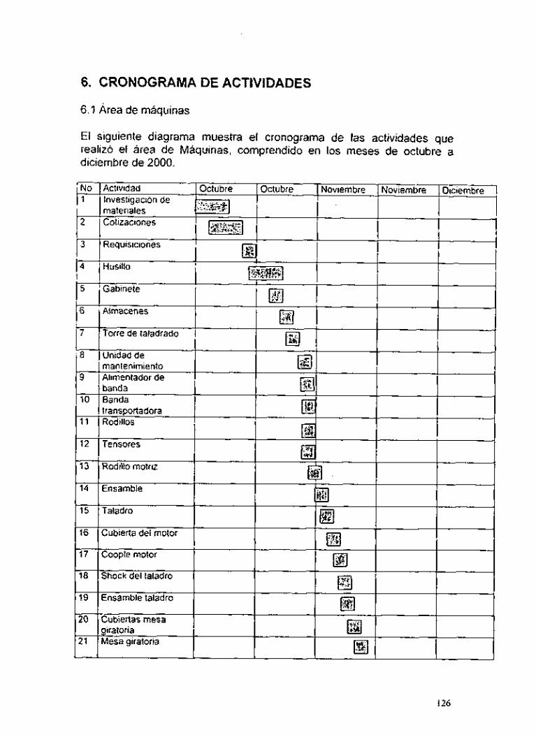
6. CRONOGRAMA DE ACTIVIDADES
6.1 Área de máquinas
El siguiente diagrama muestra el cronograma de las actividades que realizó el área de Máquinas, comprendido en los meses de octubre a diciembre de 2000.
126

No I Aciividad 22 Postes y soportes
23 Cople motor-husillo
6.2 Area de control
Octubre Octubre Noviembre Noviembre Diciembre
El siguiente diagrama muestra el cronograma de las actividades que realizo el área de Control, comprendido en los meses octubre a diciembre de 2000.
~~
5 Circuitos impresos WX L1 : ., (acetatos) , *lt"l Elaboracibn de PCB I
I I ,;nil**
continuidades en pistas 8 I Montajede I I
127
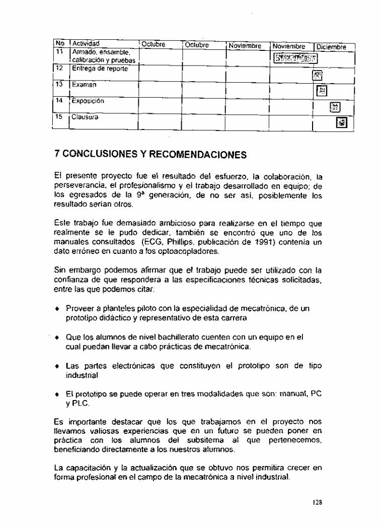
14
15
7 CONCLUSIONES Y RECOMENDACIONES
Exposición
Clausura
El presente proyecto fue el resultado del esfuerzo, la colaboración, la perseverancia. el profesionalismo y el trabajo desarrollado en equipo; de los egresados de la ga generación, de no ser así, posiblemente los resultado serian otros.
Este trabajo fue demasiado ambicioso para realizarse en el tiempo que realmente se le pudo dedicar, también se encontró que uno de los manuales consultados (ECG, Phillips, publicación de 1991) contenía un dato erróneo en cuanto a los optoacopladores.
Sin embargo podemos afirmar que el trabajo puede ser utilizado con la confianza de que responderá a las especificaciones técnicas solicitadas, entre las que podemos citar:
+ Proveer a planteles piloto con la especialidad de mecatrónica, de un prototipo didáctico y representativo de esta carrera
+ Que los alumnos de nivel bachillerato cuenten con un equipo en el cual puedan llevar a cabo prácticas de mecatrónica.
+ Las partes electrónicas que constituyen el prototipo son de tipo industrial
+ El prototipo se puede operar en tres modalidades que son: manual, PC y PLC.
Es importante destacar que los que trabajamos en el proyecto nos llevamos valiosas experiencias que en un futuro se pueden poner en práctica con los alumnos del subsitema al que pertenecemos, beneficiando directamente a los nuestros alumnos.
La capacitación y la actualización que se obtuvo nos permitira crecer en forma profesional en el campo de la mecatrónica a nivel industrial.
128

Es decir, seremos capaces de diseñar, fabricar y dar mantenimiento a equipo y maquinaria automatizada, aplicando conocimientos de las áreas de mecánica y control que incluyan elementos tales como: mecanismos, sensores, actuadores, interfases y controladores.
129
Es decir, seremos capaces de diseñar, fabricar y dar mantenimiento a equipo y maquinaria automatizada, aplicando conocimientos de las áreas de mecánica y control que incluyan elementos tales como: mecanismos, sensores, actuadores, interfases y controladores.
129
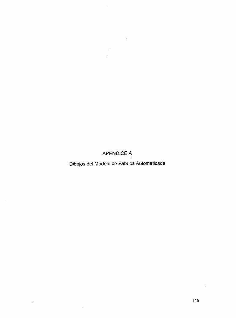
APENDICE A
Dibujos del Modelo de Fábrica Automatizada
130

I
2 I D e d o d e p i n z a I I / S o p r i : 6 : ia p i n i c i
I 1 i r l e I C a n t i d a d h a : 1 5 / 1 2 / 2 0 0 0
: f e r e n c ia: : o { . : mm
E s c . :
i c : t : o I I Enramb le
D e s i g n a c i o n Í M c i : : t o i O b s e r v o : tor,:s CENTRO NACIONAL DE F ~ o y . I r$ J o i i t i ? i i : : o Y ~ T ~ L
D i b . i k g J o r i r i h i r i o V ~ r o i
Rt i L i c A i c o d i o G o r r i e ü:t<ni
- ACTUALIZACION DOCENTE
No. PS P I N Z A S U J E T A D O R b ,

\ \
I z ' a r l e 1 C a n t i d a d ( h a : 1 5 / 1 2 / 2 0 0 0
at.: mm í e r e n c i a :
L s c . :
\ \
a c e r o I p a r t e de la p i n z a s u l e l a d o r a D e s I g n a c I o n M a t e r i a l O b s e r v a ( ¡ o n e s CENTRO NACIONAL DE P r e y . r c r . í r a n t i s í o A r i i l u c ,
ACTUALIZACION DOCENTE D i b . T e r . l i o n i i i i o A r i i r u C.
R t v . 111. A r c o d i o G o r i i o Y c l r h o r
No. P S - D D E D O P I N Z A S U J E T A D O R A
i o * o . 2 c
1 - I
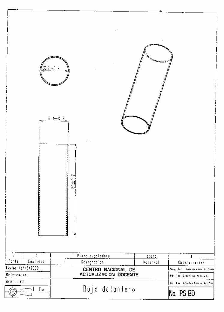
I 1
I I P a r t e j C a n l i d a d
F e c h a 15/12/iOOO R e f e r e n c i a ~
I I
I
P i n z a s u j e i a d o r a a c e r o I D e s i g n a c i o n M a t e r 1 0 1 O b s e r v a c i o n e i CENTRO NACIONAL DE P ~ O ! IU r r o n r i i i o c o r
ACTUALIZACION DOCENTE D i b l r r I r o n c i s c o A r i i i u C
Rti. hi. A r c o d i o 6a:c io Y c l i h c A t o l . : mm
No. PS-BD E r c . : B u j e d e l a n t e r o

6 '\ 7.. I I '.. --__- -e-
I 2 a i l e I C a n l i d a d : h a : 1 5 / 1 2 / 2 0 0 0
) I . : mm i e r e n c i a :
E s c . :
P i n z a s u l e l a d o r a a c e r o l D e s i g n a c i o n M a l e r i a l O b s e r v a c i o n e s
P r o l . Ing J o i i c r R i i e r o Y i i o s
D i b l o g . J o r i r r h i r r o V I I P I
A r i . hl. A r < e d i o G o r o o W c h o ,
CENTRO NACIONAL DE ACTUALIZACION DOCENTE
No. PC-BC B u J e s e c u n d a r i o
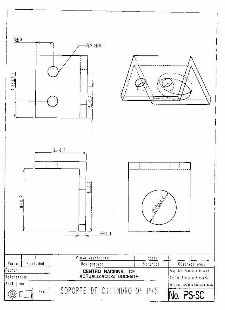
5 i o . I
I I P i o s a s u j e l a d o r a o t e r o
I
I
I 4 I
i-- I -0 !
( h a : f e r e n t i o :
CENTRO NACIONAL DE h o y . T e c . i i O " < i , < O A I , , , " c . ACTUALIZACION DOCENTE D i b . l c c i r o n t i i i o A r i i r u C.
S O P O R T E D E C l l l N D R O D E P I S N ~ , ps.sc E st

~
I 2 P i n l a s u j e t a d o r a a t e r o I P a r t e 1 C a n t i d a d D e s i g n a ( i o n M a l e r ial O b s e r v a ( ¡ o n e s
' F e c h a : 1511212000 CENTRO NACIONAL DE P r a y . l e c . F r e a c i i r o A r i i i u C o n
R e í e r e n c i a : ACTUALIZACION DOCENTE D i b . i t ( . i r o n t i s c o A r i i r u C. . .
I
A t o t . : mm R r i . L i c . A r ( o d i o G o r t i o U t l ( h o a 0 - E S ( . : B r a z o d e P i n z a S u j e t a d o r a No, ps_B

\,
e c h a : CENTRO NACIONAL DE P r O y . I t ( . ~ I Q n l i S l Q A r i i l u c . e f e r e n c i a : ACTUALIZACION DOCENTE D i b . l t c . I ~ O K ~ X Q A r i i i u C.
, c o i . : mm RIi. L i l . A r l Q d i Q G Q r t i O H t l l h o
NO. PS-PA E s t . : 3 P E R N O A P O Y O
I 2 P i o s a s u l e t a d o r a a c e r o I

I1
I I P i n s a s u l e l a d o r a
I -I
o t e r o I
jli 3 + . o . o 1 iip- 2 k t o . 2 I _1
‘ a r t e I C a n t i d a d 1 D e s i g n a c i o n M a t e r i a l
< 7 r t 0 . 2
O b s e r v a c i o n e s
~ ~ 7 . 4 2 f 0 . 2
t h o :
f e r e n t i a :
4fO. I
CENTRO NACIONAL DE ~ r b ~ . i t < , r r e n < i r r o c ,
ACTUALIZACION DOCENTE D k b . l r c i r o a c i x o ~ r i i i v C.
ir.---
?
SOPORTE D E P I N Z A S U J E T A D O R A N ~ , ps-s Est I
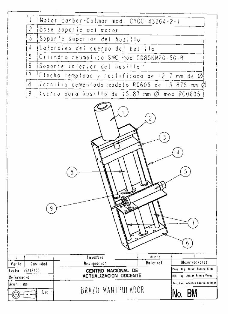
I Motor B a r b e r - C o l m a n m o d . C Y Q C - 4 3 2 6 4 - 2 - 1 2 B c s e s o p o r t e d e l m o t 0 . r
3 S o p o r t e s u p e r i o r d e l h u s i l l o 4 L a t e r a l e s d e l c u e r p o de.1 h u s i l l o 5 C i l i n d r o n e u m o t i c o SMC m o d CD85KN20-50-8 6 S o p o r t e i n f e r i o r d e l h u s i l l o .
8 T o r n i l l o c e m e n t a d o m o d e l o R0605 d e 1 5 . 8 7 5 mm $3 3 I u e r c a p a r a h u s i l l o de 1 5 . 8 7 mm @ m o d R C 0 6 0 5
-
__ 7~
-
E n samb I e A c e r o I I P a r t e 1 Cantidad D e s i g n a t i o n Mater ¡ a l
e c h a : 1 5 / 1 2 1 0 0 CENTRO NACIONAL DE e í e r e n t i o : ACTUALIZACION DOCENTE
r n l ' mm
I O b s e r v a c i o n e s
P r e y . l o g . J o i i r r R i t t 1 0 V i r a l
D i b . l i s . J a v i e r Riiiro Y i i o l
R c r . L i < . A r < o d i o Gar(io Y t l l h o ." , 1 1 1
E S ( No. BM B R A Z O M A N I PULADOR

5 5 4 7 . 5
I 2
1 2 . 5 -
B r a z o m a n i p u l a d o r A c e r o I
-0
-0
P a r t e I C a n t i d a d I D e s i g n a c i o n
O
M a t e r ial O b s e r v a c i o n e s
6 5 0
d
O 0 I
1 A T E R A l E S D E L H U S I i t 0
A c o t mm
E S [
/6 d4
R e i L i c A r c a d i o G n r t i o W i l c k o
NO. BM- LH
c
3 5 0
I -I L 2 5
-2
l i e c i a : 1 5 / 1 ? / 0 0 1 R e f e r e n c i a :
CENTRO NACIONAL DE ACTUALiZACiON DOCENTE

i I
I I
2 6
1I
Br ai0 man I p u I a d o r A t r r a I I
f e c h a : 1 5 / 1 2 / 0 0 R e í e r e n c io:
CENTRO NACIONAL DE P r a y . I n q J o i i r r R i i < : a V i i a i
ACTUALIZACION DOCENTE D i b . I n q . J o i i t r R i i r i o V i i ~ i
0 - S O P O R T E SUPERIOR D E L HUSlliO -1

20 I /
I
I 25
/ \
O
I B r a i o man I p u I a d o r A c e r o I P a r l e I C a n i i d a d
F e c h a : 1 5 / 1 2 / 0 0 R e i e r e n c ¡ a : A c o l . : mrn
E S ( . :
D e s i g n a c i o n M a t e r ¡al O b s e r v a c i o n e s P r e y . Ing. J o r i t r R i r r r o V i i m CENTRO NACIONAL DE
ACTUALIZACION DOCENTE D i b . I n g . J o i i t r R i v e r a V i i a i
R e v . L i < . A r c a d i o G o r t i o Y i l l h o
S O P O R T E M E D I O D E L H U S I L L O N~~ BM-SMH

#7
- 2
I I B r a r o m a n i p u l a d o r A c e r o
@ 1 2 .
I
-
7
' a r t e 1 C a n t i d a d I D e s i g n a c i o n M a t e r i a l O b s e r v a t ( o n e s ( h a : 15112100 f e r e n c i a :
Pro).. Ing. J o i i t r A ~ I ~ I P V i i o , CENTRO NACIONAL DE ACTUALIZACION DOCENTE D i b . I n g . Joiirr R i i r r o V i v o s
-1 SOPORTE I N F E R I O R D E L H U S l l l O

#28.58 2 T 50 .h
2 # 4 . 7 6
I I ' a r l e I C a n t i d a d c h a : 1 5 / 1 2 / 0 0
0 1 . : mm f e r e n c i a :
E r c . :
f ir a z o m a n i p u l a d o r A c e r o I D e s i g n a c i o n M a t e r i a l O b s e r v o c i o n e s CENTRO NACIONAL DE Pro!. T U r r a n l i r < p
ACTUALIZACION DOCENTE D i b . i t [ . í r o n i i i i o A r i i r u
R e t . L i c . A r c o d i o G o r l i o üt18 B A S E D E L MOTOR D E L H U S l l l O NO. BM-BMt

I 2 3 4
E a s e d e l a u n i d a d d e m a n t e n i m i e n t o T o r r e d e l a u n i d a d d e m a n f e n i r n i e n t o S o p o r t e d e l a u n i d a d d e m a n t e n i m i e n t o F i l i r o r e g u l a d o r S M C m o d A W 2 0 0 0 - 0 2
! I P a r t e 1 C a n l i d a d : ( h a : i J / i ~ / O O t i e r e n c i a : : o l . : mm
E s c . :
E n somb I e A c e r o I D e s i g n a c i o n M a t e r i a l O b s e r v a ( i o n e s CENTRO NACIONAL DE Proy. Inq. J o t ~ c r R i i c i o V i r a s
ACTUALIZACION DOCENTE Dib. ln q . J o i i t r A i w o V i r a r
Air. L i c . A r c a d i o G o r t i o Y c l c h o r
U N I D A D DE M A N T E N I M I E N T O N ~ , UM

10
I a r l e I C a n t i d a d r h o : 1 5 / 1 2 / 0 0 í e r e n c i a : 3 1 . : mm
I
4
U n i d a d d e m a n t e n i m i e n t o A t e r o I D e s i g n o ( i o n M a t e r i a l O b s e r v a c i o n e s CENTRO NACIONAL DE h o y . I n q . J o r t c i R I I ~ I P V i v o s
ACTUALIZACION DOCENTE D i b . I n q . J o i i r r R i i r r o Y , ? o s
R e i . L i i . A r i o d i o G ~ r i i u M e l i h o i
O
B A S E D E 1A U N I D A D D E M A N T E N I M I E N T O
E s c . :
o-
NO. UM-B
r /
O
H T I O
4 m
+
35

350
I
- 40
L
r

R20 -, I
2 # 6 . 3 5 7
I 2 5

- - / ¿ j L a r a l c t e r a l f r o n t a l d e l a b a n d a -. I -
4 5 6 7 8 9
13 I K o d i I l o l o c o M o t o r B a r b e r - C o l m a n m o d e l o C Y Q C - 4 3 2 6 4 - 2 - C a j a d e l b a l e r o S e p a r a d o r d e b a n d a R o d i l l o m o t r i z R o d i l l o i n d u c i d o B a n d a d e p o l i u r e t a n o m o d l M 6 U O - U 2
4
I I P a r l e I C a n l i d a d
F e c h a : 1 5 / 1 2 / 0 0 R e f e r e n c i a : A t o l . : mm
A c e r o I E n s a m b l e d e la b a n d a D e s i g n a t i o n M a l e r io1 O b s e r v a ( i o n e s CENTRO NACIONAL DE P r e y . l n g . J o i i t r R i i r r o V l r o r
ACTUALIZACION DOCENTE D i b . Ing. J o r i t r R i r i r o V i v o s
R r i . L i c . A i ( o d i o Goriio Yelihor
E s c . : B A N D A T R A N S P O R T A D O R A No. BT
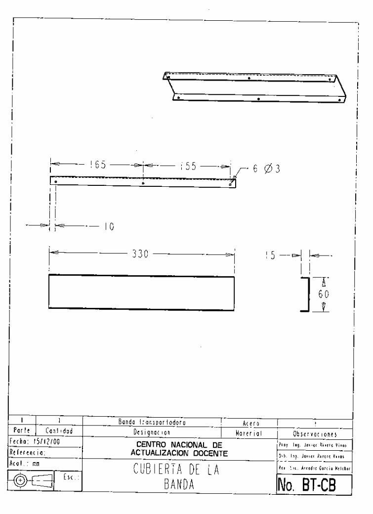
3 3 0 ---7 l 5 -7
I I i r l e 1 C a n t i d a d h a : 1 5 / 1 2 / 0 0
' e r e n c io: i f . : mm
I,
B a n d a t r a n s p o r t a d o r a A c e r o I D e s i g n a c i o n M a t e r i a l O b s e r v a c i o n e s CENTRO NACIONAL DE P r e y . Inq. J e y i t r R i i e r e Viios
ACTUALIZACION DOCENTE D i b . l a g . J o i i r r R i i c i r i Yiror
C U B I E R T A D E L A B A N D A E s c . :
Rrr L i c . A r t a d i o h l i 0 Y c l r h o r
NO. BT-CB

I

‘“k
I I a r l e 1 C a n l i d a d t h o : 1 5 / 1 2 / 0 0 í e r e n c i a : a l . : mm
E s c . :
r e i 2 2
I B a n d a l r a n s p o r t a d o r a A c e r o I D e s i g n a c i o n M a t e r i a l O b s e r v a t i o n e s CENTRO NACIONAL DE ?tag. Ing. J o v i i r R t i c r a V i i o !
ACTUALIZACION DOCENTE D i b . I n g . J o r i r r A 8 i t r a V i i a i
R t r . L i i . A r c o d i o Gotti0 Utlchoi
NO, BT-RM ROD I110 M O T R I Z

g4.76
I I P a r l e I C a n l i d a d e c h a : 1 5 / 1 2 / 0 0 e l e r e n c i a : c o t . : mm
E s c . :
r 6.35
B a n d a t r a n s p o r t a d o r o A c e r o I D e s i g n a c i o n M a t e r i a l O b s e r v o c iones CENTRO NACIONAL DE P i a l . ing. h i i t ! h i r i a V ~ V P S
ACTUALIZACION DOCENTE Oib. I n g . J P V I ~ I R i i r r o V i i e i
A c r . L i t A r i o d i o G a r u a üt l<h i
NO. BT-RL RODlllO LOCO
I 60

_[ I
I
I I
I 4 ‘ a r t e I C a n t i d a d ( h a : 15/12/00 f e r e n c ia: 0 1 . : mm
I B a n d a l r a n l p o r t a d o r a A c e r o I
D e s i g n a c ion M a l e r ¡ a l O b s e r v a c ¡ o n e s CENTRO NACIONAL DE P r o l . l o g . J a v i e r A i i t ro V ~ V D ,
ACTUALIZACION DOCENTE n i b . I n p . J o i i t r R i i t r o V i i o i
R e t . L i c . A i i o d i o G O ~ C ~ O W t l i h o
60
1 I 0 _I--
76
R2
4
38
16

i
I 4 ' a r t e I C a n t i d a d ( h a : 15112100 f e r e n c i a :
60 4 7 . 3
B a n d a I r a n J p o r l a d o r a A c e r o I D e s i gnac i o n M a l e r i o / O b s e r v a ( i o n e r CENTRO NACIONAL DE Pro!. l a g . J o i i c r R I I C I P V i v o s
ACTUALIZACION DOCENTE D i b . I n o . J o i i c r R i i i r o V i v o s
76
o f mm
t S C
4
Rei L t ( A r i o d i o G o r i i o k l r h o
NO. BT-SB S E P A R A D O R D E B A N D A
r, 35

F - - - - 4 5 - - - - - - - 4 1"
I I a r t e I C a n t i d a d ( h a 1 5 / 1 2 / 0 0 f e r e n c i a
L
B a n d a T r a n J p o r i a d o r a A c e r o I D e s i g n a c i o n M a t e r i a l O b s e r v a ( i o n e s CENTRO NACIONAL DE P r o y I n g J o i i c r R i r r r a V i v o ,
ACTUALIZACION DOCENTE D i b lng J o i i i i R i i r r o V i i o r
I 22.5-4 I
0 1 . : mm
E s c . :
@ 1 5 . 8 6 + , 0 0 4 r
R e i . 111. ) \ l l O d l P G o r l i o Y t l t h o
NO. BT-CB C A J A D E L B A L E R O
- 4 . 4
r R 2
I L
r 6 . 5
25 I
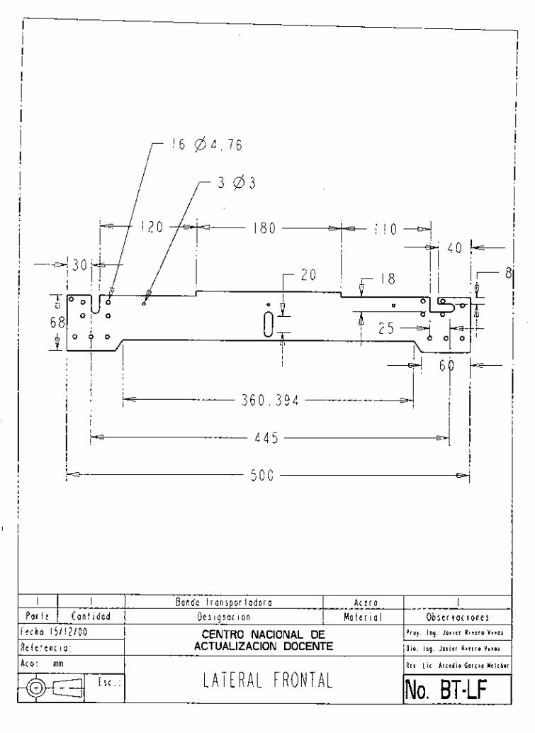
4 3 0
I I ' a r l e I C a n t i d a d i t h a : 1 5 / 1 ? / 0 0 i í e r e n c i a .
c 445 Lz=
B a n d a t r a n s p o r t a d o r a A c e r o I D e s i g n a c i o n M a t e r i a l O b s e r v a ( ¡ o n e s CENTRO NACIONAL DE P r o y . Ing. J o i i r r R i r t r o Vire,
ACTUALIZACION DOCENTE Oib. l s o . J o i i t r A i i e r o V i i m
- - 500 v /
o t rnrn
E s c R t i hi A r t a d i o G o r o o W i b e i
NO. BT-IF L A T E R A L F R O N T A L

R
I
1 4 0 4 . 7 6 r--
I E o n d o i r a n s D o r t a d o r 0 A c e r o I P o r l e I C a n t i d a d
F e c h a : 1511212000 R e f e r e n c i a : A c o t . : mrn
E s c . :
L- 500 L=
D e s i q n a c i o n I . M a t e r i a l O b s e r v a c i o n e s CENTRO NACIONAL DE P r a r . Ing. J a i i c r R i i c r o V i ras
ACTUALIZACION DOCENTE Dib . lng. j o ~ i t r R i i r r o V i i o r
R t i . L i c . A i r o d i o G o r t i o Yclihor
NO. BT-LP L A T E R A L P O S T E R I O R
T 6 8
3-

I t I M o t o r e l e c t r i c o B a r b e r - C o l m o n n -
I L
3 4 5
I
i -1
- P o s t e s M e s a c i r c u l a r g i r a t o r i o S o p o r t e m o t o r y p o s i e s
S o p o r t e c o p l e m o t o r - m e s a c i r c u l a r
A
I I P a r k 1 C a n t i d a d
F e c h a : 1 5 / 1 2 / 0 0 R e f e r e n c i o : A t o t . : mm
E n s a m b l e I A : e r o I D e s i g n a c i on M a l e r i a l Observa( i o n e s
CENTRO NACIONAL DE P r o l . Ing. 1 c i i c r R i i l r o Y i i P ,
ACTUALIZACION DOCENTE D i b . I n g . J o i i c r R i i c r a V i ra>
R t i . l i r A r t o d i o 6 o r t 1 o Y r l c h o i -1 0 - M E S A C I R C U L A R G I R A T O R I A

n
I 4 M e s a q i r a l o r i a A c e r o P a r t e 1 C a n t i d a d D e s i g n a c i o n M a t e r i a l
F e ( h a : 151 1 2 / 0 0 CENTRO NACIONAL DE R e í e r e n c i o : ACTUALIZACION DOCENTE
A c o t . : mm
\ V
I O b s e r v a c ¡ o n e s
P r o y . Ing. Jo i i r r A i i ( r a Vi105
Q \ b . I n g . J a v i e r Ri i r ro V i i o ,
Rti. L i c . A r c a d i a G a r c i a Yelcha
6 . 3
P O S T E S INo. MG-P

r
I 1 E s t r u c t u r a 2 / C i I i n d r o SMC CD85KN25-80 3 4
I 5 I C u e r B o - m o t o r I
~
C i l i n d r o S M C C J 2 B I O - 3 O S B a s e d e l a t o r r e
16 I S o p o r t e c i I i n d r o I
I I E n s o m b l e A c e r o P a r t e I C a n t t a a d D e s i g n a c i o n M a t e r i o / e c h a : 1511212000 CENTRO NACIONAL DE e f e r e n c t o : c o l . : mm
ACTUALIZACION DOCENTE
E s c . : T O R R E D E T A L A D R A D O
1 7 I S o p o r t e p i e z a I
I O b s e r v a c i o n e s
P r p y . l a g . J a v i e r R i i r r a V i v o s
D i b . l a g . J o r i i r Aircro V i i P l
U t i . l i i . A r i o d i o G a r < i o Y i l i h i
No. TT
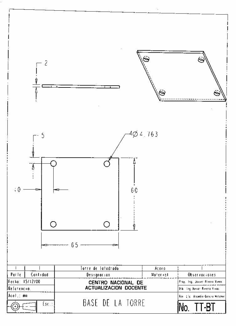
1, , ,
T 1
I
60
I T o r r e de t a l a d r a d o A t e r o I P a r t e I C a n t i d a d
F e t h a : 1 5 / 1 2 / 0 0 R e f e r e n t i o : A t o t . : rnm
B A S E D E I A T O R R E
D e s i g n o t t o n M a t e r i o 1 O b s e r v a ( i o n e s P r a y . I n g . J o i i r r R i i r r a V i r o !
Dib . I n g I o t i t i R i i t i o V i r o i
I R t i . L i c . A r c a d i o G o i c ! o Y t l c l
CENTRO NACIONAL DE ACTUALIZACION DOCENTE
INo. TT-BT
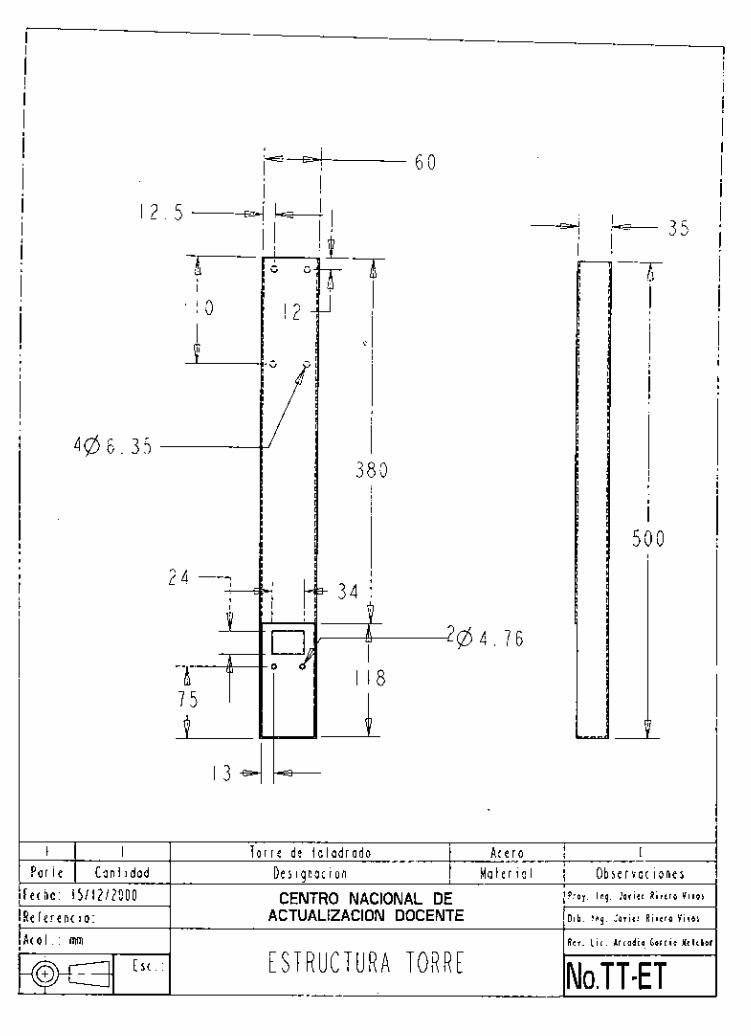
380
I
I I 8
I T o r r e de t a l a d r a d o A c e r o I
50 O
A t o l . : mm
E S ( . : i ST R U C T U R A TORR E R e v . L i c . Arcad ia . b a r c i a Y i l ( h o
NO. T T - E T
/ F e c h a : 1 5 1 1 2 1 2 0 0 0 I R e f e r e n c i o :
CENTRO NACIONAL DE ACTUALIZACION DOCENTE

e r 4
I I T o r r e d e t a l a d r a d o A c e r o I P a r t e I C a n t i d a d e c h a : 1 5 / 1 2 / 0 0 e i e r e n c i a : ( a t . : mm
E s c . :
D e s i g n a c i o n M a t e r ¡ a / O b s e r v a c i o n e s CENTRO NACIONAL DE P r o y . Ing. J o i i c r R i i r r o V i i o i
ACTUALIZACION DOCENTE Dib. I n g . J o i i r r R i r c r o V i i o r
R e i . L i c . A r c a d i o G o r r i o M e l i b C U E R P O C A M I S A D E t MOTOR No.TT-CCM

I I E n s a m b I e A c e r o 1 P a r t e I C a n t i d a d : t h o 151121GG : l e i e n c i a
D e s i g n a c i o n Moler i o 1 O b s e r v a ( i o n e s P i o y I n g J a v i r r R i r r r o V i r o i CENTRO NACIONAL DE
ACTUALIZACION DOCENTE D i b I n q J o i i t i R i i r r o V i r o $
0 1 mm
E r c R c r L i r A r c o d i c G o r c i o Y r I r h o
A L I M E N T A D O R D E 1A B A N D A N ~ . AB

A 5 0 1 0 . 3
I I ' a r l e 1 C a n t i d a d : t h o : 1 5 / 1 2 / 0 0 ' f e r e n t i o : O/'. : mm
E s c . :
A I i r n e n t a d o r de b a n d a A c e r o I D e s i g n a c i o n M a t e r i a l O b s e r v a c i o n e s CENTRO NACIONAL DE P r o l . T i c . i r o n c i s r e A r i i i u Coni
ACTUALIZACION DOCENTE O i b . l t c . I r o n c i s t o A r r i i u C o n d i
Rt i . L i c . A r c a d i o torrio Y t i i h o i S O P O R T E D E P I E Z A A A L I M E N T A R NO. AB-SP

4
I
l O i 0 2
-1
I A I i m e n l a d o r d e B a n d a A c e r o I ' o r i e l C a n l i d a d I D e s i a n a c i o n M a t e r i a l O b s e r v a c i o n e s
0 1 . : mm
t h o : CENTRO NACIONAL DE f e r e n c io: ACTUALIZACION DOCENTE
E s c . :
P r o y . Ing. J o i i t r R i v e r a V i i o i
D i b . Ir ig. Jorirr A i i c i o V i r a s
B A S E D E L C l l l N D R O A L I M E N T A D O R D E B A N D A INo. AB-BC

! I
I -4.- A I i m e n l a d o r d e B a n d a
1 0 * 0 . ? , 1
A c e r o I P o r t e I C a n t i d a d : ( h a : 1 5 / 1 2 / 0 0 ? f e r e n c i a .
o M i
Des i g n a c i o n M o l e r ¡ a l O b s e r v a ( ¡ o n e s
CENTRO NACIONAL DE P r e y . I r c . f r a n í i i c o A i r i i u C o n ,
ACTUALIZACION DOCENTE [ l i b . l e í . i r o n t i i i o A r r i r u C o a d
I I
E s c NO. AB-AP A L I N E A D O R D E P I E Z A : o t . : mm I I R r i . L i c . A r i o d i o G o r i i o Y t l í h a

- I N i v e l d e a l m a c e n 2 B a s e d e a l m a c e n .
13 / E s t r u c t u r a d e a i m a c e 1
I 2 a r l e I C a n t i d a d t h o 1 5 / 1 2 / 0 0 f e r e n c i o
o 1 m m
3 -
Ensamb I e A c e r o I D e s i g n a c i o n M a l e r i a l O b s e r v a c i o n e s CENTRO NACIONAL DE P r o 7 lng J o i i r r R t i r r a V i i a s
ACTUALIZACION DOCENTE O i b Ing J o r l t r A i i t r o V i i o r
R e i L t 1 A r i o d i o G a r c i a Y r l < h i A L M A C E N E S D E M A T E R I A P R I M A Y P R O D . T E R M NO, A-MP-PT
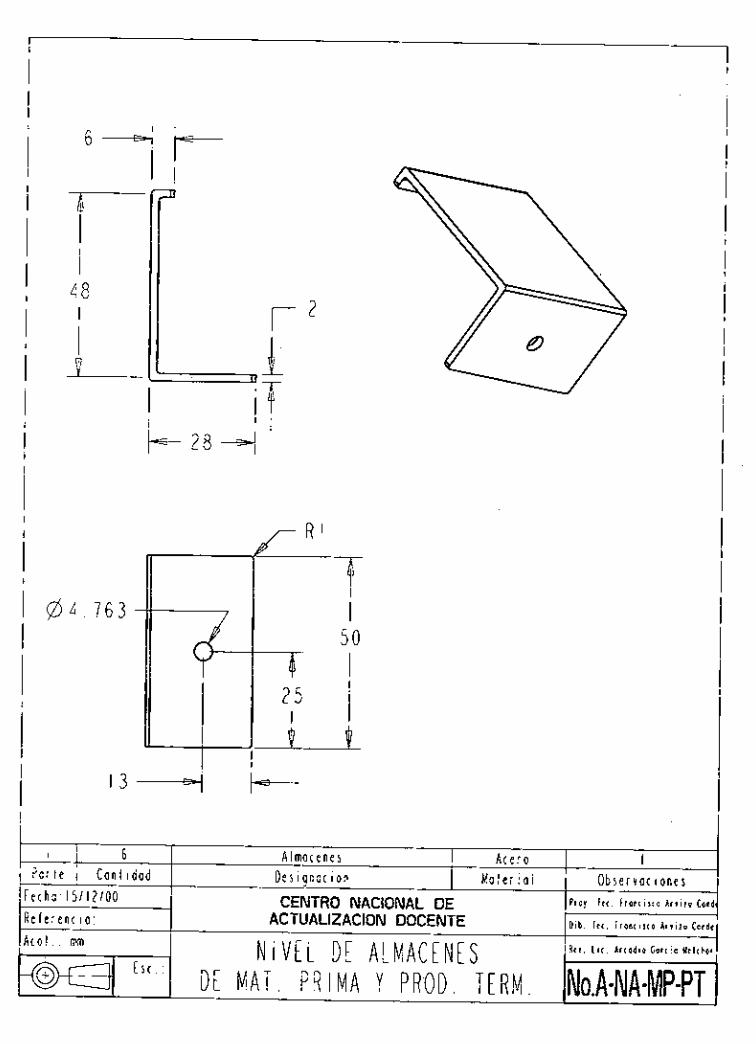
@4. 7 6 3
I
I D
6
r2
o r l e 1 C a n l i d a d t h o 1 5 / 1 2 / 0 0
A I ma( e n e s A c e r o I M a t e r i a l O b r e i v a c i a n e s D e s i g n a c i o n
CENTRO NACIONAL DE P l o y I C < i r o n t i i i o A r i i i u C o n i
f e r e n c i a o f mm
3 - "(
ACTUALIZACION DOCENTE D i b l e c i r o n r i i i o A r i i l u C o n d i
Rti L i < A r t o d i o G o r r t o U t l i k o i N I V E L D E A L M A C E N E S D E M A T . P R I M A Y P R O D . T E R M . No.A-NA-MP-PT

m
/ 4@4 76
I 48
2 I P a r l e I C a n t i d a d e c h o : I 5 / 12/00 e f e r e n c i a : [al.: mm
L
A l m a t e n e s 1 . A c e r o I D e s i g n a t i o n M a t e r i o / O b s e r v a c ¡ o n e s CENTRO NACIONAL DE P i o r i t t r r a n i i , ~ e ~ r ~ ~ i ~ c .
ACTUALIZACION DOCENTE D i b T r r . i r o n r i r r o A r r i r u C o n d
R t r . h i . A r t a d i o úor ( io Y t l i h e

4
6 I a í l e 1 C a n t i d a d ( h a : 1 5 / 1 2 / 2 0 0 0 i e r e n t i o : o t . : mm
E s c . :
1 6 3
A Imat e n e I A t e r o I D e s i g n a t i o n M a t e r ¡ a l O b s e r v a c i o n e s CENTRO NACIONAL DE P i n y . r e i . f r o a r i x o L r i i r u Coa
Dib. I t < . f r o n t i s l o A r v i r u Condm
R e y . L i t . A r t e d i o C o r t i n Y t l t h o ~
ACTUALIZACION DOCENTE
S U J E T A D O R D E N I V E L D E L A L M A C E N E S NO. A-SA

APÉNDICE B
DATOS TÉCNICOS
131
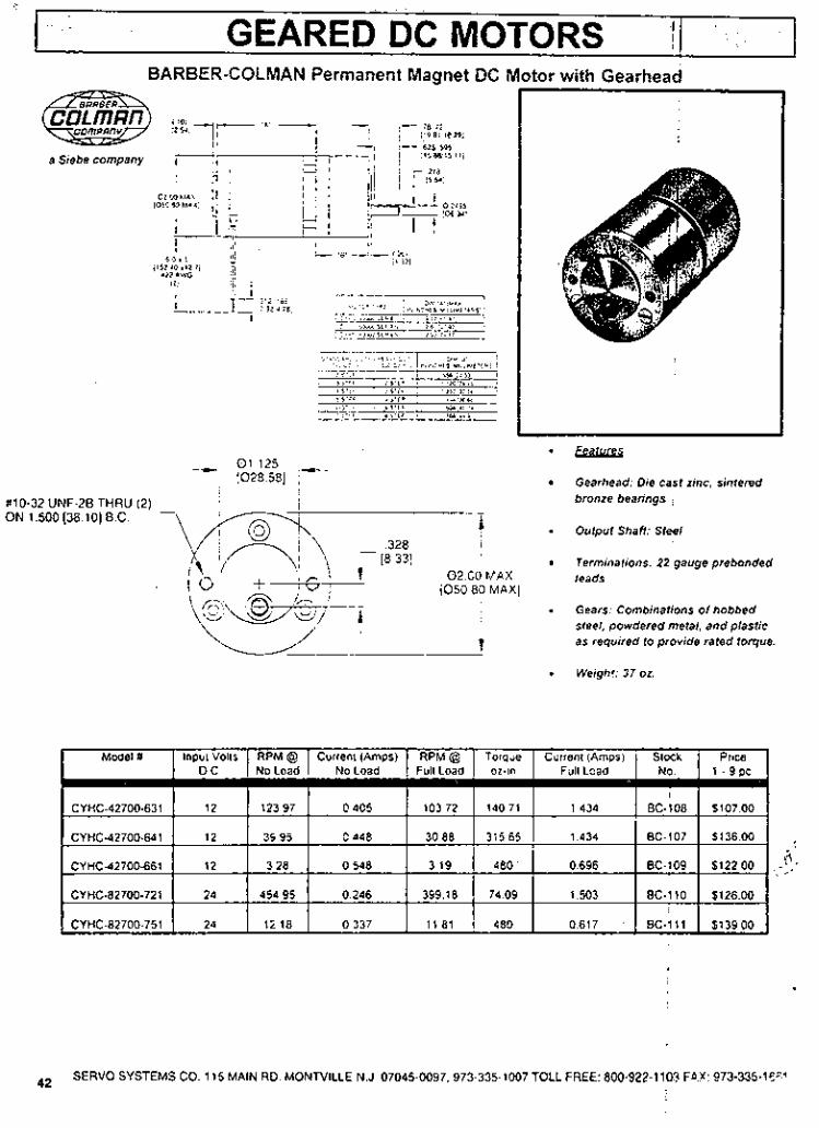
GEARED DC MOTORS l j I
BARBER-COLMAN Permanent Magnet DC
a Sebe company
O1 125 ,- -- 1028581 ,
#lo-32 UNF-28 THRU 121 ~ . . I I I
328 (8 331
- ON 1.500 [38.10] B.C
'tor with Gearhead
-¡%.lLas
Gearhead: Die casi zinc, siniered bronze bearings
- Ouipul Shaíi: Steel
Terminaiions: 22 gauge prebonded 0 2 O0 MAX leads [O50 80 MAXI - Gears: Combinations of hobbed
sieei, powdered meial, and plastic as required io provide rated toque I . Weigh!: 37 oz.
~. \4; '~ /
CYHC-82700-751
SERVO SYSTEMS CO. 115 MAIN RD. MONrViLLE N.J. 07045-0097.973-335-1007 TOLL FREE: 800-922-1 103 F W 073-335-19' 42

. . , , .,.. '..... I x.: ':..?<.;;< ::,>;,c.;: .. . .,. , 'c.c.. PERMANENT MAGNET DC GEARED MOTOR$ . , .
BARBER COLMAN GEARED DC MOTOR Model #CYíiC-23604-39
Uiss Rated for 32VDC. 44ma.. 24RPM NO Load
Lab Test @ 24VDC
BeM_ iLlBa 20 ,043A. N.L. 16 1 .OA. 6002-in 10 2.OA. 12502.in
Dimensions: Body: 2" dia. x 3-114' L.. Pilot: 1-118" d1a.x 1/16., Face Mount: 121 tapped holes Shaft: 0 .250 dia. x 7116" L. wi lh flat.
Stock No. DM-628. . . . .C17.50
110.321 on 1-112" dia. B.C.
GLOBE 3A1548 DC Motor with Precision Clutched Dual Speed Gearhead. Specs. 24VDC input on molor & clutch. Hiah SLmed, 24VDC. 85ma.. 230 RPM wiih ciutch 1de.energizedl LOW soeed. 24VOC. 85ma.. 15 RPM With c'lulch lenergizedl Lab Test: Hmh soeed. 24VDC. 550ma 150 RPM wiíh 6ó oz:in load applied LO^ speed. 24VDC. 190ma.. 15 RPM with 120-1 +I or-in applied Dimensions: Body 1.112' dia. x 6.114'L.. Pilot 1. l l i "dia. x 314-L.. Flange Mt. 2' Sq. x 118' wl 4 holes on 1.112" cenlers. Shal1:O.ZSO' x 314. L RUE Stock No. DM-505 . . . . .S79.0(
UHLER GEARED D.C. MOTOR IODEL #127P91172
. Rated for 24VDC. 370 RPM, 90 ma. No Load Lab Test, 280 RPM. 400 ma. @ 21.2 or.-in. torque, stalled @ 60.0 oz..in., 1 Amp.
l5mmQnz Jdy: 1.38" dia. x 2.5" L. haft Offsei: 0.194" dia. x 0.630 L. ,ith flat, connection via 20" leads. lounting 131 tapped 4-40 holes O n facr tock No. DM-639. . . . .$16.0
-
- arber-Colman ¡eared DC Motor lodel# CYClC-43264-2-1
iated For: 24VDC @ 80rne. lo load speed: 58 RPM ab Test: &id speed cuImni
60 01-in. 40 RPM 470 ma. '20 02-in. 25 RPM 900 ma. ,e0 oz-in. 9 RPM 1.3 Amp
Jimensrons: M y : 2' did. x 3.7.L. Fan, Mounf wilh (2 apped holes 10-32 lhd. on 1.5'8.c. ;han: Oilset. 0.250'dia wilh Ilal x '1/16"L Stock NO. DM.654 . . . .C28.5
I
iRBER-COLMAN r'QC43204-46 Gearhead DC otor. jecs.
24 VDC, 75ma.. 40 RPM no load. Max. Load 150 oz-in. Speed @ mex. load 32 RPM Currenf @ max. load 375ma. . .
l.xzLWs dy 2" dia. x 3.114"ii. Pilot 1.118" L. x 1/16", face mt.,:(21 tapped les110-321. on 1.112" dia. BC. Shaft: 'set ,250'' dia. x 7/16"L. ock No. D M - 4 9 2 . . . . 517.50
j
;
ARBER-COLMAN Geared PM IC Motor ~
lodel #FYOF63410-32
.
. Conlinuous io& rating: 34 odn. , imensions: 1.38" dla. x 2-518" L. ace mount 131 4-40, holes, shatt offset '' ,1875" x 3 4 " L.
,dock No. DM-576 . . . .$15.6Q
Rafed for 24 VDC., 250 RPM, 120 ma. no load
SERVO SYSTEMS CO. 11 5 MAIN RD. MONTVILLE N.J. 07045-0097.973-335-1007 TOCL FREE. nn0-922-1103 FAX: 973-335-1661 44

BAN DAS TRANSPORTADOR,
&IEMebe:
alarga. miento
ESPEClFlCA,ClON DEL CODICO
Interposicion eventual
imdicada solosi es dilerenle
i I I
Materiales de cobertura y de interposlcion
M Rigida
T Flexible
MT Mixta
FG Fibra de vidrio
U Poliureiano
V Cloruro de polivinilo (PVC)
G Eiasiomero
S Sii:cona
PF Poiioiefina
Abreviaciones no contempla@ en el codiw: LF Superficie con bajo coeficiente de lriccion MF Superficie con medio coeficiente de friccion
N 8 Las bandas CHIORINO rienen una eslruclura rexrii de polieslei Hacen excepcioii las bandas SILON, las bandas elaslicas y las bandas con rlvcleo de rracclon de poiiamida Para eslos iipos no vale esfa llave de inlerprelaclon
.. . <_.I üt+s . ~~ características . I . . ..., . - j A Ant estatico I nd caoo 50.0
en caso ae nomon m a con I d a Danza s n an~esid'co, I
FR Flame reiaidanl: anliilama I HF Su erticie c n elevado
co8iciente $e friccion indicado solo eo caso de b omonrmia con bandas
L F y MF,
iñ ioior transparente I r lana f81-k iirnentaoa
FI FM FH . _
GP GPL LG
!
, ... , . 1 ..is ,'>.A ..-. ""I
PN

1 METODOS DE EMPALME I I
Los iipos de empalme descritos a coniinuación lian sido esiudiados 1pdr.i cutii/Jlir coli los requisiios qur pueden encoiiirxse en niultiples alilicacioner. Están direciarnenie relacionados con el iipo de banda elesida ai ¡ cnnio con las condicionrs de iia/i,iio.
* Empalmes EN ZETA fí$. 1. 2. 3. 41: asewraii la i i iár irna ilexil)ilidad v rc:ularidad en tod,i Id zona de enipalnie.
* Empalmes SOBREPUESTOS iii,e. 2. hi : especiiicor l),irii ulios iipos de Iiaiidd s' de .iplicacióri mnin ,diriii,itii ,i '1 los i,ié:oclos i:,itlicion,des P n h l i l r Y iri1)le zeia.
Empalmes MECANICOS : se emplean cuando re rrquiere rapidez en nioiiiar vrlesniontar la banda o liien cuando h a y diiicultad rii efectuar i
el empalme solire insidlación. Pueden ser GRAPAS METALICAS Ng. i. 81:
.- Tipo ,il/8\i w ~ m i , i ,i!i:o ~ i , i r ~ i I h w h rlc riíis D ;xi? I ,ip,~.>, \ n ticcw;,i crl~iiliiii iyc>ci,ilc. 1i,irc! i i i i l i l ic.ici i in I / DE PLSTICO. < I . (*:w+,in en IT . , ( ! r : rc: fw' d i , :iic!;,il" > cii Li 1 1 i (
Tipo hi/G: i i r ic i i ia ,iliiii para Irida c!&e de lwnrl,is. Secesii,i eqiiipiic r'!ii,ciales liara su aplicacinn
EMPALMES EN ZETA
Fjg 1 .MICRO ZETA Fig 2. ZETA SIMPLE
EMPALMES SOBREPUESTOS
Fig 5 BISEL Fig 6 - TRIPLE BISEL - P
COEFICIENTE DE FRlCClON LADO DESLIZAMIENTO ~~ ~
Chapa lest Tambor Tambor oma$era ' 1 acero 1 lorrado I I 0.UO 1 , 0.20
0.25 , 1 I( I 0:;: 1 so 0.30 0.40 0.30 0.50
u3. u5 0.60 0.50 0.60
V5, V10. PF5 no dolicable 0.60
TOLERANCIAS PM~'BANDAS SIN FIN \TRAMOS
y_-
F:g 3 -DOBLE ZETA Fig 4 - TRIPLE ZETA
E M P A L M E S COS GRAPAS METALICAS
FORMA DE CONSTRUCCION DE tos RODILLOS
b = ancho tambor b, = ancho Dace citindrica tambor - v.
. .. .. d. ~. ~. . . b,= ancho banda . ; - . L ~ . l d - - ' d. = diarnetro exle:iOr e = conicidad
b .
1 ) Calculo del ancho del tambor:
b 5 1 . I * b o + 10 /mm]
fOijI.l,ULAS P A R A 0 E T . E R M " A R L L O S ~ ~ L . O ~ ~ :
I) Calculo de la parte cilíndrica con respecto al ancho tola! del tambor:
2) Calculo de la conicidad: 1
11

BANDAS TRANSPORTADORAS Y DE PROCESO I I
Tip0 Confoi midad 1 FDA
Anliesl. perm.
Tejido de deslila- miento
Color Espesoi
lado cobertura total
Pero Diamelro minim0
Traccion Resistencia' Ancho m u
Produc. I Cwf.de friccien compar.
'VC 1M6 UO-V5 1M6 UDV5 W 1M6 UO-V5 N 1M6 VSV5 2T5 O-V-0 2MT5 UO-V3 2MT5 UO-V3 N 2M8 UD-V-U0 ZT8 O-Y-O 2T8 UPV-O 2M8 U 0 4 5 A 2M8 UBV5 FM 2MüUO-V5WA 2M8 UO-V5 PN W A 2M8 UO-VS FM N 2M8 VSV5 W 2M8 UO-V17 GP 2Ml2 UO-V-U0 gris 2T12 UO-VO 2M12 UPV3 2M12 UO-V3 N 2M12 UO-V7 LG 2M12 UO-V8 RT 2M12 UO-V10 A I
2M12 UO-VIO W A * 2M12 UO-V10 N 2M12 UO-VIO FR 2M12 UO-VIO AT FR 2T12 UO-VIO 2T12 UO-VIO W A 3
2T12 UO-VlO FM FR 2M12 VCV10 2112 v5 -v io w 2M12 UO-VI5 FB W 2M12 UO-V15 ST W 2M12 UO-VlS CL W 2M12 UPV15 GPL N ZMI2 UO-V20 GP 2M12 UO-V20 GP FR 2M12 UO-V20 FB FR ZT12 UO-V20 GP W 2M20 UO-V25 RT 2TZO V1O-V10 W 3Tl8 UO-VO 3MlBUO-VlSA * 3M18 UO-Vl6 W 3118 UO-Y15 3T18 UO-VIS W 3T30 V1O-VIO W 3M30 V O W 5 RT
verde blanco negro verde neutral verde negro
neutral neulral neutral verde verde blanco blanco negro blanco vede gris
verde verde negro verde verde verde blanco negro
iniraciii inlracili verde blanco inlracili verde blanco blanco blanco blanco negro verde
inlraciti inlracili blanco verde blanco verde verde blanco verde blanco blanco verde -
- 1 .o 1 .o 1 .o 1.8 1.6 1.8 1.8 1 3 1.7 1,4 2.0 2.1 2.0 2.2 2. t 2.5 5.2 1.7 2.5 1.9 1.9 2.4 2.3 2,5 2.5 2.9 2.5 2.7 2.5 2.5 2.6 3.0 3.0 4,1 3.6 5.5 3.2 5.5 5.5 4.6 5.5 4.8 4.5 3.7 4,2 4.2 4.0 4.0 6.3 6.6 -
- 1 , l 1.1 1.1 1.9 1.7 2.0 2.0 1.5 1.6 1,s 2.3 2.3 2.3 2.3 2.3 3.1 3.7 1.6 2.6 2.1 2.1 2.4 2.4 2.9 2.9 3.5 2.9 2.9 2.9 2.9 2,9 3.5 3.5 3.5 3.5 3.5 3.5 4.1 4.1 4.1 3.9 5.5 5.4 3.9 4.9 4.9 5.0 5.0 7.4 7.6 -
- 20 20 30 30 30 30 30 30 30 30 30 30 30 30 30 50 50 60 80 60 30 50 50 60 60 80 50 50 60 60 50 80 80 80 60 60 50 50 50 50 50
1 O0 150 120 1 O0 100 1 O0 1 O0 200 200 -
- 6 6 6 6 5 6 6 8 8 8 8 8 8 8 8 8 8
12 12 12 12 12 12 12 12 12 12 12 12 12 12 12 12 12 12 12 12 12 12 12 12 20 20 18 18 18 18 18 30 30 -
- 6 6 6 6
10 12 12 16 16 16 16 16 16 16 16 16 16 24 24 24 24 24 24 24 24 24 24 24 24 24 24 24 24 24 24 24 24 24 24 24 24 40 40 36 36 36 36 36 60 60 -
- + 60 + SO + '60 +@O +:60 +j60 +.60 +I60 + 60 +; 60 +'60 :+ 60 4 60
I+ 60 4 60
ipj 60 + 60 :+ 60 + 60 14 60 + 60 3 60 + 60 t 60 t 60 t 60 + 60 t 60 t 60 t 60 t 60 f 60 + 60 f 60 + 60 4 60 + 60
t :: i: 2 t+ 60
I+ 60 ;+ 60 + 60 I+ 60 !+ 60 1: :: + 60
I
c
!
- 3000 3000 3000 3000 2000 3000 3000 3000 2600 3000 3400 3000 3000 2000 3000 2000 2000 3000 2000 3000 3000 2000 2000 3400 3000 3000 3000 2000 3000 3000 3000 2000 2000 2000 2000 2000 2000 2000 2000 2004 2000 2 0 w 2000 2000 3000 3000 3000 3000 2000 Zoo0 -
- MF MF LF MF LF LF LF LF LF LF MF MF MF MF HF MF HF LF LF MF LF HF HF MF MF LF MF HF MF MF MF MF MF MF MF MF HF HF HF MF HF MF MF LF MF MF MF MF MF MF -
'OLIOLEFINA 2T8 O-PF5 2TB O-PFl5 CL O 2T8 PF5-PF5 2T8 PF5-PFl6 CL
I I SlLON
10 10 +120 2000 LF I SILON 17 FDA 3 blanco 1.8 SILON 25 HC u 1 aris 1 2.5 I :A I G: I 10 I I 10 I/+ 120 1 2M)O I LF I
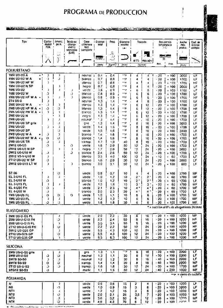
PROGRAMA DE PRODUCCION
Tip0 Contor. Anliest. Tejidode Coior Espesor Peso Oiamelro Traccion Resistencia Antho Cwi. de mldad perm. dediP. cobenvia total minimo temperatura mal. lricciin FOA miento lado 1 1 , , 'c; prcduc. campar. - silencioso transpone
i (LdB]
al 1% nixadm. !mmj [ko/m'j [mm] [N/mmj - min. 1 max. - r
OLIURETANO 1M4 UO-U0 A . lM4UO-WWA 1M4 UO-U2 HF W 1M4 U 0 4 2 N SP 1M6 UO-U2 1M6 UO-U2 W 1M6 UO-U2 HF W A * 2T4 UO-O 2M5UO-UZWA 2M5 U042 HF W A .r 2M5 UO-U2 PN W A +
2M5 UO-U2 N 2M8 UO-U0 2M8 UO-U0 SP grls 2M8 UO-U2 2M8 UO-U2 SP 2M8UO-U2WA 2M8 UO-U2 HF W A * 2M8 UO-U5 TR
2M12 V5-V-U10 W 2T12 UO-U2 W SP 2M12 UO-U15 LT W
ST 06 EL 2-U10 FL EL 2-U10 W EL W 1 5 FL EL 4420 FH EL 4-UZO W 1M6 UO-U5 FL 1M6 U3-U3 FL l M 6 W U 5 F L .
ELASTOMER0
:> I
- neulral bianco blanco negro verde blanco blanco neutral blanco blanco blanco negro
neutral gris
verde verde blanco blanco transp. verde negro blanco blanco blanco bianco
verde verde blanco verde verde blanco verde verde verde
- 0.4 0,7 0.7 0.7 0.8 0,B 0.8 1.3 1.3 1.3 1.3 1.3 1,3 1,3 1 , 4 1.5 1.4 1,4 1.7 1.6 1.7 2.4 3.5 1.6 3.0
0.6 1 .o 1 .o 1.5 2.1 2.0 1 .o 1.2 1.6 -
0.4 7
0.8 7
0.8 7
0.8 7 0.9 7 0.9 7
0.9 7 1.4 7
1.4 7
1,4 7
1.4 7
1.4 7
1.4 7
1.4 7
1.6 7
1.6 7
1.6 7
1.6 7
1.9 40 2.0 50 2.0 50 2.6 50 4.0 100 2,0 30 3.1 50
0.7 10 1.2 10 1.2 t o 1.8 10 2.3 10 2.3 20
- 4 4 4 4 6 6 6 4 6 6 6 6 8 8 8 8 8 8 8
12 12 12 12 12 12
4 2 ' 2 ' 3 ' 4 ' 4 .
6 6 6 -
A
4 4 4 4 6 6 6 8
12 12 12 12 16 16 16 16 16 16 16 24 24 24 24 24 24
4 2 ' 2 ' 3 ' 4 ' 4 ' 6 6 6 * = -
- .20 - 20 - 20 . 20 .20 .20 .20 .20 .20 - 20 - 20 - 20 - 20 - 20 - 20 .20 .20 - 20 .20 .20 .20 - 20 . l o .20 - 20
.20 - 20 .20 .20 .20 . 2 0 .20 .20 .20 ccion -
- + 100 + 100 + 100 + 100 + 100 + 100 + 100 + 100 + 100 + 100 + 100 + 100 + 100 + 100 + 100 + 100 + 100 + 100 + 100 + 100 + 100 + 100 + 60 + 100 + 100
+ 100 + 60 + 60 i 60 + 60 + 60 t 100 + 100 i 100 3 % de i -
- 3000 1700 1700 3000 1700 1700 1700 1700 1700 1700 1700 I700 1700 3000 1700 3500 1700
1700 1700 3000
1700 3000
600
1700
1700
$700
3700 1700
1700
1700
1700 1700 gamic
1700
1700
- !
- LF LF HF LF LF LF HF LF LF HF LF LF LF LF LF LF LF HF LF LF LF LF LF LF LF
MF MF LF MF MF LF MF MF MF "/mm -
2M8 UO-U-G5 FL 1 1 verde j 2.0 2.3 30 8 16 - 2 0 + 100 1200 MF 2M8 UO-U-GI0 FH J verde 2.3 2.4 50 8 16 .20 + 100 ?.?O0 HF 2M8 UO-U-GIS FL > verde 3.0 3.4 50 8 16 - 2 0 + 100 1200 MF 2T12 UO-U-GI0 FH o verde 2.2 2,2 50 12 24 -20 + 100 1200 HF 2M12 UO-G25 GP > verde 5.5 4.3 100 12 24 - 2 0 + 100 1200 HF 2T12 UO-G25 GP 3 verde 5.5 4.3 100 12 24 -20 + 100 lqO0 HF 7312 UO-G35 GP > verde 6.5 6.3 100 12 24 .20 + 100 1200 HF
I
SlLlCONA
2Mü UO-U-SO 2MTü SO-SO ZMTB 5 0 5 2 2T12 UD-u-sz 2FG12 5O-S3
POLIAMIDA
I - 5 3 O 3 O -
> u ;> O 3
gris neutral neutral transp. transp. marfil -
- I LF 2Mü UO-U-SO grls > gris 1.3 1.1 7 8 16 .20 + 100 2000 LF
2Mü UO-U-SO 5 0 neutral 1.3 1.1 30 8 16 -30 + l o 0 2900 LF 2MTü SO-SO 3 ;> neutral 1.2 1.2 30 8 16 .40 + 160 ZOO0 LF ZMTB 5 0 5 2 O 0 transp. 1.4 1.4 30 ü 16 -40 +(BO PpOO MF 2T12 UD-u-sz 3 3 transp. 1.6 1.6 30 12 24 - 3 0 + 100 1700 MF 2FG12 5O-S3 O marfil 1.1 1.5 50 12 24 -40 +250 $#O0 MF
7 = anta de cuchill. POLIAMIDA I
1.2 1.2
+ 100 2000
+ 160 2000
+ 100 1700 + 250 $#O0 7 = anta
+ 100 2900
+ 160 Ppoo
I
- LF LF MF MF
de cuchill. ~~
N > verde 0.6 0.6 15 2 4 -20 + 100 1'200 LF NE O verde 1.0 0.9 15 3 6 -20 +1W p?W LF NTl > verde 1.2 1.2 15 3 6 -20 + 100 ,1200 MF NT2 3 verde 2.0 2.1 25 36 7 - 2 0 + l o o pyoo MF NT3 J verde 3,O 3.2 50 6 12 -20 + l o o ;i?w MF NT4 3 verde 4.0 4,3 70 6 12 . 20 + i o n 1vmn .*C
* n;. .,̂ . ~: u.. ,._L:A_ -- . r , . , ..,I.lll.-.r^
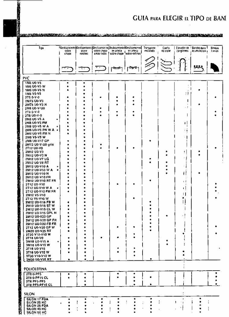
GUlA PARA ELEGIR ELTIPO DE BAN[
1M6 UO-V5 N . . . . . . . ! .
2M8 U 0 4 5 FM 2M8UO.V5WA f
2M8 U 0 4 5 PN W A f
2MB UO-V5 FM N 2M8 V5-V5 W . 2M12 UO-V7 LG 2M12 UO.V8 RT 2M12 UO-V10 A f
2M12 UO-VIO W A 2M12 UO-VIO N 2M12 UO-VIO FR 2M12 UO-V10 RT FR 2T12 UO.Vl0 . . . . 2M12 UO.Vl5 CL W . . . I 2M12 UO-V15 GPL N . 2M12 UO-V20 GP 2M12 UO.V20 GP FR 2Ml2 üGV20 FB FR 2T12 UO-VZO GP W . . 3T30 V10-V10 W 3M30 UO-V25 RT ,
! . . . 2TB O-PF15 CL 2T8 PF5-PF5 2T8 PF5-PF15 CL .

Cuello I Elwadof de Bandas para 1 acumulacid" 1 :ii
POL¡ ¿IRETAN0 1M4 UO-U0 A 1M4 U 0 4 2 W A 1M4 UO-U2 HF W 1M4 U 0 4 2 N SP 1M6 U 0 4 2 1M6 UO-U2 W 1M6 U042 HF W A . 2T4 UO-O
2M5 U 0 4 2 N 2M8 UO-U0 ~~
ZMB uo-uo SP gris 1 2M8 UO-U2 I
I ?ME UO-U2 SP 2MüUO-U2WA 2M8 U 0 4 2 HF W A * 2M8 UO-US TR 2M12 UGU3 2M12 UO-U3 N SP 2M12 UO-U10 w 2M12 VS-V-UIO w 2T12 U 0 4 2 W SP 2M12 UO-U15 LT W
ST06 ! EL 2-U10 FL EL 2-U10 W EL 3-Ul5 FL EL 4-U20,FH EL 4 4 2 0 W 1M6 U 0 4 5 FL 1M6 U3-U3 FL 1M6 US-US FL
. . . .
. . . . . . . . . . . . . . . . . . . . . . . . .
- . . . . . . . . . . . . . . . . . . . . . . . . . . . . . . . . . . -
.
.
. .
. . . . .
- .
.
.
. . . . . -
- .
.
.
. . . . . -
.
.
.
.
.
.
-
. . . . . . .
. . . . . . . . . . . . . . . . . . . .
-
-
.
.
- ELASTOMER0
2M8 UO-U-GS FL . . 2M8 UO-U-GIS FL . . 2T12UO.U-GlOFH i I 1 2M12 UO-G25 GP . 2112 UOG35 GP
. . i I 2M8UOU-GlOFH I : i : ! I ' . ! . I . . . ! 1 9 . . . . i I i o . ; . . o . . : ~
2T12 UO-G25 GP ' . / . I ' . . I . /
SlLlCONA . . I 2M8 UO-U-SO gris .. I 2M8 UO-U-SO . I . !
2MT8 SO-SO . 2MT8 SO-S2 . j . : 2T12 UO-U-52
1 * l * . I i . i 2FG12 COS3 . I . : . I
~ I I ! I . . . . ! * : . I i 1 .
POLIAMIDA
I N . . . I _ , / : I . . i N8 I ' , . : . ; . I
NT2 I i . i . 1 j , . NT4 ! ' . I . ¡ I / . I
NT1 . NT3 . . I I i
I i I .
ATENCION! Las indicaciónes anleriores son para facilitar la eleccióndel tipo de banda; se lrata de sugerencias, que de todos modos, no representan una obligacion de su cumpllmienio. '

GUlA PARA ELEGIR EL TIPO DE BANDA SEC
VC 1M6 UO-V5 1M6 UO-V5 W . .: . 1M6 UO-V5 N
2T5 O-V-O
2MT5 UO-V3 N
278 O-V-O . . 2M8 UO-V5 A . . 2M8 UO-V5 FM 2MBUO-V5W A - . . 2MBUO-V5PNWA * 1 ~
2M8 UO-V5 FM N . 2M8 UO-V17 GP 2M12 UO-V-UOgris ' ! 1 I j
1M6 V5-V5 , , ',
2MT5 UO-V3 l i i l ;
2M8 UO-V-U0 . ; [ j i ; 2T8 UO-V-O ...! I 8 1
2M8 V5-V5 W , 1 . 1 1 . 1 -
2T12 UO-VO 2M12 UO-V3 2M12 UO-V3 N 2M12 UO-V7 LG ZM12 UO-V8 RT 2M12 UO-V10 A 2M12 UO-V10 W A * 2M12 UO-V10 N 2M12 UO-V10 FR 2M12 UO-VIO RT FR 2T12 UO-V10 2T12 UO-VIO W A * 2T12 UO.Vl0 FM FR 2M12 V5.YlO 2T12 V5.VlO W 2M12 UO-V15 FB W 2M12 UO.Vl5 ST W 2M12 UO-V15 CL W 2M12 UO-V15 GPL N 2M12 UO-V20 GP 2M12 UO.V20 GP FR 2M12 UO-V20 FB FR 2T12 UO-V20 GP W 2M20 UO-VZ5 RT 2T20 V10-V10 W 3T18 UO-VO 3M18 UO-V15 A * 3Ml8 U0415 W 3T18 U0-Vl5 3T18 UO-V15 W 3730 V10-VlO W 3M30 UO-VZ5 RT I
'OLiOLEFlNA
. , i
1
j
I I 8 .
i
! i
I
I
1
I
!
.
I
. .
.
. . . . . .
.
.
. .
-
i i
! I
I ! d. /. ;. i .
1 : j
. ' O !
i ! I I ! * !
I
' i ! i I
. I . * : -
. i i
1 1 * I I
! ¡ ! I I
. '.:
* I * !
. .
I : ,
. . ZT8 O-PF15 CL I l i I : i ! ! i I : I 2T8 O-PF5
ZT8 PF5-PF5 2T8 PF5-PF15 CL
. i . ! . I < .
! ILON SILON 17 FDA
SILON 25 FDA . . . SILON 60 HC
. . . . SILON 25 HC # , / I , ' 0 , i : I I SILON 40 HC ¡ ¡ I l l * I i
, I < ,
. . , # # , I - I I / Ell n N en NII

SECTOR MERCEOLOGICO DE APLICACION
1M4 UO-U0 A 1 M4 UO-U2 W A 1M4 UO-U2 HF W 1M4 UO-U2 N SP 1M6 UO-U2 1M6 U 0 4 2 W 1M6 U 0 4 2 HF W A 2T4 UO-O ZM5 U 0 4 2 W A 2M5 UD-U2 HF W A
2M8 UO4JO SP grls 2M8 UO-U2 2MB U O U 2 SP 2MB U 0 4 2 W A 2MB UO-U2 HF W A 2MB UO-U5 TR 2M12 UO-U3 2M12 UO-U3 N SP 2M12 UO-U10 W 2M12 V5-V-üIo w 2T12 UO-U2 w SP 2M12 UO-U15 LT W
ST 06 EL 2-U10 FL EL 2 4 1 0 W EL 3-U15 FL EL 4 4 2 0 FH EL 44J20 W IMS U 0 4 5 FL 1MB U343 FL 1M6 U 5 4 5 FL .
I * /
. / . I
. I . ;
. I . !
I ! ! I
1,. I
. . . . . . . j .
. .
.;. . . ¡ I , , 1 . 1
. ; . i . , I ! i
* i i I I I :
D , .
, . ! . ! . ,
. j .
. .
. ' .
~ ' . . . . . I , ,
I
-
. .
. . . . .
. . .
-
-
. .
. . .
. . .
. . . . . . -
. ,
' 8 ' I . , ,
-
. .
. .
-
. j ! < *
ELASTOMER0 . . . 2MB UO-U-G5 FL . . . . 2MB UO-U-GI0 FH I 1 o . . . 2M8 UO-U-G15 FL . . . . 2T12 UO-U.Gl0 FH 1 . : . ZM12 UO-G25 GP . . . ! 1 2T12 UO-G25 GP ' . . . . . 2T12 UO-035 GP . . .
~ / . i j I . . . 1 , . . . . , . '
.I/ I ~
SlLlCONA . i ! ! 2M8 UO-U-SO gris 2MB UO-U-SO . ¡ . I , I . ; ! I 1 1 2MT8 SO-SO . . . 2MT8 SO-S2 ./.: 1 ; . 2T12 UO-U-S2 . . . 1 I ! I !
! , i j . 2FG12 SO-C3
'I I I POLIAMIDA
. o ,
I
. . I
N NB NT l
NT3 NT4 , ,
. . . . i I . [ / 1 i NT2 I ¡ ' ! ! o . . . . . .
, : c. I . . . . .
.-r.,,.....,. . I ., .I

How to Utilize Icons (Marks) I Each heading is shown with marks in order to make it easier to see.
. .I ~ e s c n p t i o n .'? : ~ . ! ! I , . :.' Symbol . . ,: . f Conventionaiunii->Si unit NO . . 1 Pressure MPa l k g l i c m 2 z 0.098MPa 2 ' . Foreeltoad N 1 kgl I 9.üN 3 Momenlol lOrCe Nrn l kg lm I 9.üNm
Vacuum pressure -kPa -1mmHg E -0.133kPa 4 5 Momenl of inertia kgrnz lkg lcmS2: 0.09ükgm2 6 Kinetic energy J l kg lcm 0.098J
i Mark . *
Si unii+Convenlionai unil l M P a I 10.2kgl/cmz
1N E 0.102kg1 1Nm s 0.102kglrn
-1kPa ~ - 7 . 5 m m H g l kgm 'z 10.2kglcmS2
1J = 10.2kglcm
* 2.. Meaning
MPa 0.001 0,002 0.003 0.004 0.005 0.006 0.007 0.008 0.009 0.01 0.011 0.012 0.013 0.014 0.015 0.016 0.017 kgI/crn? 0.01 0.02 0.03 0.04 0.05 0.06 0.07 0.08 0.09 0.1 0.11 0.12 0.13 0.14 0.15 0.16 0.17
MPa 0.02 0.03 0.04 -0.05 0.06 0.07 .0.08 0.09 0.1 , 0.11 0.12 0.13 0.14 0.15 0.16 0.17 0.18 kgi/crn2 0.2 0.31 0.41 0.51 0.61 0.71 0.82 0.92 1.0 1.1 1.2 1.3 1.4 1.5 1.6 1.7 1.8
MPa 0.3 0.4 0.5 . 0.6 0.7. 0.8 1 0.9 1.0 1.1 1 2 1.3 1.4 1.5 1.6 1.7 1.8 1.9 kgVcrn2 3.1 4.1 5.1 6.1 7.1 8.2 9.2 10.2 11.2 12.2 13.3 14.3 15.3 16.3 17.3 18.4 19.4
MPa 3.0 3.5 4.0 4.5 5.0 5.5 6.0 6.5 7.0 7.5 8.0 8.5 9.0 9.9 10 20 30 kgf/crnz 30.6 35.7 40.8 45.9 51.0 56.1 61.2 66.3 71.4 76.5 81.6 86.7 91.8 101.0 102 204 306
-------
Precautions to be read before handling.
0.018 0.019 0.18 0.19
0.19 0.2 1.9 2.0
2.0 2.5 20.4 25.5
40 50 408 510
Reference pages
i N '1 0.1. I O 2 1'0.3 i0.4 0.5. "0.6 0.7 0.8 . 0.9 1.0 I 1.1 I 1.2 I 1.3 kgl /0.01 0.02(0.03 0.04 0.05 0.06 0.07 0.08 0.09 0.1 [0.11 [ 0.12 0.13
; N 2 3 - 4 d 5 . . "66r :!73 8 9 10 11 12 13 14 kgl 0.2 0.3 0.4 0.5 0.6 0.7 0.8 0.9 1.0 1.1 1.2 1.3 1.4
N 30 40 50 60 . 70; 80 ' . 90 100 110 120 130 140 150 kgf 3 4 5 6 7 8 9 10 11 12 13 14 15
:"N 300 350' 400 450 500 550. 600 650 700 ,750 800 850 900 kgf 30 35 40 45 50 55 60 65 70 75 80 85 90
Indication examDle 4
1.4 1.5 1.6 1.7 1.8 1.9 0.14 0.15 0.16 0.17 0.18 0.19
15 16 17 18 19 20 1.5 1.6 1.7 1.8 1.9 2.0
160 170 180 190 200 2M
16 17 18 19 20 25
950 1000 Zoo0 3000 4oM) 5oOo 95 100 2 W 300 400 500
I- :._. ..I... ,,
I i ~ , " ,, i '"Meaning
CAD data service
Introducing "Made to Order Specifications"
Indication examole
$000 p i c a t i o n s B
International Unit Systems (SI Units) This catalog is written with SI units. I Refer to the tables below for specifications and calculations.

series a I J ~ U U
I Manifold
FOI internal p41o1 I 20
Manifold SDecifications 4 t . S d i I 42. S42
I Forexternal pilot ~ S r - . . . Manilold style
P(CUP)IR(EXH) siyie Valve slations
: 20R ..' I < ' '- . . I ' ' 4 2 R . S 4 2 ñ , ,
Single base styleIB mount
Common S U P i C o m m o n E X H 2 10 20 stations
A pon specilications
Locaiion I Valve 1 Base
Direction TOP Side PIR port
Note 1) Only lor exiernal pilot Note 2) Value when used on a manilold
How to Order Manifold Assembly Cpecily the pari numbers lo r the valve(s). blank plate assembly, and manilold base.
Example: SS3YJ3-20.03 ..---1 pc. (Manilold base) SYJ312-5LZ-M3 -2 pcs. (Valve) SYJ300-10-1A . . - . . - I pc. (Blank plate ass'y)
SS3YJ3-42R-03-C4 -1 pc. (Manilold base) SYJ314R-5G ...------.--,- 2 pcs. (Valve) SYJ300.10-2A ..-.--.-i pc. (Blank plate ass'y)
u 5 x 0.8 RC (PT)Vs nc(Pnvs M S X O B
Combinations of Soleno o Valve. Manifold Gasket and Manifo d Base
(mm2) (Cv)12 '
Body ported (SYJ302) Base mounted (SYJ304)
- 1.510.08) Base mounted 1
CYJ304iSYJ304R
VJ3M)-5-2 VJ3W5-1
Applicable b a r e Applicable base Sub-plate ggi::i:i:R I Manilold base Cs3yJ3.4i
C S 3 Y J 3 4 4 1 SC3YJ3.42 CS3YJ3-S42 SS3YJ3-42R S S 3 Y J 3 4 4 2 R
Manilold base
Blank Plate Assembly
SYJ300-10-1 A SYJ300-10-2A
VJ3oD5.2
VJ3W-5-2
Appl lsabls bass Sub.plale
ss3yJ3-42 Manilold base
SS3YJ3-41 CS3YJ3-C41
SS3YJ3.S42 SS3YJ3-42R SC3YJ3-S42R i

4/5 Port Air Operated Valve
.... series S YJA3000
Operating pressure range (MPaJ
Pi101 pressure range WPa)
Model
2 position single 2 position double
3 position 2 posilion single 2 posiiion single
0.15 Io 0.7
0.1 to 0.7 0.2 IO 0.7
Operating pressure to 0.7 0.1 to 0.7
M 3 X 0 5
Base mounted
B o d y ported
.... m-
M 3 X 0.5
22 M3 X 0.5 F
Note t ) Value when used an a manifold. Note 2) ( ): Without Sub-plate Note 3) Model No. lor 5 pan base munled style without sub-plate is SYJA3040
With Bracket SYJA302043-F Air operated
valve D B ~ I No.
The mounting bracket lor the 2 position double solenoid and 3 psition is suppled unatlached
Specifications
Mounting posiiion I Free lmpaclNibiation resislance (mls? ( I ) 300/50
Note t ) Impact resistawe: No mallumion resulted from the impact test using a drop impaci tester. The test was pertomed on the axis and ight angle directions 01 the main vahie and armature. when pilol signal is ON and OFF. (Value in the initial stage)
Vibration ieririance: NO malturnion murred in one sweep lest between 8.3 and 2WOHz. Test
P was pertomed to axls and right angle direnians Of the main Valve and armature when pilot signal is ON and OFF. (value in the Initial stage)
How to Order Manifold Base Uses Ihe same manifold baser a s the CYJ3000 series.
SS5VJA3- Tho remaindeipad nurnbei iscaned I outthe same as an SSSVJ3.
I 0.1 0.2 0.3 0.4 0.5 0.6
operating pressure (MPa)
. Speclly Ihe part numbers lor the vaive(6). blank plale assembly and manifold base.
<Example> CS5VJA3-41-03.M5 ......... I pc. SYJAJ140 ........................ , pc. SYJA240 ........................... , pc. syJ-.2t.2A ...................... a

- a
Proof pressure
Max. operating pressure
Set pressure range
Ambient and lluid temperature
Filtration
Drain capacily (cm3)
JIC symbol
1.5MPa
t .0MPa
0.05 to 0.65MPa
-5 10 6 0 % (No lreezing)
51im
8 23 45
Standard Specifications Model I AW2001 1 AW3001 I AW4001
B o w l maler ia l
Construction
Weight (kg)
Accessory [Cid. equipment) I B o w l guard
Port size I 118, 114 I t/4. 316 1 114. 318, 112 Fluid I A i ,
Polycarbonale
Relieving slyle
0.37 0.54 1.16
- O
. . . . . ... ... ,
el
Bracket
t.OMPa
0.2MPa Gauge o
10 10 u o Floai sly18 ''j N.O. <
auto drain N.C
e
Pressure ditlerenlial style auto dtain
E Ii E I
~
'' Parl No. . . . . '. AWZOOI .. I ~ - A W 3 0 0 i ~ " ~ l r . - A W . 4 0 0 1 - '
8 2 2 0 8 3 2 0 8 4 2 0 E GC30-10
GC30-2
- AD43
- AD53 AD54
I- AD62 - -

Dimensions
A W 2 0 0 1 Panel mounting
AW2001: M a x . 3.51
Y c 5
Pressure differential style auto drain
Flow direction: Right to lefl ("-R") specification

Construction
No.
JIC symbol
hi d W M I 1 d Deidpüwi
AW2001
r .
i Drain
i Drain
I Nom latenal - . .W3W1 AW4Wl I 1 Zincdiecast I Aluminum die cast 1 Painted Silver ,. Boonet Polyacelal 1 Aluminum die cast 1 Painted Black ,z 1 BMY
'& I I

Flow Characteristics COW t.om SUPP~ PfessJre O i ~ ~ a
AW3001 Rc(PTIV8
Flor turn& ANRI I
Pressure Characteristics Conditions: Supply pressure 0.7MPa Cecondav pressure 0.2MPa Flow 20 h i n ANR
AW2i
0.25
O 15
i Be sure to read belore handling. Refer Io i ; p.0.26 and 0-27 for Safely lnslruclions and : ; common precaulions on Ihe producls : mentioned in this catalog, and refer Io p.1.0-1 i : and 1 .02 lor precaulions on everv series. I
AWarning 0 The residual secondary pressure cannot be released
by releasing the supply PIessUre. To release the residual QreSSure. rontat l SMC.
[ Installation and Adjustment I 0 AWarning Set up the regulator while vtrilying the piessuis that is ii
indicated on the supply and the recondav parrure gauges. Turntng the handle e m s s i v s l y could damage the internal pans.
0 The pressure gauge that is provided with the Qrodurt lor setting a pressure between 0.02 Io 0.2MPa is the
~ r r ~~ ~
¡he adju&nt handle must be operated manually. Using a loo i to lurn be handle could lead lo damage.
ACaution ldWM 0 R e l e a s ~ t h e l ~ ~ k t o ~ ~ d l U ~ t t h e p r e s s u r e . A ~ e r l h e I.......
hi adjuslment.engage the lock. Failure to observe this procedure rould damage the
I Maintenance Inspection
AWarning 0 Replace the filler element within 2 years 01 opefalion 01
belore Ihe pressure drop leaches O.IMPa. Failure 10 obsene lhir preraulion could damage the 61ter eiemenl.
ACaution
inihe ranga o10.3tQ.03Nlm. Failure to observs lhasa torque values could lead ID equipment damage.

How to Order
. . B..;,
,
7, g, :D 4 i . ' ;
c
o
Regulator
Body size
112 AW2WI to AW4W1
Float style auto drain AW30011 (N.C.) AWN01
AW2001 Pressure d&nerential
auto drain
'Float style auto drain AW30011
Bracket
(N.O.) AW4001 Pori size ni i tm ~%t%+
. O4 112
Metal bowl 1 Accessory 1 .Symbol.( ~. ,.DeWPOon IAppEabbncdd - I ~
~~ ~
, -
Bawl guard (AWZWloniy) : C
t Jm Drain guide ;, ~ 1 (AW3Wli4Wioniy)
Non relieving style
---- With drain cock and barb fittings "W (AW3001i40010nly) r,,:'.? (For nylon 0 6 . 04)
*spew me SWWI aimanurnencay. Euunpls) 2NW
Option Combinations
Flow direction: Right lo left ("-I?' specificationl Pressure outpul por1 to gauge o1 lilter regulalor wilh integral p r e s u i e gauge is only on one side o1 the body Therelore. the specilication wilh flow direction IrOm right 10 lefl ['.R.) has a different body from the standard model. Order with the part number indicated below.
A W u 0 2 T --g G A port size
Flow direction: Right io ieH I ' Body size

Air Cylinder Technical Data@
b i r Consumption and Required Air
~~
Nominal size
TO0425 TOO604 T U 0805 TO0806
1/88 TO1075 TU1208
Air consumption and required air
0.0. 1.0. Intarnal secüonat aina l m m ) lmm) a (mm')
4 2.5 4.9 6 4 12.6 8 5 19 6 8 6 28.3 - 6.5 33.2 10 7.5 44.2 12 8 50.3
The air consumption is the volume of air that is consumed in the cylinder or in the piping between the cylinder and the switching valve dur.
ng the reciprocal movement of an air cylinder. It is necessary for selecting a compressor and for calculating the running cost.
The required air volume is the volume of air that is required for operating the cylinder at a specified speed, and it is necessary for selecting
he diameter of the piping upstream from switching valve or the FRL equipment.
- TO1209
1/48 T S 1612
3/88 TO1613
1/26 3/48
18
BAir consumption (Double acting type cylinder)
í"I77liil.
12 9 63 6 - 9.2 66.5 16 12 113 - 12.7 127 16 13 133 - 16.1 204 - 21.6 366 - 27.6 598
QCC=(Ai+AZ) X L X pi.:dy3X ........ (8) .............. Qcp=2 X a X L X 0.1013 (9)
Qc =Qcc+Qcp (10) ...................................
Occ=Air consumption o1 air cylinder OcpSAir consumption o1 tube or piping AliPislon area a l extension side A2.Piston area at retraction side
L=Cylinder stroke P=Operating pressure L=Piping length a=Piping internal sectional area
Oc=Air consumption required tor one stroke o1 air cylinder
Nhen selecting a compressor, it is necessary to select one that las sufficient capacity to accommodate the total air consumption ) f the pneumaiic actuators that consume air downstream. This is iecause air could leak in the piping en route, and be consumed )y drain valves or the pilot valves. Fulhermore. air could undergo folumetric shrinkage with the lowering 01 the temperature.
:ormula
Q c ' d c X n X Number of operating cylinder X additional rale-(t 1)
Oc'discharged llow o1 WmpreSSOr n=Numbei of cytindei cycles per one minule [ I IminIANR)] Additional rate: From 1.5
Internal sectional area of tube and steel piping
@Required air
Ord4equired air at extension side Or2=Required air at retraction side
Ai=Pislon area a l extension side &Piston area at retraction side V=Max. piston speed [mm/sl P=Operating pressure i M W
[dmin (ANR)] [dmin (ANR)] [mm? [mm2]
With the double acting cylinder, use Q r l or Qr2. whichever is greater. With Ihe single acting spring return, use Q r i , and with the single acting spring extend. use Qr2. Furthermore, if there are several air cylinders downstream from the piping or equip. ment that you wish lo select. use the maximum volume tor the total of all devices that operate simultaneously.
@Air consumption (Single acting spring return cylinder)
Formula
............. Qcc=Al X L X 10.6 (1 4)
Qcp=a X l X &X lo6 (1 5) Qc =Qcc+Qcp . . (1 6)
................. ..................................
Required air (Single acting spring return cylinder)
@Required air (Single acting spring return cylinder)
Formula
I .Or Is also shawn with Graph 14 (Page 0-23).

Air Cylinder Technical Dataw I Selection of Bore Size
.. . .~~ lmm)
12 16 20 25 32 40 50 63 80
100
When a load that is operated by a cylinder must be stopped at the end of the stroke. the piston in the cylinder will collide with the cover unless an external stopper is provided. A built-in function that cushions the impact and the sound that are generated at this time is the cushion mechanism. There are two styles o1 cushion mechanisms, as described below:
Rubber bumper: Dampens the impact sound and prevents the installation area lrom becoming loosened or damaged by the impact.
: Similar to a rubber bumper, but achieves a higher level of eHectiveness. It cushions the vibrations that are generated by collision.
Note) Depending on the mode l o1 the cylinder. it might not be possible 10 have eilher o1 the above two cushions built into the cylinder. Even if one o1 the cushion mechanisms described above is used for stopping a load, i t might not be possible to completely absorb the impact il the kinetic energy o1 the load is too large. Therelore. be careful of overloading or excessive speed. The kinetic energy o1 a load can be expressed by the formula given below. Formula
A i r cushion
(7) 1 E= 2-m X V2 ....................................
E: Kinetic energy [J] m: Load weight Ikgl V: Max. piston speed [Ws]
The following tables show allowable kinetic energy of cushion mechanism. If exceeding the energy on the tables. taking mea- sures, Such as enlargement of bore s i te and mounting of external stopper, is necessary
- Standard With Nbber bumper
0.022 0.043
0.038 0.075
0.055 0.11 0.09 0.18 0.15 0.29
0.26 0 .52
0.46 0.91
0.77 1.54
1.36 2.71
2.27 4.54
Allowable kinetic energy IJ) series CQ2
nore Si28

Air Cylinder Technical DataW
Selection of Bore Si
The relation of cylinder force. bore size and operating pressure is the following.
Formula
.................................... (1 1 (2)
Fq=q X A i X p F q X A 2 X p .................................... F1: Cylinder force at extension side [NI F2: Cylinder lo ice at retraction r i d e [NI 1 : Load ratio A I : Piston area at extension side (rnrnZ]-Reter to Table 1 A2; Piston area at retraction Side [rnrn2t.Reter to Table 1. P : Operating pressure (MPal
I I I
.AB Shown io the diagram below. the Pressure receiving alea On the retraction Side o1 the double acting single rod cylinder is reduced by the amount O1 the cross sect80nal area 01 the piston rod.
& C
A2 At
Table 1 Cylinder piston area
Load ratio q In selecting a cylinder. do not forget that in addition to the load, there are many forces that act upon the cylinder. Even in the stationary state shown in the diagram below, the resistances o1 the seals and the bearings in the cylinder must be subtracted Furthernore. during operation, recoil due to the exhaust pressure also come into play.
Siationary Action
These forces that an againsi me cylinder vary accoding to the mndiüons of the cylinder such as its size. pressure, and speed. Therefore. it is recommend- ed lo ahiays select a cylinder of a larger size. Thus. select an air cylinder so hat the load factor, which is a tanor that is usad in the selecoon process. will be as shown below. 1) To use a cylinder for stationary operations: load factor n = 0.7 or below
2) To use a cylinder tor dynamic operaüons: load tactor n = 0.5 or below (Fig. 2) 3) To use a cylinder with a guide tor horizontal aperaüons: load tactor n = 1
(Fig. I)
or below
I Figurer 1'0.7 or less
c)
Figure2 1'0.5 or less
Figure3 q=i or less
I I Note) it a dynamic high-speed operation is panicuiarly needed.
fur lher reduce the load tactor. Then, the cylinder will have power to spare lor the amount by which the load factor has been reduced. which will make it easier to produce sped.
Meanwhile. a cylinder force that has been calculated by multi- plying only the operating pressure by the pressure receiving area, assuming that no resistance exists in the cylinder. is &led a meoretical force'. Refer to Data 3. p.5.6-7 tor details on the theoretical force.
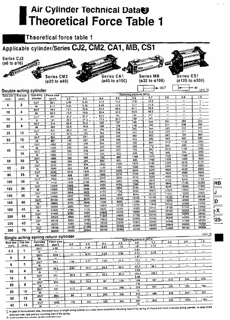
Air Cylinder Technical Data@ I Theoretical Force Table
Series CJ2 I.
Double acting cylinder I W W T [ i - $ - i N

air-hvdro
Aclion
Bore s i ze Max. operating pressure
Min. operating pressure
Cushion
Pislon speed
I -
:M2H -1lBoie sireH Stroke /[=] T
Double aclingiSingle rod
1.OMPa
O.05MPa
Air Cushion
50 Io 1000mmir
020.025, 032, 040
&Air-hydro style
i low hydraulic pressure cylinder used at a pressure of 1.OMPa Ir below. 'hrough the concurrent use of a CC series air-hydro unit, it is iossible to operate at a constant or low speeds or to effect an ntermediate stop, just like a hydraulic unit, while using ineumatic equipment such as a valve.
Act ion Bore size Proof oressuie Max. operaling piersure M i n operaling Piessute Pislon speed Ambient and livid lempefature
Thread lolersnce
Stroke tolerance
Cushion
Mounting
Double actinglSingle rod 020,025,032,040
I.5MPa I.OMPa
O.lüMPa I 5 Io 300mmis
+ 5 Io r60'C JIS class 2
t1.4 O
Rubber bumper fStandard equipmenl)
Basic. Axial twl. Front llange. Rear tlange. Single clevis. Double clevis. Front limnion. Rear Ininnion. Integrated clevis. BOSSCU~
AYto swllch can be mounted. Dimenwons are the Mme 85 the standard model.
Mounting
* Constnicüon: Reler lo p.1.4-9 .Dimensions: Reterlop.1.4-1010 1.4-18
Basic. Axial lwl. Front flange. Rear llange. Single Clevis. Double clevis. Front t~nnion. Rear INnniOn. integrated clevis, üoss.cu1
3uilt-in One-touch Fittina
Bore size i m m )
20
2 5
a 2
40
With Air Cushion
CM2I-ntingjBore sizeHstroke IA-1
With air cushion T A cushion mechanism is provided on the cover at both ends to absorb the impact that is created during high speed operations. Thus. it does not transmit vibrations to the surroundings and prolongs the lite of the cylinder.
',. Ellective cushion length
i m m i Kinetic eiiergy absorption
11.0 0.545 11.0 0.78J 11.0 1.27J 11.8 2.355
SDecifications
Action Double actinglSinqie rod
Ma l . operaling pressure
- :MZ m-1 F
T
l.OMPa
i Built-in One.louch lining
i style in which One-iouch finings are built in the cylinder. It lramatically reduces the piping labor and installalion space.
Min. operaling pressure
- Mnsmicuon: Reler Io p.1.4-9 .Dimensbns: RelertDp.1.4-1010 1.4.18 - Refer to pl.44 kn other waclFmlbns. ' . '
0.OSMPa
Mounling Basic, Axial lwl. Front Hanva. Rear flange. Single clevis. Double devis. Front uunnlon. ~ e a i trunnion. Integrated clevis. BDsscut
~~~
Rubber bumper
Built-in One-touch litling Cushion Piping Pir ion Speed 50 Io 750mmis I
ApprcaoelLDe(mm) 1 0614 1 o614 I e6 b 1 O S 6
ApplraDle tLoe mateiia. I -_ Nyion Soli nylon. Polyuielnane
d Caution The One-touch litling cannot be replaced. *The One.1wch lilting (I press.lil into the cover and canno1 be feplaced.


AN O OO/A NO 02/ANO 03/25/AN
.B
. l;.ii...
....... 9
biN,D, 0 , ................... sAN..,6 AN, ,o 0 , ................... sm. e,7 *N,rnU , U N 118 l , , ,mU , .................. w . . , 9
rY-q I ................

Pin Cylinder/Single Acting Spring Return
Series CJP H I 06,010,015
A shod stroke miniature cylinder with a shorter overall length. ThB mwllanon -0 can be sgrilicanity i&ed tecause mis cy+& can be rMe69ed direcw into a machine body or -tared cn P pane1 Thro IhR me- can be msde mae mmeacl.
Mountins Swle
mnel rmununa SNIO - .
"'il
Application Examples
Clammer
How to Order
1 Rod and mraad
32E5
Cpeclflcatlw A C M " I
Gripper stopper

Recommended Mounting Hole Dimensions for Plug Mounting Style
When plug mounted Machining dimensions for Mountino
¢= supply air
I I
Panel Mounting Style
CJPB Exhaust
~
06: C0.5 .yimE
Rod end wimout thread
Rod end nul Reterlo p 1.2.7.
Plug Mounting Style
CJPS Exhaust __ 06' CO 5
010. 15' C1
Rod end nul Referto p.1.2.7.
NN

Pin Cytinaer/singie Acting spring Return Series CJP
Siandard Strokes Weight cq I Brnrn.(rnrn) I Ea& lmnl
Plug mounting : s i
I Piping
ACaution
I ACaution
MounUnq
L

--- --- - ----- -
Bore size (mm) Rod non-rotating accuracy Style Action Fliiid Non-rotating accuracy
020, 025-0.7' 032, 040-0.5"
Can operate without lubrication.
The same installation dimensions as the standard cylinder.
Auto switches can also be mounted. It can be installed with auto switches to detect the stroke position of the cylinder.
820 1 025 1 032 I 040 ro.7" *0.5'
Air cylinder Double actingISingle rod .:.
JIS symbol
Double acíing/Single rod
Proof pressure
Made to Order
1.5MPa
Reler to p.5.4.l lor m a d e to older specilicalions I o1 series CMZK.
Min. operating pressure
SDecifications
O. O 5 M P a
Lubrication Thread tolerance Stroke tolerance Piston speed (mfnfs) Allowable kinetic energy
I *,I .
Cushion
Non-lube JIC class 2
+1.4
50 to 500 0.275 0.4J 0.65J 1.2J
Max. operating pressure 1
Auto switch model
D-C7'CB n . u m
Without au . . .... . Ambient and lluid temperature 1
Bore size (mm) 20 I 25 I 32 I 40
BM2.020 I 6M2-025 1 6M2-032 I BM2-040
2 5 . 50 . 75. 100. 125. 1 5 0 200.250.300
60 Rod Boot Materials
Nylon larpaulin
* Maximum smbisnl temperature 10, the Bailer only.
Mounting Bracket Part No.
CM.LO2OB CM-LO320 CM-LO406
Flange CM.FO320 CMX0320 CM-C040B CM.DO326
. Two Iwf Orscketr aM a mainang M! are anachM. **Cbvio @nr and rnw tinngs lmaer pins Iw b3m &e 40) are BnBulbd.
D.A'0A'A44A 0M3.020 0M3-025 0M3-032 0M3-040 D-G39A/K39A
Notel A Y! d Idloving smiles steel movnting screw i9 atla-.
iA r**fm w n m o @am is MI ammad. Please o&, VT barn
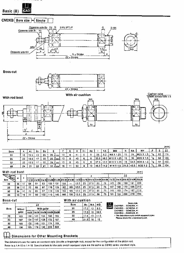
CM2KB[Boresize H Stroke 10
BOSS-Cut
. .
Cushion valve With air cushion With rod boot
l rnrnl
With rod boot i m m )
BOSS -C U t With air cushion NI W A W B
17.5 13 10.5
17.5 13 11.5
21.5 I6
Dimensions for Other Mounting Brackets
The dimensions are lhe same as standard slyle (double aclinglsingle rod). excepl lor the conliguralion o1 ihe piston rod.
Refer Io p.l.4.10 10 1.4-18. Speciiicaiions lor ihe auio switch equipped style a m the s a m e as CDM2 series standard slyle.

omRon
Horizontal
/Color Mark Sensor with Red or Green LED] -1
Verfical
- Rugged IP67 Color Mark Sensor
E3S-VSlE4
(See Note 1.)
E3S-VSlB4
H
H
E3C-VSlE42 - E3S-VS5E42G E3C-VC5E42R
E3C-VSlB43 - E3C-VC5B42R E3C-VS1842
1 rns response time Detects a wide variety of color marks PNP or NPN output models Light-on/ Dark-on operation, wire selectable Vertical and horizontal mounting styles
E3C-VSlC42 - E3S-VSlC4
Ordering Information
- -
W SENSORS
Sensing distance
Light source Mounting style
Part number - NPN w/
pull-up
resistor
PNP open
collecior
open
collector
-
- NPN
- I I I I
Note: 1. For H12 connector version o1 E3S-VSIE4 with 0.5 m cable, order E3S-VSI €4-PlJ 0.5M
M REPLACEME
Sensiliwfy adluster knob isup¡

OmRon E3S-VS E3C-VS
Part number Method of detection Supply voltage Current consumption Sensing distance
Light source
Detectable object type Operation mode Sensitivity Mutual interference protection Control outpun I solid DC I Type
Specifications .. .
E3S-VSI 0 4 0 I E3S-VS3E42G 1 E3S-VS5042R
Dinuse reflective 12to24VDC - 40 mA max.
35 mm with 2 x 2 mm 50 mm with 3 x 3 mm 12 mm with 2 x 2 mm (0.12 x 0.12 in) black mark (0.08 x 0.08 in) black mark black mark on
on white background white background on white background
Pulse modulated green LED Pulse modulated infrared LED
Color marks on colored background (see Color Combination Chart) Light-ONiDark-ON, wire selectable Adjustable Provided NPN-SPST open collector with constant current source (E3S-VSOE400) NPN-SPST open collector (E3S-VSOC4üO)
state PNP-SPST open collector (E3S-VSOB400) NPN type: Load (relay, sink) logic: 80 mA
Voltage (source) logic: 1.5 to 3 mA PNP type: Load (relay, source) logic: 100 mA
Max. load
Max. on-state 1 VDC
Response time
Circuit protection
Indicators Materiais
H OUTPUT CIRCUIT DIAGRAMS
NPN output wl pull-up reslstor
! !
I
~ -.-..
j ! ! i
! ! !
IEC colors are shown in parentheses.
!
L .,
On 1 ms m a x on 1 ms max. Output short- Provided circuit DC power supply Provided reverse polariiv
Lens Plastic Case Diecast zinc Cable sheath Plastic
Light Incident (red LED), Output Stability (green LED)
OB*-ON mele
0 "
Mounting Connections I Prewired Weight Enclosure ratings NEMA
IEC 144 Ambient temperature Operating
Storage
Dah-ON mppe
Side mounting with two through holes: Bracket E39-L2 and hardware included 3sonductor cable. 2 m (6.56 ll) length 160 g (5.64 02.)
1. 4.4X. 12 13 IP67
-25'10 55°C (-13" to 131°F) -40" to 70°C (-40' to 158°F)
Note: 1. When the Black wire from the through-team emitter is connected to the Black wire o1 the separate type receiver. the LED indicator on the eminer will indicate tight Incident on the receiver.
2. When the Black wire lrom the through-beam emitter is connected to the Blue or Brown wire of the emitter. the LED indicator on the emitter indicates Power On.

E3S-VS E3C-VS OmRon
Engineering Data H EXCESS GAIN RATIO
E3S-VSIE4(2), E3SVCI 84(2)(3) E3SVS5E42R. E3S-VCB42R
~
D OPERATING RANGE
ES-VC1 E4(2), E3SVS184(2)(3) E3S-VS5E42R, E3C-VC842R

E3C-VC omRon E3C-VC
Dimensions Unit: m m (inch)
m HORIZONTAL MOUNTING TYPES E3SVS1-4
Mounting holes
TWO MA
I 1 mi
Mounting holes
Two M4

E3S-VS omhon E3S-VS
Mounting holes
Two M4
H SENSITIVITY ADJUSTER KNOB E39-G1 (included) -4K71571
I3 I O @ d,..
\ J U
Operation H SELECTING THE PROPER SENSOR FOR COLOR MARK DETECTION The charts identity the combinations of color marks and color backgrounds that can be delected. Reler lo the illustration tor other test parameters used in preparing these sample values.
Legend: 3: Sensor detects the mark stably. X: Sensor will not deteci the mark. -: Not applicable.
Green light source (E3S-VSln4n): 35 mm. e = 90"

E3S-VS omRon E3S-VS
Red light source (E3SVS5n42R); p = 50 mm. ü =loo" to 105"
Type DC
Blue lo ( O l o ( x - ( x / o ( o Inrlinn-hliie I x I n I n I n I O I X I X - I O I n
Application Conductor Connector Pin
Brown 1 Power supply (+V)
Blue 3 Power supply (o V) Black 4 output
2 No connection -
Purple 10 I X I X j x I X 10 10 / o - / o White I O I x I X l x I x l o 13 l o l o -
DETECTING MARKS ON FILM
To detect marks on a transparent sheet (such as film). an object with a high reflection lactor must be placed behind the sheet as shown in Ihe figure at right. A mat aluminum plate is recommended.
W VO CONNECTOR PLUG
NPN output 1simneI ,.a
PNP output
T.irn"d ID.
YS2F-MZl.DCCLA XSZF-M21-Gel-A
I NOTE: DIMENSIONS ARE SHOWN IN MILLIMETERS. To convelt millimeters to inches divide by 25.4. I
omRon OMRON ELECTRONICS, INC. One East Commerce Drive Schaumburg. IL 60173 1-800-55-OMRON
OMRON CANADA, INC. 885 Milner Avenue Scarborough. Ontario M1B 5V8 416-286-6465
10199 Specifications subject to change without notice. Printed in the U.S.A. Cat. No. CEDSAX3

omRon@ r 1 1 I
ICylindrical Inductive Proximity Sensor1 I E2E I , I I
Short Barrel Metal Body Inductive Proximity Sensors in a Wide Range of Configurations
Available in prewired or quick-discon- nect versions
Quick-disconnect versions feature metal connectors for durability Easy-to-see LED indicator
w Flats for wrench tightening w Ideal for a wide variety of applications
Ordering information w SENSORS

omRon E2E E2E
Description Mounting hardware including one pair o1 metal nuts and one washer
Fils M I 2 Size sensors Fits M i 8 size sensors Fils M30 size sensors
Part Number M 1 2 4 H W S Ml84HWS M3O.MHWS
Specifications
sensing object approaching1
Control oufpul (swilching capacilyl
Diagnoslic oulpul delay Circuil proleclion Indicator
Ambient temperalure Ambienl humidity Temperature inlluence
H RATINGSICHARACTERISTICS
E2E-XDDO DC 2-wire Models
I 10% max. of sensina distance
D2 models: Load OFF
310 I O O m A ( 5 l o 1 0 0 m A l o r - M I J - T m o d e l s ) Diagnostic oulpul: 50 mA lor . D I S models
0.3 10 1 s
Surge absorber. load short-circuil proleclion (lor control and diagnosiic oulpul) D I models: Operalion indicator (red LED). operation se1 indicator (green LED) 02 models: Operalion indicator (red LED)
Operaling: -25°C to 70°C wilh no icing (-13'F 10 158°F) Operating: 35?* IO 95% 1 1 5 % max. o1 sensing dislance at 23% in lemperalure range of -25°C lo 70°C (-13°F lo
+IO*& m a l . of sensing distance a l 23°C in lemperalure range o1 -25°C l o 70°C (-13'F l o 158-F)
Voilage influence Residual voilage (see nole) lnsulalion resislance Dieieciric Strenglh Vibralion resislance
158°F)
11% max. of sensing dislance in raled voliage range f 1 5 %
3.0 V mar . (under load current o f 100 mA with cable length of 2 m) 5.0V min. lor-MIJ-Tmodels
50 M í i min. (at 500 VDC) belween currenl carry parts and case 1.000 VAC lor 1 min between curreni carry parts and case Deslruclion: 10 to 55 Hz. 1 5 m m double amplitude lor 10 l imes each in X. Y. and 2 directions

E2E omRon E2E
Enclosure UL
ratings NEMA
1
1 , 4 , 6 , 1 2 , 1 3
Approvals
_ _ _ ~ ~ ~
Engineering Data OPERATING RANGE (TYPICAL)
Shielded Models EZE-X OD O-N
~~~~
IEC 144 IP67
UL Recognized. File Number E76675
CSA Certified. File Number LR45951
o
I -15 -10 - 5 o 5 i o 15 m
Ambient operating lemperature
Vihrilinn
Y Imml
-25'10 7 0 T (-13" I o 158°F)
10 to 5 5 Hz . 1.5 mm 10.06 i n ) double amolitude
Unshielded Models EZE -XOM D O-N
-30 -?I -10 O IO x) 30
-15 -10' -5 O 5 IO Y lmml
E Z E - X O M E O I F D N EZE.XOMYO-N
-8 -6 - 4 -2 O 2 4 6 B Ylmml
-10 -5 O 5 10 15 Y lmml
-3n -m -10 o 10 a) 30 Y lmml

E2E omRon E2E - Side length 01 sensing object d (mm)
Side length o1 sensing object d (mm)
EZE-x t 0ü.N E Z E - C ~ 0 0 - N
I I o 10 I 5 m 25
Side length of sensing object d ( m m i
Operation OUTPUT CIRCUITS
E2E-XDDD-N DC 2-wire Models EZE.XClDO-N EZE.XOD1-M1J.T.N E2E.XLIDlS-N
Without Diagnostic Output No Polari ty With Diagnostic Outpu t
~ ...
o v Note: 1. The load can be connected to either the r V or O-V side.
2. The EZE.XO01-MlJ-T has no polarity. Therefore. terminals 3 and 4 tiave no polarity.
DC 3-wire Models
E2E.XClED-N NPN Output

E2E E2E
E2E-XlBMEOIFE-N EZE-XIEMYO-N
I 1 20 i c M e2 ,Dl
Side ienglh 01 sensing object d (mm)
EZE-CRBDO-N
Side length 01 sensing object d (mm)
EZE.Xl O 0 . N E 2 E X 1 0 0 - N
U 5 10 15 m n Side length o1 sensing object d (mm)
Operation OUTPUT CIRCUITS
E2E-XODO-N DC 2-wire Models
EZE-X.3DO.N E2E.XDD1-M1J.T-N
Without Diagnostic Output No Polari ty EZE-X OD 1 S-N
With Diagnost ic Outpu t
Note: t . The load can be connected I o either the +V or 0.V side.
2. The E2E-XOOt-MIJ-T has no polarity. Therefore, terminals 3 and 4 have no polarity.
D C 3-wire Models EZE.XOEZ-N
NI” Output
I I -&a ” ov
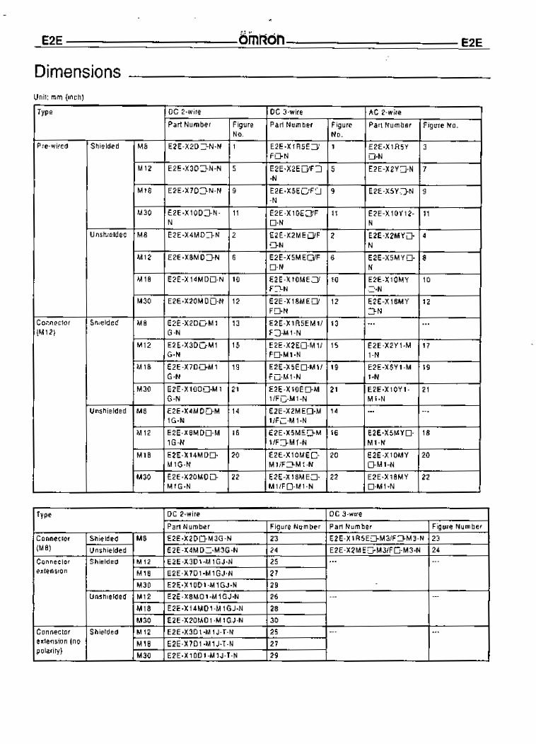
ómrion E2E E2E
Type
Dimensions
I DC 3.wire 1 AC 2.wire DC 2-wire Par l Number 1 Figure 1 Part Number I Figure 1 Part Number I Fiaure No.
Type
Conneclor Shielded M8
Unshielded (ME)
Connecior Shielded M i 2 M18 exlension
M30 Unshielded M 12
DC 2-wire DC 3-wire
Par lNumber Figure Number Part Number Figure Number E 2 E - X 2 D D M 3 G - N 23 EIE-XlR5EO.M3/FO-M3.N 23 EZE-X4MDO-M3G-N 24 EZE-XZMEO-M3/FO-M3-N 24 E2E-X3D l -M lGJ-N 25 EZE-X7D!-MlGJ.N 27 E2E.XlODI.MlGJ-N 29 E2E.X8MD1 .M 1 GJ-N 7 6 ... ~~~
... ...
Connecior exlenslon (no polartly)
_ _ M18 EZE-X14MDl -M lGJ-N 28 M30 EZE-X2OMDl-M1GJ.N 30
... Shielded M12 EZE-X3D l -M lJ -T -N 25 ... M18 E2E-X7D l -M1 J-1-N 27 M30 E2E-X 1 OD1 -M 1 J-T-N 29
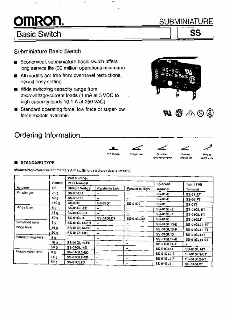
omRon. 1 Basic Switch
SU BM I N I ATU R E
Subminiature Basic Switch rn Economical, subminiature basic switch offers
long service life (30 million operations minimum) rn All models are free from overtravel restrictions,
permit easy setting Wide switching capacity range from microvoltagekurrent loads (1 mA at 5 VDC to high-capacity loads 10.1 A at 250VAC)
B Standard operating force, low force or super-low force models available
I
w a d @ @
Ordering Information
A Lc a d L 2 Pin plunger Hiwe lele, Simulated Formed ningea
mllei hinge lwei hinge lever roller lever
STANDARD TYPE
Microvollage/mlcrocurrent load 0.1 A rnax. (Bifurcated crossbar contacts)

ooi w o 3
ív s 01 1'0 i e palei slapow piepuais) (V S'O 01 1'0 i e Palei slapow piapuais) (sa!ias aqi tnoq6noiqi uowwoa)
.3N-lSdS .ON-1SdS l a d s WüOJ 13WlN03 W

ss omRon ss
Contact rating: Normal operating lorce models (CS-'~')
Low operaling lorce models (SS--~.F)
Super-low operating force models (SS-: :E) Lead wire models (ail OF types)
5s-o11 ss-SE. ss-10: 0.1 A 3 A o r 5 A 10.1 A 50 mn 30 m n 30 m n 100 m n 50 mn - 150 mn - - 100 m n 50 m n -
Characteristics
Note: 1 . SS-10 Series only. 2. 50.000 operations minimum lor lhe SS-10 series. 3. Applies lo the pin plunger type (at the pin plunger o1 the lever type). 4. 10 million Operations lor the SC-10 series. 5. Data shown are of initial value.
3

ss omRon ss
CHARACTERISTIC DATA
Mechanical service life Standard type (CS-5. SC-10 series)
Electrical service life Standard type (CC-5 series)
Raled Operating Current ( A l
Dimensions Unit: mm (inch)
H STANDARDTYPE
Pin plunger 7.5
CC-O1 (-E, -F) SC-5 (-F) CC-10
Note: 1. Unless otherwise specified. a tolerance of f 0.4 mm applies to all dimensions. 2. Straight vertical PCB terminal models are shown above. Soldered terminal, Tab (#IO) terminal. lead wire terminal. PCB
terminal parallel to ieil and PCB terminal parallel to right are shown in the Terminals section.

ss omRon ss
Super-low force Low-force models Operating model SS-OIGL-F characteristics SS-OIGL-E SS-5GL-F OF max. 8 9 16 9 RF min. 1 g 2 9
Hinge lever CC-O1GL (-E, -F) SC-5GL (-F) CS-IOGL
Standard models Standard SS-OIGL model SS-5GL SS-IOGL 50 g 50 g 6 9 6 g
4 (0.16)
OP 8.8 i 0.8 mm (0.346 f 0.032 in)
8.8 i 0.8 mm (0.346 i 0.032 in)
8.8 f 0.8 mm (0.346 i 0.032 in)
8.8 i. 0.8 mm (0.346 f 0.032 in)
OT min. MD max. FP max.
I 1.2 mm (0.472 in) 1 0.8 mm (0.032 in) j 13.6 mm (0.535 in)
I 1.2 mm (0.472 in) 1 0.8 mm (0.032 in) I 13.6 mm (0.535 in)
j 1.2 mm (0.472 in) I 0.8 mm (0.032 in) I 13.6 mm (0.535 in)
I 1.0 mm (0.039 in) 1.0 mm (0.039 in)
I 13.6 mm (0.535 in)
Operating Super-low force Low-force models Standard models Standard model SS-O1 GLI 3-F SS-OlGL13 model
Simulated roller hinge lever CS-OlGL13 (-E, .F) CS-5GL13 (.F) SC-lOGL13
4 (0.161
Note: I . Unless otherwise specified. a tolerance of * 0.4 mm applies to all dimensions. 2. Straight vertical PCB terminal models are shown above. Soldered terminal. Tab (#IO) terminal. lead wire terminal. PCB
terminal parallel Io left and PCB terminal parallel to right are shown in theTerminais section.
5

ss omRon ss
I 1 Super-low force I Low-force'modeis Standard models .I SS-OIGLI4
characterist1CS I SS-OlGL14-E [ SS-5GL14-F SS-5GL14
Unit: mm (inch)
Formed hinge lever CS-01GL14 (-E, -F) CS5GL14 (-F) CC-10GL14
Standard model SS-lOGL14
4 1
(0.16)
1 Ooeratino 1 model I SS-OIGL14-F
I (0.398 f 0.032 in) I (0.398 + 0.032 in) 1 (0.398 f 0.032 in) (0.398 10.032 in) I
Hinged roller level SS-01GL2 (.E, -F) SS-5GL2 (.F) SS-IOGL2
Note: Unless otherwise specified. a tolerance of M . 4 mm applies lo all dimensions.
H MOUNTING HOLES
Standard types Mounting holes below are for reference only.
TW 2.4 du. rnounwq '5.25 mna1.Jsb 1.5dlLh*
""' --$ (0.211 ,::$f-& ; r-T-f
(0.37S.W)
1 6 B.8:: 10061
16 I t 0 1 ~0.6)10.001)
Note: Unless otherwise specified. a tolerance of * 0.4 mm applies lo all dimensions.

ss omRon ss
H TERMINALS
General-purpose type
PCB terminal, straight vertical (D) PCB terminal, parallel to left (DI) PCB terminal, parallel to right (02)
Note: Thickness o1 ail the terminals is 0.5 mm.
Soldered terminal (blank) Quick-connect tab ( f l l O ) terminal (T)
APPROVALS
UL (File NO. E41515)KSA (File No. LR21642)
SC-10 senos 1 General-purpose type I 10.1 A, 25OVAC SS-5 series 1 General-purpose type I 5A.125V.3A250VAC CS-01 senes I Super-low force type I 0.1 A. 125 VAC. 30 VDC
VDE (File No. 5861-3221)
Type 1 Rating SS-5 series I General-purpose type 1 5 A, 25OVAC
SEMKO (File Nos. 43-8614026143-891609)
Type 1 Rating SS-10 series I General-purpose type 1 10 A. 250 VAC SS-5 series 1 General-purpose type I 5 A. 250 VAC
Note: The rated Values approved by each of lhe salely standards (e.g. UL. CSA) may be different from the performance characteristics individually defined in !his catalog.
omRon OMRON ELECTRONICS, INC. One East Commerce Drive Schaumburg. IL 60173 1-800-55-OMRON
OMRON CANADA, INC. 885 Milner Avenue Scarborough. Ontario M1B 5V8 41 6-286-6465
4/98 Specifications subject lo change without notice. Prinied in the U S A Cat. No. GC CW5
7

omRon 1
Appearance
I E E -S B5 M IS B5M C/S B5V/S B5VC/S B5V-E
Sensing method Sensing distance Oulput conliguralion Weight Par1 n u m b e r Retleclive 5 m m Light-ON Approx 3 O g EE-SBSM
Dark-ON EE-CE5MC
Lighl-ON EE.SB5V
Dark.ON EE-CB5VC 19 m m Lighl ON Approx 2 8 g EE-SB5V-E
L J
Item
Supply voltage Cutrenl consumption Maximum forward direct currenl (IF) Forward voilage (VF) Reverse vollage (V,) Standard reference object Diflerenlial distance
Photomicrosensor with 80-mA Switching Capacity that can be Built into Equipment
Built-in amplifier 1 Models available with 5- to 12-VDC and
5- to 15-VDC input
CMOS- and TL-compatible
Model with easy adjustment with an external sensitivity adjuster (EE-SB5V)
Special connectors (EE-1001/1006) are available
19-mm sensing distance (EE-SB5V-E)
Convert to PNP output with EE-2002 conversion connector
Relleclive
5 lo 12 VDC f 1 0 % . ripple ip-p): 10% max. 36 mA max.
- 30 mA max. -
E E 6 0 5 M I EE-SB5MC EE.SB5V(-E) 1 €E-SB5VC 5 10 15 VDC f10%. ‘ipple (p.p): i o s i m a x . 48 m A max. (DC current: IF = 25 mA)
1.5 V max. (IF = 30 m A )
4 V max. - White Paper with refleclion lactor of 905% (standard sensing object: 15 x 15 mm) 0.1 m m
Ordering Information
Specifications

S p e c i f i c a t i o n s Table - continued from previous page
'The response frequency was measured by delecl ing i h e following disks rotaling.
Ambient temperature
Ambienl humidity
Operating Siorage
.25:C lo 55 'C (-13'F to 131°F)
-30% to 8O'C (.22"F to 176°F)
Operating 4 5 % to 85% Storage 35:'. to 95%
Vibration resistance
Shock iesislance Soldering heat resistance
Destruction: 20 to 2.000 Hz (with a peak acceleration o1 ZOG's), 1.5-mm double amplitude lor 4 min each in X . Y. and Z directions
Destruction: 500 mis2 lor 3 times each in X. Y, and z directions 26Ooi5'C (See Note.) when the portion between the lip o1 the terminals and the posi l ion 1.5 m m from the terminal base is dipped into the solder lor l o t i secondS

Engineering Data OPERATING RANGE (TYPICAL 1) OPERATING RANGE (TYPICAL 2)
X (mm)
SENSING DISTANCE VS, AREA (TYPICAL)
OBJECT SENSING DISTANCE VS. I, EE-SB5V-E (TYPICAL)
Area (mm2)

EE-SBSMISB SMCICB SVIC B5VC/CB 5V-E -E E-SB 5MIC B5M CIS B5VISB5V CICB 5V-E
O peration INTERNALEXTERNAL CIRCUIT DIAGRAMS
EE-CBSM(C) Light-ONIDark-ON EE-CBW(C), EE-CB5V-E Light-ONIDark-ON
r - -
L
TIMING CHART
Light-üN Dark-ON
Dimensions Unit m m (inch)
E E-SB5M (C), E E -S B 5V(C), E E-SB 5V-E
25.411.Wl 19.0 10.751 -71
695 1027)
10011
Terminal Arrangement
~~
OUT [ O U T P U T (4)

EE-SE5M/SE5MC/C~5V/SESVC/SB5V-E - OmRon - EE-SE5M/SE5MC/SE5V/SE5VC/SB5V-E
W EE-SB5M(C)/SB5V(C)/SB5V-E t EE-1001 W EE-S B5M (C)/SB5V( C)/SB 5V t EE-1006
W EE-1001 CONNECTOR
IO 241
4 W EE-1006 CONN C R WITH CABLE
Terminal Arrangement
IEC colors are shown in parentheses. Note. Supply 5 10 I 2 V lo the E E . S B S M ( C ) . Wire a s shown by the lollowing diagram i f the supply voltage exceeds 12 v. .-___
--Q .-.-k&? ., . ci vcc O1
2 2 ~ vcc121~vccll I . - 2 2 . R
GND i, ..-.?
v --'

EE-SBSMISB5MCISBSVISB5VCICBSV-E " m n r \ n E E - S B S M / S B 5 M C / S B 5 V / S B 5 V C I C B S V - E
Precautions ilmT vcc
Refer to the Technical Intormation Section tor general precautions.
An external sensitivity adjuster can be connected to the
the sensitivity adjuster. inserI resistor R F (current-limiting
as tollows:
n OUT EE.SE5V(C). EE-SB5V.E Photomicrosensor. When connecting Enema1 renriiivity adjwler
resistor). as shown by the diagram. The value of R F is obtainable L :,p"t R F > (Vcc - 1.5 V)/30 mA
Note: The EE.SB5VIC) and EE-SE5V-E have no constant current c i r c ~ i t t o protect the LED. Fo r lh i s reason. Ihe LED will be damaged by excessive current applied Io Ihe posilive terminal. TO prevent polential LED damage, connect a current.limiting resistor, as shown previously.
NOTE: DIMENSIONS SHOWN ARE IN MILLIMETERS. To converl millimeters to inches divide by 25.4.
OMRON CANADA, INC. 885 Milner Avenue Scarborough. Ontario M i E 5va
416-206-6465
omRon. OMRON ELECTRONICS, INC. One Eas i Commerce Drive Schaumburg. IL 60173 1-800-55-OMRON
Cat. N.O. E 0 5 D A X 4 1/99 Specifications subject l o change without notice. Prinled in U.S.A.

E2E omRon E2E
AC Shielded M18 Fig. 31: E2E.X5Y ü.53.US
185dia IO 7281
AC Unshielded M I 8 Fig. 32: E2E-XIOMYD53-US
24 10.9451 Ml8 P=l.O
AC Shielded M30 Size AC Unshielded M30 Size E Z E - X I O Y 3 - 5 3 4 S Fig. 34: EZE-Xl8MYÜ-534iS Fig. 33:
M10 P;,.5 5(02(11 36 (:.dl71 Indicelor
36 11.417) 10.061, BClOSS 111s
!
Installation
CONNECTION
EZE.XJD3-N D C 2.wtre Models í w i t h o u t Diagnostic Output) E 2 E - X 3 3 - N A C 2.wire Models
Note: The load can be connected as ahown above.
EZE.XOD1S-N DC )-wire Models (With Diagnost ic Output)
Note: The control ouiput and diag. nostic output share the nega- tive common terminal. There- fore. the loads must be con- nected to the positive sides of the conlrot output and diagnostic output.
E2E-XODI-MIJ-1.T-N DC 2.wire Models (No Polari ty) EZE-XOYO-N A C 2-wire Models
Blue
Note: There is no need to be con- Cerned about the polarity (BrownIBlue) o1 the Proximity Sensor.

ULN2001 A-ULN2002A ULN2003A-ULN2004A
ULN2001A
ULN2002A ULN2003A ULNZ004A
SEVEN DARLINGTON ARRAYS
General Purpose, DTL. TTL. PMOS, CMOS 14-25V PMOS 5V TTL, CMOS 6-15V CMOS, PMOS
m SEVEN DARLINGTONS PER PACKAGE . OUTPUT CURRENT 500mA PER DRIVER
DIP16
ORDERING NUMBERS: ULN2001N2Ai3N4A
SO16
ORDERING NUMBERS: ULN2001 DDDDDi4D
PIN CONNECTION
I
IN I
IN 2
IN 3
IN 4
IN 5
IN 6
IN 7
GNO FREE ,DRx#s
September 1998 1 I8

ULN2001A - ULN2002A - ULN2003A - ULN2004A
SCHEMATIC DIAGRAM
r"'" ?-O-
.- EACH a n V E R I 5-JUY
Series ULN-2001A (ea& driver)
L - * _ _ - _ _ _ _ - _ EACH DRWER
Series iJLN-2OOZ (each driver)
F C O M
I I I
EICH W E R
I N Y - o " I m n ikn I
I I L -*- _ _ _ _ - - - - L -*- - - _ - _ _ _ _ - 1
EACH DRIVER S-Z,,.
Series ULN-2004A (each driver)
Series ULN-ZOOM (each driver)
ABSOLUTE MAXIMUM RATINGS
THERMAL DATA

ULN2001A - ULN2002A - ULN2003A - ULN2004A
IC = 275mA IC = 350mA
for ULN2001A
ELECTRICAL CHARACTERISTICS (Tarnb = 25OC unless othewise specified)
_ _ IC = 100mA. IB = 250pA
IC = 350mA. IS = 500pA for ULN200ZA. V, = 17V tor ULN2003A. V, = 3.85V for ULNZ004A, V, = 5v v, = 12v Tam = 70°C. IC = 500pA VCE = 2 v for ULN2002A
for ULN2003A
IC = ZOO mA, IB = 350pA
IC = 300mA
IC = 200mA IC = 250mA IC = 300mA
IC = 125mA for ULNZ004A
Symbol Parameter
50
VCE(~,,,
IilOnl Input Current I Collector-eminer Saturation Voltage
DC Forward Current Gain
Input Capacitance
, I VF I Clamp Diode Forward Voltage
Tam = 7 0 " C , V c ~ =50V
Tamb = 70°C for ULNZOOZA
tor ULN2004A VCE = 50V, V, = 6V
VCF = 50V. Vi = 1V
0.9 1.1 1.3
0.82 0.93 0.35
1
65
-
-
- ~
ramD = 70'C. vn = 50V
1 1.7 F = 350mA
500 1 pA 1 I b
1.25 mA 1.35 mA 0.5 mA 1.45 mA
2

ULN2001A - ULN2002A - ULN2003A - ULN2004A
TEST CIRCUITS
Figure la . Figure 1 b.
1 S - 5 T l S
Figure 2.
I ORNQ ~1
5- 19.4
Figure 4.
I I
Figure 6,
Figure 3.
P Figure 5.
Figure 7.
I I
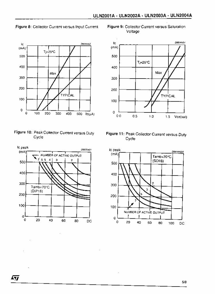
ULN2001A - ULN2002A - ULN2003A - ULN2004A
Figure 8: Collector Current versus input Current Figure 9: Collector Current versus Saturation Voltage
0.0 0.5 1 .o 1.5 Vce(cat)
Figure 10: Peak Coilector Current versus Duty Figure 11: Peak Collector Current versus Duty Cycle Cycle
D96/NdSf IC peak
O 20 40 60 80 DC O 20 40 60 80 100 DC
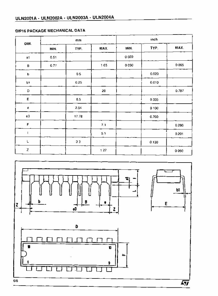
ULN2001A - ULN2002A - ULN2003A - ULN2004A
mm
MIN. TYP. MAX. DIM.
al O 51
B o 77 165
b 0 5
inch
MIN. TYP. MAX
o O20
O 030 O 065
o 020
I b’ I D
I 0.25 1 20 0.787
1 0.010 I
E l 8.5 0.335
I 2.54 I e3
F
I
L
z
17.78 0.700
7.1 0.280
5.1 0.201
3.3 0.130
1.27 0.050
-I O I t
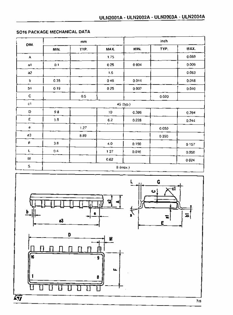
ULN2001A - ULN2002A - ULN2003A - ULN2004A
DIM.
A
SO16 PACKAGE MECHANICAL DATA I
rnrn inch
MIN. TYP. MAX. MIN. TYP. MAX.
1.75 0.069
-
a1 0.1 0.25 0.004 0.009
I 1.6 I
S
I 0.063 , 1
8 (max.)
t D

ULN2001A - ULN2002A - ULN2003A - ULN2004A
lnlormallon lurnished is believed 10 be accurate and reliable. However. STMicroelectrmics assumes no responsibility lor Ihe conse- quences 01 use o1 such inlormalion nor lor any inlfingemeni o1 patents or Other rights o1 third panies which may result lrom its use. No license is granted by irnplicalion 07 othewi5e under any palenl or Patent righis o1 STMicroeleclronics. Specil iqion mentioned in lhis publication are subject to change Without notice. This publlcallon supersedes and replaces all inlormation previously supplied. STMi- Croelectronics products are not authorized lor ~ 5 e as cilical components in lile suppan devices or sysIem5'witho~t express written
The ST logo is a regisleredtrademark o1 STMicroeiectronics e I998 STMicroelectionics - Printed in Italy - Al\ Rights Reserved
STMicroelecIronics GROUP OF COMPANIES Australia . Brazil . Canada - China. France, Gemany. Italy .Japan -Korea. Malaysia - Malla. Mexico . Morocco . The Netherlands .
approval o1 STMicroelectmnics. . . .
Singapore - Spain . Sweden . Swilzeiland . Taiwan - Thailand. United Kingdom. U.C.A.

Decembef 199'
N a t i o n a l S e m i c o n d u c t o r
LMD18200 3 A , 55V H-Bridge
No 'shoOt.thiOYgh' cuiient m Thermal warning llag output at 14S.C
Gen era I Description' The LMD18200 is a 3 A H-Bridge designed 10, motion COntrol application$. The device IS built using a mutti.technology pro. res$ which combines blpola l and C M O S control C i r C ~ i t r y with DhlOS power devices on the same mondithic ~ t ~ u c i u ~ e , Ideal lo r driving DC and stepper motors: the LMD18200 ac.
a t 170'c ' lnteroa1 'lamp Shorted load Protection . Internal charge pump W i t h external bootstrap capabil i ty
commadater peak output current6 UP to 611. An innovative circuit Which taci l i tates low-106s renring elthe O U ~ P U I C W ~ " ~
ha$ been implemented. Applications
DC and s t e m e r motor diiver
I Tit and CMOS compatible inputs
Functional Diagram
DIRCCTWW
ERAKC
PWY
8 CURRCNT SCHSC OUTPUT
I- s O
wouno o%:<&,
F IGURE 1. Funcllonal Block Diagram o1 LMD18200
.. .

Connection Diagrams and Ordering Information
O
BwpSlRAP 2
OUTPUT 2
MERMAL FUC OUTPUT
CURRENl SlNSE 0mLn
CROUND
vs POWER SUPPLY
PWM INPUT
BMKE INPUT
OlRECrnU IUPLn
ouwur I
Bwnw 1
MDUNlMG TAB CONNICTCD TO CROUND (PIN 7)
11-Lead TO-22D Package Top View
Order Number LMol82OOT S e r NS Package TA110
Top View Order Number LMol82OOT
S e r NS Package TA110
V O U T I A d DiRECTlONA 3
B W A 4
PWMA 5
Signa G$ Cu”Bn1 s e w B
mamul n a g B
VOirr2.9 1’ BOOTSTRPPZB 12
I
’OUT24
nmw,s , .> , 24-Leild Dual-in-Line Package
Top View Older Number LMD1820D-2D.OV
596242325DlVXA LM01B200~2DIBñ3 596242325DlMXA
See NS Package 011248
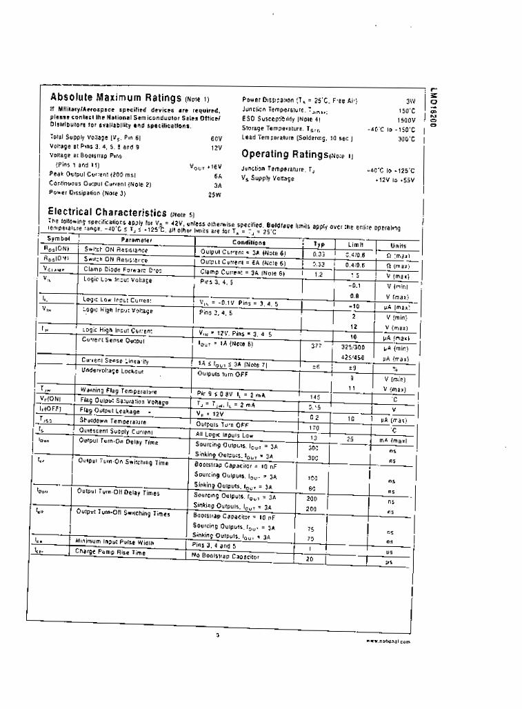
Absolute Maximum Ratings (Note I )
II Ml l i Ia iy lAe iorpacr specit led devices are required. please sonlac t lhc National Semiconductor Sales Otfical Di l l l i lbUIOrs tor avllilabltity and speci l lcal lons.
Total Supply Voilage IV,. Pin 6) 60V Voltage a l Pins 3. 4, 5. 8 and 9 12v Voltage a t BootBt<ap Pi"$
Y,,, i l 6 V Peak Outpul Cuirent (200 mr) 6A Coniinuour Output Cuiient (Note 2) 3A
Power Dissipation (Naie 3) 25W
!Pins 1 a n d 11)
P o w e r Dissipation (T. = 25 'C . Free Ai!)
Junction Temperature. T,,,.., 150 'C
ESD Susceptibility (Nole 4 ) i saav
3w
Storage Temperalure. T,,, Lead Tempemlure (Soldering, 10 l e c . )
-4G'C io -1SO'C
30G'C
Operating RatingsiNole 1 1
Junction Temperalure. T, - 4 a . c to .125'c V, Supply Voltage +12V to *55V

Cutrent Sense O u t p ~ t VI Load Currant
Ro,ION) Y S Temperature
supply current "I Frequency (V, = 4LV)
Cvrrent senre Operating Region
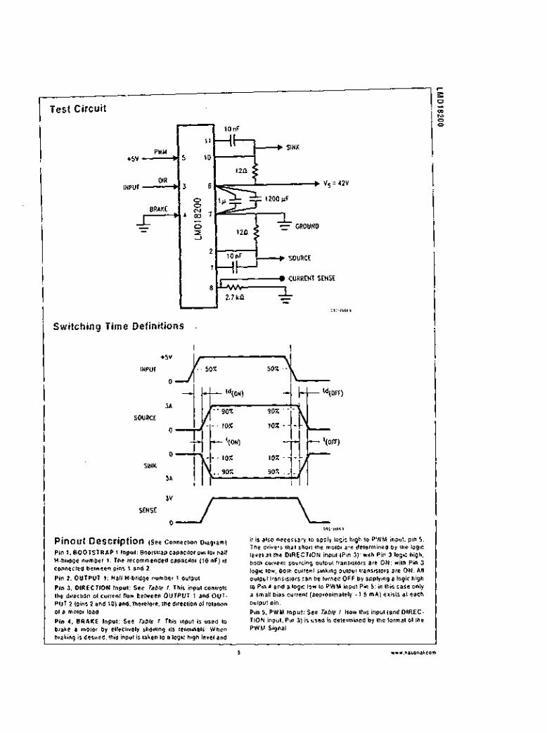
Test Circuit
PWU r5v - - t o n F
11
10
SINK
CURRENT SíNSE
0101b111 I
Switching Time Definitions ,
INPUT
SOURCE
SINK
3v I
SENSE O J L I Pinout Description (see connection D ~ ~ ~ ~ ~ ~ ) it _ _ ~ is also ~ ~ ~ . . ~ _ ~ . ~ necessary l o apply logic high lo PWM input. _ _ pin 5.
Pin 1. B O O T S T R A P 1 Input! BoolrliaP c ~ ~ a ~ i t o l pin tor hall H.bridge number I. The iecommended capacitor ( t o OF) is connected belween pins t and 2.
Pin 2, OUTPUT 1: Hall Wbiidge number 1 oulpul.
Pin 3. DIRECTION Input: See Table I . This inputcontrotr the direction o1 culrenl llow between OUTPUT I and OUT. PUT 2 (pins 2 end 10) and. Ihereloie. lhe direction o1 rotation o1 a malor load.
Pin 1. B R A K E Input: See Table I . This input is used l o brake a motor by enscliveiy shorting its leiminals. When braking is desired. this input is taken to a logic high level and
, " e orwer5 inai Inor, me rnoror are orierii i lnrQ O" m e 1og" level al lhe DIRECTION input (Pin 3): with Pin 3 logic high, both current rauicing output tran6i6tOis are ON: with Pin 3 logic low. both Curlent rinhing O W u t tranBi$tülB are ON. All o ~ t p ~ I l r a n ~ i ~ t ~ r s can be turned OFF by applying a logic high Io P i n 4 a n d a l o g i c l o r i l o P W M inpulPin 5: inthircaSeonly a m a l t bias Cuirenl (appmximately - 1 . 5 mA) eiiSlS 81 each 0"Ip"t pin. Pin 5. PWM Input: See Table I . HOW this Input (and OIREC. TlON inpul. Pin 3) is used ib delemined by Ihe loimal o1 Ihe PWM Signal.

Pinout Description (See Connection Diagram) (Continued)
Pin 6, Y, Power Supply
Pin 7, GROUND Connüclion: This pin is the grüund return, and i s internally connetled to t h e mounting tab. Pin 8. CURRENT SENSE O ~ t p u t : This pi0 provides the souicing cuiient sensing output signal, which 1s typically 377 pAIA.
Pin 9. THERMAL FLAG Output: This pin provides Ihe ther. m a l warning llag OYIPUI signal. Pin 9 becomes i lcIrve-low at 145 'C (1~11~11011 temperature). H o w e ~ e r the chip wil l not shut ilseit down unlil l l O ' C Pin 10, OUTPUT 2: Hal l H-bridge number 2 Outpüt. Pin 11, BOOTSTRAP 2 inpul: 8001~1rap ~ a p m l ~ r pin lor Halt H.bridge number 2. The recommended capacitor (10 nF) t i connected between pmr 10 and I1
ieachae 81 the iunclion.
TABLE 1. Logic Truth Table
PWM 1 Di, I Brake I AciIve Output Drivers
H I H I L 1 Soutce 1, Sinh 2 1 1 ; 1 ; 1 Sink I. Source 2
source I . souice 2
source 1 , source 2
H Sink 1 , Sinh 2
X H NONE
Application Information TYPES OF PWM SIGNALS
The LMDIBZOO ieadily interlaces with dinerent loims 0 1 PWM signair. Use el ihe part with two o1 ihe mole populai t o m s o1 PWM is described in the following Paragraphs. Simple. locked anli.phasa P W M consists 01 a single. vaii. able duly.cycle signal in which is encoded both direction and BmDlilYde inlotmation (see Figure a. A 50% dU:y.Lycle P W M signal represents zero drive. since the net Y ~ Y B 01 YolIa9e (integrated over one period) delivered lo Ihe toad i s 2elD. For the LMOIB2OQ. the P W M signat driver the diiec- tion input [pin 3) and the PWM input (pin 5 ) is tied IO logic high.
FIGURE 2. Locked Anti-Phase PWM Control
Signlmagnllude P W M con~lists o1 separate direction (sigo) and amplitude (magnitude) signals (see F@um 31. The jab- solute) magnitude signal is d u t y q c l e modulated, and the absence 01 a pulse signal (a c o n t i n ~ o ~ s logic low level) i ep - resents zero drive. Cuiient delivered to the load is propol. t ional Io pulse width. Far the LMDiñ200. the DiRECTlON m- pul (pin 3) to driven b y the sign signal and the PWM inpvl (pin 5 ) is driven by the magnitude Signal.
ILm - I.9
.--_n- 04m I DW"", I
YOTORSPEED nc. - r.9
.--R_m - I D - ,
1)1110<11.,
FIGURE 3 . SignlMagnilude P W M Control
SIGNAL TRANSITION REOUIREMENTS
To ensure proper inlernat logic pertormame. il is good prac. tire to avoid aligning the tsliing and rising edges 0 1 input sig- nals. A delay o1 81 leas: 1 vfec s h w i d b e incoiporaled be. tween IranSiIiOnr 01 the Direction. Brake. andlor P W M inpul Signals. A cOnsewBI Iv0 approach 1s be suie there is a l least 500n6 delay between the end 01 the l i i s l tian6ition and the beginning 0 1 the second transition. See Figure 4.

- ~~
Application Information (Continued)
, < < <
I .
FIGURE 1. Tisnritionr in Brake. Direction. or PWM Must Be Separated By A t LCIS~ 1 psac USING THE CURRENT SENSE OUTPUT The CURRENT SENSE 0u:~uI (pin 0) has a rensitivity O1
377 pA per ampeie o¡ ob' m i e n l . For Optimal accuracy and Iineaiity o l th i s signa' . .due of voltage generaling re. s i m i between pin 8 anfl ', , i ld should be charen 10 limit the maximum voltage developed a l pin 8 10 5V. or less. The maximum voltage cornpilance is t Z V .
I t Should be noted that the reciiculating curients (tree wheel- ing c u r m i s ) a t e ignored by the current sense circuitry. Therefore. only the current6 in the upper rouicing outpyts are sensed
USING THE THERMAL WARNING FLAG
SiStOl . This permits a *ired O R Connection 01 thermal wain- in9 [lap OuIpuIS from multiple LMD18200'S. and allows the use! Io se1 Ihe logic high level o1 the output signal swing to match rysirm iequirementr This oulput typically drives the inleiwpi inpul ot a ryrlem controiiei. The inlerrupt service routine would then be designed to take approptiate steps. such as reducing taad c u v e n t ~ or inittating an Orderly system shutdown The maximum voltage Compliance on the flag pm is tzv.
SUPPLY BYPASSING
TheTHERMAt FLAG o u t p ~ t j p i n 91 i ran Opeocotlectoriian.
During switching transitions Ihe Ievets o1 last current Changer experienced may Cause tioubtesome voltage (ran- Sien15 B C l O I s system Sl iSy inductance.
If i l nOCmally neCeSraV to bypass the Supply rai l with a high qualily capacitoqsl connecled a5 close as possible to the v, Power Supply (Pin 6) and GROUND lPin 7). A 1 pF high4iequency Ceramic capacilor IS recommended. Care Should be laken to limit the transient6 0 0 the supply pin be.
atmg the chip at supply voitages above 40V a voltage sup. Plessol ( t ianíoibl such as P6KESZA is fecommended from supply 10 ground. Typically the Celamic capacitor can be eliminated in the Prelencc 0 1 the voltage I u p p r e ~ s o i . Note
l h l the AQrOlute Maximum Rating Olthe device. When ope?
that when driving high load currents a greater amount o1 sup. ply bypass Capacitance (in general a l least 100 pF per Amp ot load current) is required to absorb the recirculating CUI.
rents 01 the inductive loads.
CURRENT LlMiTlNG Current limiting protection ciicuiliy ha6 been incorporated into lhe design 01 the LM018200. With Boy powei device it is important to consider the effects o1 the substaniial surge CUI.
rents through the device that may occur as a resuit 01 shotled loads. The protectton circuitry monitois this inemare in current (the threshold is ret to approximately 10 Amps) and $huts o11 the p o w n r device a6 quickly a5 POsSible in the event o1 an OveitDad condition. In a lypical motor driving q - plication the most Common owdoad l a m are caused by shorted motor windings and locked i o l o r l . Under these ron. ditionr the inductance 01 the motor (as wel l as any series in. ductance in the V,, supply line1 server to r e d m the mag. nitude 01 a current surge 10 a sale level tor the LMD18200. Once the d e w e 16 Shul down. the ~ o n t i o l circuitry wil l peii. adicalty try to turn the poue! device back on. This teature al. lows the immedrdte return to normal operation in the event that Ihe tault condition has been removed. White the lault re. m a m however. the device will eyck in and out 01 thermal Shutdown. This can Create voltage Iiansienlr on the Vcc supply line and therelore proper supply bypassing tech. nique$ are iequiied. The most severe candilion lar a n y power device is a direct, hard.wired (.screwdrrvei) tong term short from an output lo giound. This condition can geneiale a surge o1 curlent through the power device On the order 01 t i Amps and re. quire the die and package to dissipate up to 500 Watts o1 power tor the shon time required lor the protection circuitry 10 Shut 011 the power device. This energy can be destructive. paniculaiiy at higher opeiating voltages (D30V) IO some Precautions are in order. Proper heat sink design is es~ent is l and it is noimatiy necessary to heat Sink the V,, supply pin (Pin 6) wilh t square inch o1 copper on the PCB.

Application Information i c o n t i n d )
INTERNAL CHARGE PUMP AND USE O F BOOTSTRAP CAPA CITO R S To turn on Ihe high-ride l raurcing) DMOS power devices, the gate 0 1 each device must be driven approximately 6V more poritiue than the supply voltage To achieve this 8n in- ternal charge pump is used to provide the gate drive voltage. A s shown in FTgore 5, an internal capacitor io alternataly w i t c h e d to ground and charged Io about I4V. then switched to V w p p l y lheieby providing a gate drive voltage greater than V upp ply. This w i t c h i n g action is controlled by a con- tinuously running inleinal 300 kH1 oscillate!. The rise time o1 lhis drive voltage is typically 20 v s which is suitable tor oper. ating l requenciei u p to t k H i .
UIOUHD C I & > D l < l t
FIGURE 5. l n l e r n a l Charge Pump Cl rcu l t r y
For ghei switching Irequencier. the L M D t 8 2 0 0 provider tor use 01 erteinal bootstlap capacitorr. The bootPtmp p'incipte is in essence a second charge pump whereby a large value CaPaCilOr is used which has enough energy to quIckty charge the parasitic gate input capacitance o1 the power device rerutting in much l a ~ t e i rise timer. The switch-
Typical Applications FIXED OFF-TIME CONTROL This ciicuit contro16 the current through the motor by apply. ing an average voltage equal to zero to Ihe moto< leiminais
motor exceeds the commanded c u r m i This action causas 10, a liied Period 01 time. whenever the Current through the
ing action is accomplished by the power Switches them. selves Figvie 6. External t o nF cap8ci to i i . connected lrom the outputs to Ihe bootstrap pins 01 each high-side switch provide typically less than 100 ns rise timas allowing switch. ing Irequencies up to 500 kHz.
45 i P i n 2 O R 1 0
, 8
m U N O 0101a,11.>
FIGURE 6. Booistrap C I r c u i l I y
INTERNAL PROTECTION DIODES
R majaiconrideration when switching current lhrough induc- tive loads is prolection ot the switching power devices l iom the large voltage lransientr thal occur. Each o1 Ihe lour Switches in the L M D t 8 2 0 0 have a built.in p rokc t i on doode lo c lamp transient vollages exceeding the positive supply or ground to B sate diode voliage drop B C I O S S the switch. The feverse iecoverv Ch8lacteristiCS 01 the50 diodas. once the I lanPient has subsided. is imporlant These diodes must come out o1 conduction quickly and the p o w e l Switches must be able Io Conduct Ihe additional reverse recovery current o1 Ihe diodes. The reverse recovery Itme o1 the diodes prolecl. tng the sourcing power devices is typically only 70 ns wiih a reverse recoveiy current o1 t A when tested with a lull 6A 01 lorwaid current through the diode. For the sinking devices the recavery t ime is typically 100 no with 4A 01 reversa CUI-
lent under Ihe Same conditione.
the motor cuirenl to vary slightly about an externally can- trolled average level. The duration D I the Ofl.period is ad. jusled by the leL is lOl and capacitor combination at the LM555 in lhis circuit the SigniMagnitude mode o1 operation is implemented lree Types 0 1 P W M Signals)

Typical Applications (Continued)
24 VOLTS
URICWN FORWARD
YAG.
o
RNmi
t l 2 V

Typical Applications (Continued)
1
FIGURE 9. Locked AnIbPhaae Control R e g ~ l a l e s Torque
4 - "7 L -I I 3
5 % 3 2
c
E
E
o 0 1 2 3 4 5 6 7 8
"aiaam w n (VoLn) 0IllOl.l I,
FIGURE 10. Peak Motor Current v t Adluslmenl Voltage
VELOCITY REGULATION
Ulllizns t a c h m e l e i oulpul lrom the motor 10 sense motor m e e d 101 a locked anii.phase control loop. The relationship o1 motor speed to Ihe speed adjustment control voltage is shown in F@ure 12,


Physical Dimensions inches fmillimeiers) uniers olherwsse noted
Il-Lesd 70-220 Power Package (1) Order Number LMn18200~ NS Package Number T I 1 1 8

2 4 - L m d Dual-in-Line Package Order Number LMD182OO-ZO-üV
5962-9232501VXA LM018200~2DI883 59624232501MXL
NS Packegc Number DA246
LIFE SUPPORT POLICY
NATIONAL'S PRODUCTS ARE NOT AUTHORIZED FOR USE AS CRITICAL C O M P O N E N T S IN LIFE SUPPORT DEVICES OR SYSTEMS WITHOUT THE EXPRESS WRITTEN APPROVAL O F THE PRESIDENT AND G E N E R A L COUNSEL OF NATIONAL SEMICONOUCTOR CORPORATION. As used h e r e i n :
I . Li le supporl devices o r systems are devices or s y s t e m s whtch. ( a ) a is intended IO, surgical implant into the body. or (b) S Y P P O ~ ~ o r Sustain lile. and w h o s e lailure 10 Perlorm w h e n properly used in accordance with insliuctians lor use provided in the labeling. Can be reasonably expected l o result in a signilicanl injury lo the user.
2 . A cril ical component is any component o1 a l i le SupPoit device or system w h o s e lailwe 10 perform can be reasonably expected 10 c a u s e the failure o1 the lile SuppaIl device o r system. or lo a l lec l ils salely or e l lec t imness .
*.*IO..I s..iiond"rfor "1110..1 S.m*ond"rs< ..I. * . l W l C C".lOin.i ,.p." Ud. Il..p.n.. C i D U I 7.I: 88.,.se,9.7w 1.1 ~ I . l , < < < 6 S Faz: 83.3.5633.7so7 í.i'6*.2104'111
fl ".I,*"., I.m*ond.rlor "Il*".l I.mkon*"ri.r Lo.*.i.>m" t.mv
'.I !.~W.7,7.,0,8 o.u,<rn I., .O 10, , lO.*,O 85 8,
Eni i i i iuomnen't '<in Lnpnn 1.I 4% 101 I10.511 , I 1) €mai l <.I ,"pL"*nl<.c.m ... n.boniirom 11.*.M 711- .a9 ,o, ,110.11' I S 80
Am._.. 1.1 I-100.172.IP,'l Eniii *YIOP. i u w o n O n i r c m
F.i: 4 9 (0 , I 80.530 e l 86
TC."iil, 1.I 4 9 ,o, 9 m 1 1 2 9, 56

74LS86 - Quad Exclusive OR Gate Página 1 de 1
74LS86 1 + loo+
á0.30ea. á0.22ea.
PFCl
.Circuit Specialists Inc .... 220 South Country Club Drive#2 Mesa, AZ 85210 800-528-1417
http://store.yahoo.com/webtronics/ls86.htl
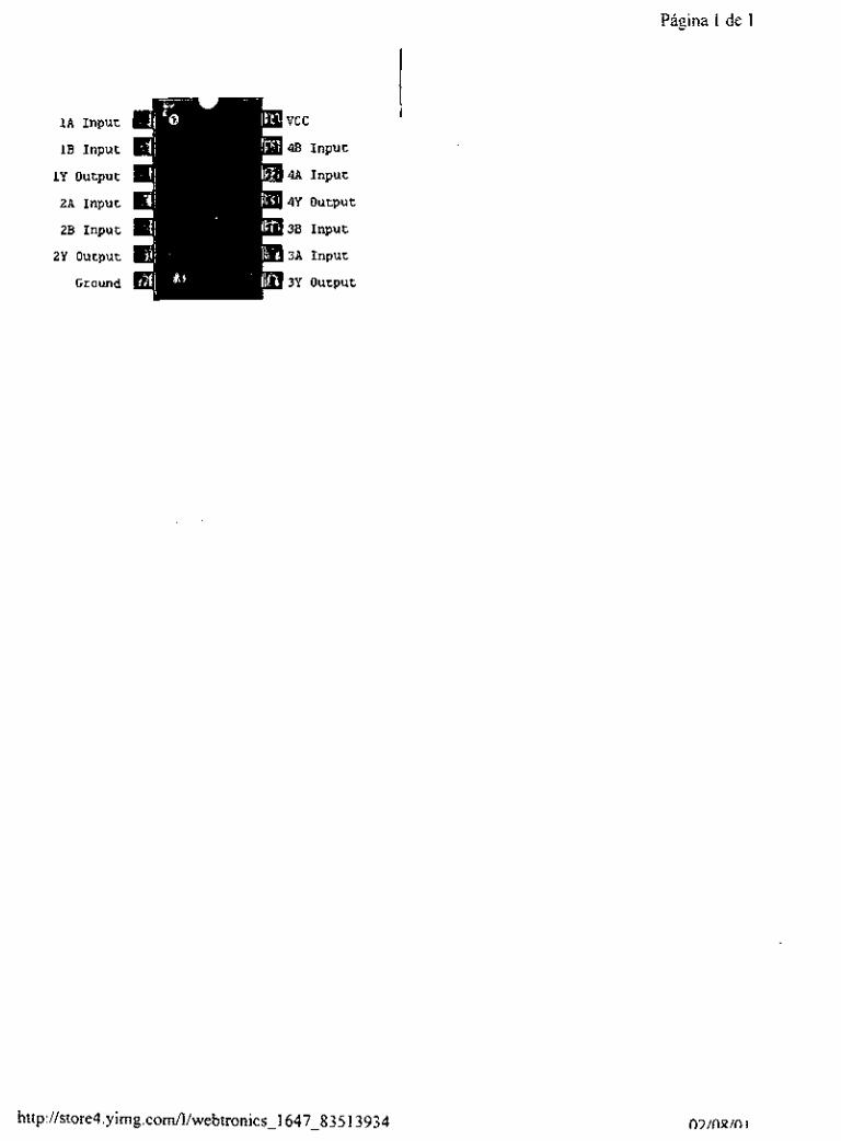
1A Input
1B Input
1Y output
2A input
2B Input
2 Y output
Ground
http://store4.yimg.com/l/webtronics~i 647-835 13934
Página 1 de 1

74LS240 - Octal Inv Bus Ln Drvr Página 1 de 1
0 Circuit Specialists IOuE.aDz
74L.5240 - Octal Inv Bus Ln Drvr
74LS240 I+ 1 oo+
á0.45ea. á0.35ea
F O a q f*, .. .._ ..
.... Circuit Specialists Inc . . . . 220 South Country Club Drive #2 Mesa, Az 85210 800-528-1417
http://store.yahoo.com/webtronics/ls240. html

Página 1 de 1
1G Enable
1Al Input
2Y4 Output
1A2 Input
2Y3 Output
lA3 Input
2Y2 output
1A4 Input
2Y1 output
GND
http:~/store4.yimg.com/I/webtronics 1647 87979442

. . . . , , ;;. . . . . . I '
. . . . ) ... ..... . . . . . . . . . . . . . .< .~ , ~.
.. . . .
-_ - .. . . . . . ..............
. .
. . .- . . ,
.
j , , .
. . - I
. .

74LSOO description
74LSOO - Quadruple 2-Input Positive NAND Gates
[Inputs] pqq Logic:
Y=(AB)’
Y=A‘+B’ nu E 3 [77[17 FCl
Chip Layout
II 74LSOO
1 A
lE
1Y
2A
28
2 Y
GND
vcc
4 6
4A
4Y
3 8
3A
3Y
Chip Pin Assignmen
power: pin 14
ground: pin 7
Página 1 de 1

APÉNDICE c COTIZACIONES
132

Mésico D. F. a 25 de octubre de 2000
Centro Nacional de Actualización Docente Estanisiao Ramirez esquina Mar de las Lluvias Col Selene Delegación Tlahuac.
Con atención a: Integrantes de la 9" generacion del area de máquinas
Ponemos a su consideración la presente c.otización del siguiente material:
Cantidad 300 1 O0
1 O0
I O0
37
300 300 5 5 8
70
5
5 5 1 O0
Descripción precio unitario totales Tornillos allen de 3/16"xl/?", NF ..................................... 0.55 165.0Q. Tornilios allen de cabeza plana de 3 / l 6 s % NF .... ............................................................ 0.6- .............. 62JN Tomillos alien d c tuerca y arandela de presión ........................................... 0.78 Tornillos de cabeza hexagonal de 3x 25 mm cítuerca Tomillos de cabeza hexagonal de !;" x %", NC cituerca y
..........
.> 7
.....
.... ............................. .0.75
arandela de presión ...................................... .................. ,0.49.. ........... .13.90. Arandelas planas de 5 mm. ................... 0.1.5 ............... 4.5..0.0.. Arandelas presión de 5 mm ........................... ................ 0.03... ............. Iy,,o.o. Machuelos rosca 3/16" NF ... .................................. .30.00.. ...... Machueios rosca %" NF ........ .............. ;5..aa ....... rornilios de cabeza hexagonal de 511 6"x 'A" NC, con arandela de presion ................ ......................................... ........... .0..5,0.. ............ ..4..QO. Tornillos de cabeza hesagonai 3/8"x %" con tuerca cuadrada Y arandela de presión ............ Llaves allen para tomillos de cabeza plana ...................................................................... 2 Llaves alien para tomillos de %" ....................................... 3,.89 i9,.45 Llaves allen para tornillos de 3/16'. ................................... 3.11 lS.SS:. . . Arandelas de tapicero ............ ..................................... N . o . h s . m a n e j ~ ~ s . . ..
. .
.................................... 0.9.8.. .............. I9,00.
............. ....
............
CASA DEL TORNILLO VERT pmOVEEDOWI DE ,ORN,,,OS RFC: R1ES-190824F59 Dr V6mZ 425 Coi. Buenos Aires
DOCTOR VERTLZ No. 425 tei: 55387171 Mexico D.F. OCT. 26 2000
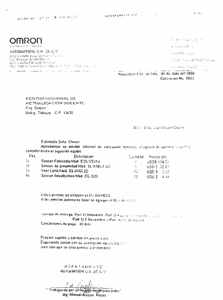
omraon
.., . . . . . ~ . .. . . ._.^, I , - _ .; Coiizacion No. @O05
Esliniada Srita. ChaJt: Aleiidiendo su amable :obci!ub de CoicacInri ienenxx i.l s p r z d c d;- io::e:e: .( si! fi~,:
consideracion el siguiente equipo: Descripciori Cjri! if?2d Precio Vnl .
1 ) Sensor Foiocelda hbd. EJS.VSiF.4 1, %!IS 170::.' 1JC.D 3 -7 - I
5 ) Inter Limil Mod. SS-OIGLZD C,5 USD S 7.17
P O S .
2! Sensor de prorimidad M a d . TL-XlüCi -GL ,,.t.:..
5 ; Sensor fotoeleclrico Mod. EE.SS5 . L L'su 9 L . L ¿ i( _.
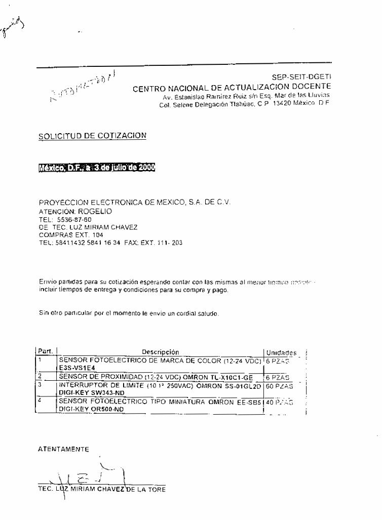
SEP-SEIT-DGETI CENTRO NACIONAL DE ACTUALIZACION DOCENTE
Av. Esianislao Rainirez Ruiz s h Esq. Mar de las Lliivi:?s. Col. Selene Delegación Tlahúac, C P 13420 Mexico D F
- - 1 ; i) r J . . , ;.,, :j<> ¡'I I - i'
Descripción SENSOR FOTOELECTRICO DE MARCA DE COLOR (12-24 VDC) E3S -VS1 E4 SENSOR DE PROXIMIDAD (12-24 VDC) OMRON TL-XlOC1-GE INTERRUPTOR DE LIMITE (10.1' 25OVAC) OMRON SS-OlGLZD DIGI-KEY SW343-ND SENSOR FOTOELECTRICO TIPO MINIATURA OMRON EE-SB5 DIGI-KEY OR500-ND -
SOLICITUD DE COTlZAClON
Unidades 6 PZ..iS ~. .
6 P2A.s~ 1 60 PZAS-~..
40 PLI-5 i
..
i
PROYECCION ELECTRONICA DE MEXICO, SA DE C V ATENCION ROGELIO TEL 5536-87-60 DE TEC LUZ MIRIAM CHAVEZ COMPRAS EXT 104 TEL 58411432 5841 16 34 FAX EXT 111- 203
Envio parlidas para su cotización esperando conlar con las mismas al nieiior IIcinix! :!??,:>!? incliiir tiempos de entrega y condiciones para su compra y pago.
Sin otro particular por el momento le envio u n cordial saludo
E ATENTAMENTE
- :
MIRIAM C H A V E Z ~ E LA TORE

Reparaciones Ruíz Nazario Ruiz Skewes
RFC: RUSN 29091 I 3G6 Calle Sur 125 A No. 60, Col.
Sta. Isabel Industrial iztapaiapa, Mexico, D. F.
Tel: 55815070
México. D. f. a 6 de noviembre del 2000
CENTRO NACIONAL DE ACTUALIZACION DOCENTE Estanislao Ramirez Ruiz. esquina con Mar de las Lluvias Col. Selene, Delegaci6n Tlahuac. 13420, Mexico, D. F. Tels: 5841 1432 / Fax: 5841 1634
Con atención a los integrantes de la iX Generación de Mecatronica, área de Maquinas.
En respuesta a su solicitud de cotizaci6n, se dan a conocer los siguientes precios del material y servicios que se pidieron:
Cantidad Unidades Descripción
o1 kg Soldadura de bronce de 1/8"
o1 bote Fundente para soldadura de bronce
Llenado de tanque de oxigeno para soldar
Precios unitarios
$70.00
$15.00
$60.00
Nota: Precios no incluyen IVA
ATENTAMENTE:
NRZARIO RUIZ S. PROPIETARIO
REPARACIONES Y VENTA DE EQUIPOS PARA SOLDADURA AWOGENA, GASES Y OXiGENO MEDICINAL. FABRICACION DE MANIFOLDS Y CONEATONES

CARPENTER @ Aceros Fortuna
ACEROS FORTUNA, S. A. DE C.V. COSECHADORES No. 33, COL. EX HACIENDA STA. ISABEL IZTAPALAPA, MEXICO, D. F. FAX 56702208
México. D. F. a 3 de noviembre del 2000
SECRETARIA DE EDUCACION PUBLICA CENTRO NACIONAL DE ACTUALIZACION DOCENTE Estanisiao Ramirez Ruiz. esquina con Mar de las Lluvias Col. Selene. Delegacibn Tlahuac. 13420, Mexico, D. F. Tels: 5841 1432 I Fax: 5841 1634
Con atención a los integrantes de la IX Generación de Mecatronica, Area de Maquinas.
En respuesta a la solicitud de cotización del presente material, damos a conocer los siguientes precios que actualmente estamos ofreciendo al publico en general, esperando contar con su preferencia:
Clave Cantidad Unidades Piezas Descripcibn 5 unitario x kgm Importe
1 o9 3.800 kg O2 Barra redonda de bronce $40.19 $152.72 estaridar de 1" de diam.
Nota Importante: Nuestros precios no incluyen IVA
ATENTAMENTE:
ACEROS FORTUNA I IZTAPALAPA
J. F. ORTiZ G. VENTAS

DISTRIBUIDORA DE TORNILLOS
RFC: VARF 550305 KC9 Ave. Tlahuac No. 5755, Local C
Col. Sta. Ana ZaDotiUan .~ ~~~
13300 Deleg. Tlahuac,'Mexico. D. F. Tels: 58630192 y 58639987
M&xico, D. F. a 30 de octubre de 2000
SEP SElT DGETI CENTRO NACIONAL DE ACTUALIZACION DOCENTE Estanislao Ramirez Ruiz. sin Col. Seiene. Delegación Tlahuac. 13420, Mexico, D. F. Tels: 58411432 I Fax: 58411634
Con atencion a los intearantes de la IX Generación de Mecatronica. area de Maauinas.
Cotización de tornilleria y accesorios solicitados:
Cant. Descripción $ Importe Total $68.00
$15.00
$6.00
$60.00
TOTAL: $149.00
20
20
05
150
Seguros de arillo exterior de 22.2 mm (Candados TRU ARC)
Tornillos de cabeza hexagonal completos de 6.4 mrn x 31.7 mm
Tornillos de cabeza hexagonal drond plana y presion 9.5 mrn x 19.0 mrn
Tornillos de cabeza filips dtuerca hexagonal de 2.9 mm x 9.5 mm
Nola: Precios sin NA
Federico A. Valdés R
tornisiir
MAYWE0 Y MENUDEO DE UN EXENSO SURTIOO EN TORNILLOS. WEWS. BIRLM. WAS PARA MüUxIRA5. HERRAnIENiAS EN GENW.FABRICACION ESPECIAL DE TORNILLERIA SDBE PEDIOO.

9 BlBLlOGRAFíA
1. GIECK, KURT. Manual de fórmulas técnicas. Ediciones Alfaomega, l g a edición, México 1998.
2 MORING FAIRES VIRGIL Diseiío de elementos de maquinas, Editorial Limusa, cuarta reimpresión, México 1994,783~
3 HANDS APPOLD, et al. Tecnología de los metales para profesiones Editorial Reverté S. A.
F. RILEY WlLlAM Y D. STURGES LEROY. lnqenieria Mecánica Dinámica, Editorial Reverté S. A.
5 VENTON LEVY DOUGHTIE WALTER H. JAMES. Elementos de mecanísmos. Editorial Cecsa, 8a edición, Pais México año 1996,pag 383- 390.A.
4
6 Catálogo de productos /KO. IKO bearings. Ca tálogo-5906
7 Catálogo de bandas de transmisión CHlORlNO S.p. A. Cía. Industrial Biella, S. A. de C. V.
México D.F.
8 Catálogo de productos SMC
9 Catálogo de motores 1999-2000
10 Catálogo de Neumática FESTO
SMC Corporation México, S.A. de C. V.
Servo system 0.
11 Omron’s product catalogs
12 www.omron.com
13 www. Festo.com
14 www. questlink.com
15 www. googIe.com 0 1 - 0 5 3 4
133
Top Related