Otdr Prolite 50-51-52
110
PROLITE-50/51/52 REFLECTÓMETRO ÓPTICO (OTDR) OPTICAL REFLECTOMETER (OTDR) - 0 MI1858 -
-
Upload
sergio-ariasgago -
Category
Documents
-
view
20 -
download
0
Transcript of Otdr Prolite 50-51-52
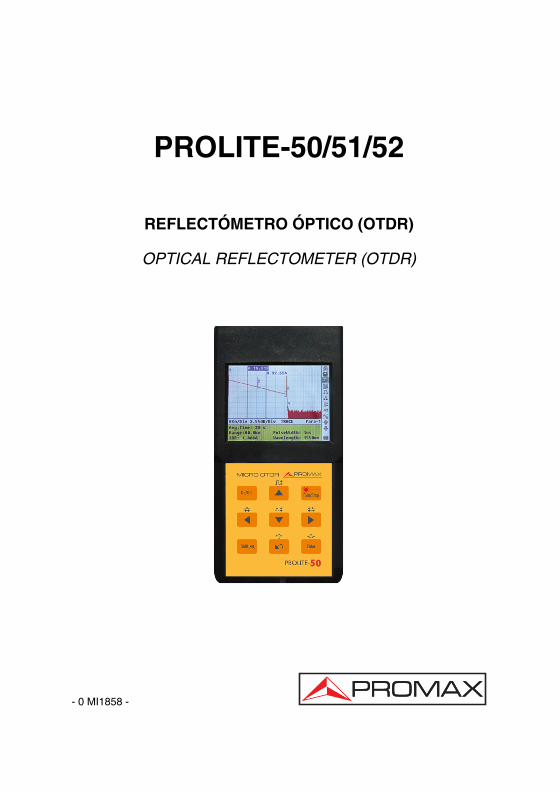
PROLITE-50/51/52
REFLECTÓMETRO ÓPTICO (OTDR)
OPTICAL REFLECTOMETER (OTDR)
- 0 MI1858 -

NOTAS SOBRE SEGURIDAD Antes de manipular el equipo leer el manual de instrucciones y muy especialmente el apartado PRESCRIPCIONES DE SEGURIDAD.
El símbolo sobre el equipo significa "CONSULTAR EL MANUAL DE INSTRUCCIONES". En este manual puede aparecer también como símbolo de advertencia o precaución. Recuadros de ADVERTENCIAS Y PRECAUCIONES pueden aparecer a lo largo de este manual para evitar riesgos de accidentes a personas o daños al equipo u otras propiedades.
SAFETY NOTES Read the user’s manual before using the equipment, mainly " SAFETY RULES " paragraph.
The symbol on the equipment means "SEE USER’S MANUAL". In this manual may also appear as a Caution or Warning symbol. Warning and Caution statements may appear in this manual to avoid injury hazard or damage to this product or other property.

SUMARIO CONTENTS
Manual español................................................................................ English manual ................................................................................
Eng
lish

MANUAL DE INSTRUCCIONES. PROLITE-50/51/52
Í N D I C E 1. GENERAL.................................................................................................................. 1
1.1 Especificaciones.................................................................................................. 3 2. PRESCRIPCIONES DE SEGURIDAD ...................................................................... 5
2.1 Generales............................................................................................................ 5 2.2 Precauciones Específicas ................................................................................... 5 2.3 Ejemplos Descriptivos de las Categorías de Sobretensión ................................ 6
3. DESCRIPCIÓN DE MANDOS Y ELEMENTOS ........................................................ 7 3.1 Panel de conexiones. .......................................................................................... 7 3.2 Teclado de funciones. ......................................................................................... 8
4. INFORMACIÓN BÁSICA DEL PROLITE-50/51/52 ................................................. 10 4.1 Principio de funcionamiento del PROLITE-50/51/52......................................... 10 4.2 Definición básica y clasificación de los eventos................................................ 10
4.2.1 Eventos ....................................................................................................... 10 4.2.1.1 Eventos de reflexión ............................................................................. 11 4.2.1.2 Eventos de no reflexión. ....................................................................... 11 4.2.1.3 Inspección de eventos.......................................................................... 12
4.3 Aplicación de las medidas del PROLITE-50/51/52 ........................................... 12 4.3.1 Contenidos de medida del PROLITE-50/51/52........................................... 12 4.3.2 Análisis de trazas del PROLITE-50/51/52 .................................................. 12
4.4 Pantalla de visualización de trazas del PROLITE-50/51/52.............................. 13 4.4.1 Pantalla de trazas del PROLITE-50/51/52.................................................. 13 4.4.2 Ventana de información del PROLITE-50/51/52......................................... 14
4.4.2.1 Parámetros de Traza de Medidas ........................................................ 14 4.4.2.2 Lista de eventos ................................................................................... 15 4.4.2.3 Precisión............................................................................................... 16
5. PROCESO DE MEDIDA DE TRAZAS..................................................................... 17 5.1 Introducción a la Interficie Gráfica de Usuario (GUI)......................................... 17
5.1.1 Barra de menú del PROLITE-50/51/52....................................................... 18 5.1.2 Estado de carga de la batería..................................................................... 18
5.2 Proceso de medida ........................................................................................... 19 5.2.1 Configuración de parámetros en la barra de menú del PROLITE-50/51/52.. 20 5.2.2 Medida de la traza - Auto............................................................................ 36 5.2.3 Medida de trazas - Manual ......................................................................... 38 5.2.4 Medida de trazas — Motivos de errores en las medi das ............................ 39
5.3 Ventana de información. ................................................................................... 39 5.3.1 Conmutar entre los ítem de la ventana de información. ............................. 39 5.3.2 Repaso de la Lista de Eventos ................................................................... 39 5.3.3 Cursores ..................................................................................................... 40
5.4 Aumento y disminución de la visualización de la traza ..................................... 40 5.5 Guardar traza .................................................................................................... 41 5.6 Visualización de trazas guardadas.................................................................... 42 5.7 Descarga de las trazas guardadas al PC.......................................................... 43

MANUAL DE INSTRUCCIONES. PROLITE-50/51/52
6. MANTENIMIENTO................................................................................................... 44
6.1 Mantenimiento de las baterías .......................................................................... 44 6.2 Limpieza de las interfaces................................................................................. 45 6.3 Requerimientos de calibración .......................................................................... 48 6.4 Recomendaciones de limpieza ......................................................................... 48
MANUAL DE INSTRUCCIONES. PROLITE-50/51/52
07-2011 Página 1
REFLECTÓMETRO ÓPTICO (OTDR) PROLITE-50/51/52
1. GENERAL
La serie PROLITE-50/51/52 de PROMAX es la elección recomendada para la medida de las especificaciones de fibras ópticas. Con el PROLITE-50/51/52, puede realizar el análisis de una única fibra óptica o de una instalación de fibras completa. En especial, permite valorar las pérdidas y la distribución de los fenómenos en una instalación de fibra óptica.
La serie PROLITE-50/51/52 de PROMAX comprueba la calidad de la transmisión de la fibra óptica mediante la medida de la dispersión de luz de retorno. Organizaciones de normalización internacional como la Unión Internacional de Telecomunicaciones (ITU) define la dispersión de luz como un procedimiento efectivo para la medida de las pérdidas en fibras ópticas. La dispersión de retorno es también el único modo efectivo de inspeccionar conectores, aplicable también a la medida de la longitud de las fibras ópticas.
Por tanto, el PROLITE-50/51/52 es una herramienta muy útil para la fabricación de fibras ópticas, su instalación y mantenimiento.
El principio de funcionamiento del PROLITE-50/51/52 consiste en revisar los “fenómenos” que se producen en las fibras ópticas (por ejemplo, las irregularidades y los conectores), lo que resulta muy útil para el control de calidad por parte de los fabricantes, instaladores y técnicos de mantenimiento de las fibras ópticas. El PROLITE-50/51/52 puede ayudar a identificar las irregularidades en las fibras ópticas, localizarlas y medir su atenuación, pérdidas relevantes y homogenidad.
El PROLITE-50/51/52 es más útil para trabajos de campo. Puede ayudar a comprobar la idoneidad de un circuito basado en instalaciones de fibra óptica. Con el objeto de realizar futuros mantenimientos y controles de calidad de las transmisiones es necesario registrar las características de las fibras ópticas, que incluyen la medida del trayecto óptico, las pérdidas totales y las pérdidas en los empalmes y los conectores.
Además, el PROLITE-50/51/52 es fácil de utilizar, pequeño y compacto. Siguiendo los principios de la ergonomía, se ha diseñado para satisfacer los requisitos del usuario con una gran pantalla LCD e interfaz gráfica. Permite guardar y transferir los datos medidos de las gráficas de características a un PC mediante el software suministrado para su análisis posterior, informe e impresión.
MANUAL DE INSTRUCCIONES. PROLITE-50/51/52
Página 2 07-2011
Los PROLITE-50/51/52 se caracterizan por:
• Aplicaciones básicas:
a) Medida de la longitud de la fibra óptica.
b) Medida de la distancia entre dos puntos de la fibra.
c) Localización de fallos y discontinuidades en fibras ópticas.
d) Representación de la curva de distribución para fibras ópticas.
e) Medida del coeficiente de atenuación de fibras ópticas.
f) Medida de las pérdidas entre dos puntos de la fibra óptica.
g) Medida de las pérdidas en los empalmes.
h) Medida de los fenómenos de reflexión de fibras ópticas.
Para un evento específico (variación en la calidad de transmisión debido a fallos
causados por uniones, conectores, curvaturas, etc). las siguientes medidas pueden ser realizadas con el PROLITE-50/51/52:
a) Para cada evento: distancia, pérdidas y reflexiones;
b) Para cada sección de la fibra óptica: longitud y pérdidas en dB o dB/km;
c) Para la cadena completa de fibra óptica: longitud y pérdidas en dB;
• Pantalla LCD de gran formato con ajuste manual del contraste
• Pantalla LCD retroiluminada para uso nocturno
• Facilidad de uso con pantalla de representación gráfica
• Función de almacenamiento de trazas
• Puerto de carga de datos RS232/USB
• Software de análisis mediante PC y gestión de trazas para analizar y transmitir los datos previamente almacenados.
• Función de autodesconexión para ahorro de la vida de las baterías
• Alimentador AC.
MANUAL DE INSTRUCCIONES. PROLITE-50/51/52
07-2011 Página 3
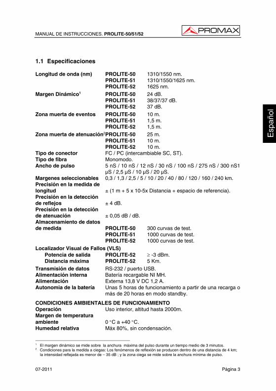
1.1 Especificaciones Longitud de onda (nm) PROLITE-50 1310/1550 nm. PROLITE-51 1310/1550/1625 nm. PROLITE-52 1625 nm. Margen Dinámico1 PROLITE-50 24 dB. PROLITE-51 38/37/37 dB. PROLITE-52 37 dB. Zona muerta de eventos PROLITE-50 10 m. PROLITE-51 1,5 m. PROLITE-52 1,5 m. Zona muerta de atenuación2PROLITE-50 25 m. PROLITE-51 10 m. PROLITE-52 10 m. Tipo de conector FC / PC (intercambiable SC, ST). Tipo de fibra Monomodo. Ancho de pulso 5 nS / 10 nS / 12 nS / 30 nS / 100 nS / 275 nS / 300 nS1
µS / 2,5 µS / 10 µS / 20 µS. Margenes seleccionables 0,3 / 1,3 / 2,5 / 5 / 10 / 20 / 40 / 80 / 120 / 160 / 240 km. Precisión en la medida de longitud ± (1 m + 5 x 10⁻⁵x Distancia + espacio de referencia). Precisión en la detección de reflejos ± 4 dB. Precisión en la detección de atenuación ± 0,05 dB / dB. Almacenamiento de datos de medida PROLITE-50 300 curvas de test. PROLITE-51 1000 curvas de test. PROLITE-52 1000 curvas de test. Localizador Visual de Fallos (VLS) Potencia de salida PROLITE-52 ≥ -3 dBm. Distancia máxima PROLITE-52 5 Km. Transmisión de datos RS-232 / puerto USB. Alimentación interna Batería recargable NI MH. Alimentación Externa 13,8 V DC 1,2 A. Autonomia de la batería Unas 5 horas de funcionamiento a partir de una recarga o
más de 20 horas en modo standby.
CONDICIONES AMBIENTALES DE FUNCIONAMIENTO Operación Uso interior, altitud hasta 2000m. Margen de temperatura ambiente 0 °C a +40 °C. Humedad relativa Máx 80%, sin condensación.
1 El margen dinámico se mide sobre la anchura máxima del pulso durante un tiempo medio de 3 minutos. 2 Condiciones para la medida a ciegas: Los fenómenos de reflexión se producen dentro de una distancia de 4 km;
la intensidad reflejada es menor de — 35 dB ; y la zona ciega se mide sobre la anchura mínima de pulso.
MANUAL DE INSTRUCCIONES. PROLITE-50/51/52
Página 4 07-2011
CARACTERÍSTICAS MECÁNICAS Dimensiones 220 (Al) x 110 (An) x 70 (Pr) mm. Peso 1 kgs.
ACCESORIOS AL005 Alimentador AC 100V/240V 50/60 Hz.
Bolsa de transporte.
0 MI1858 Manual de instrucciones.
CD con software de comunicación.
Cable comunicación con PC.
AD500 Adaptador ST (Opcional).
AD502 Adaptador SC (opcional).
RECOMENDACIONES ACERCA DEL EMBALAJE
Se recomienda guardar todo el material de embalaje de forma permanente por si fuera necesario retornar el equipo al Servicio de Asistencia Técnica.
MANUAL DE INSTRUCCIONES. PROLITE-50/51/52
07-2011 Página 5
2. PRESCRIPCIONES DE SEGURIDAD 2.1 Generales
* La seguridad puede verse comprometida si no se aplican las instrucciones dadas en este Manual.
* Este equipo puede ser utilizado en ambientes con Grado de Polución 1.
* Al emplear cualquiera de los siguientes accesorios debe hacerse sólo con los tipos especificados a fin de preservar la seguridad:
Alimentador AL-005.
Batería del relog.
* Tener siempre en cuenta los márgenes especificados tanto para la alimentación como para la medida.
* Recuerde que las tensiones superiores a 70 V DC ó 33 V AC rms son potencialmente peligrosas.
* Observar en todo momento las condiciones ambientales máximas especificadas para el aparato.
* El operador no está autorizado a intervenir en el interior del equipo:
Cualquier cambio en el equipo deberá ser efectuado exclusivamente por personal especializado.
* Seguir estrictamente las recomendaciones de limpieza que se describen en el apartado Mantenimiento.
2.2 Precauciones Específicas
PRECAUCIÓN Se recomienda no mirar directamente al haz. La utilización de dispositivos que no sean los especificados en este manual así como la manipulación interna del equipo pueden ser causa de radiación peligrosa.
MANUAL DE INSTRUCCIONES. PROLITE-50/51/52
Página 6 07-2011
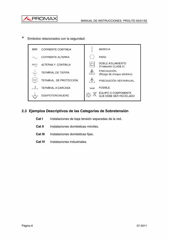
* Símbolos relacionados con la seguridad:
2.3 Ejemplos Descriptivos de las Categorías de Sobretensión
Cat I Instalaciones de baja tensión separadas de la red.
Cat II Instalaciones domésticas móviles.
Cat III Instalaciones domésticas fijas.
Cat IV Instalaciones industriales.
MANUAL DE INSTRUCCIONES. PROLITE-50/51/52
07-2011 Página 7
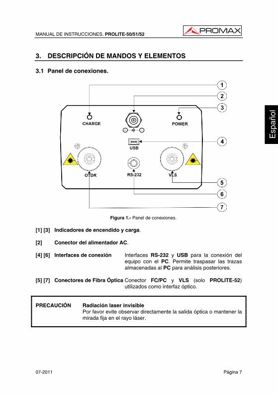
3. DESCRIPCIÓN DE MANDOS Y ELEMENTOS 3.1 Panel de conexiones.
Figura 1.- Panel de conexiones. [1] [3] Indicadores de encendido y carga. [2] Conector del alimentador AC. [4] [6] Interfaces de conexión Interfaces RS-232 y USB para la conexión del
equipo con el PC. Permite traspasar las trazas almacenadas al PC para análisis posteriores.
[5] [7] Conectores de Fibra Óptica Conector FC/PC y VLS (solo PROLITE-52)
utilizados como interfaz óptico.
PRECAUCIÓN Radiación laser invisible Por favor evite observar directamente la salida óptica o mantener la
mirada fija en el rayo láser.
MANUAL DE INSTRUCCIONES. PROLITE-50/51/52
Página 8 07-2011
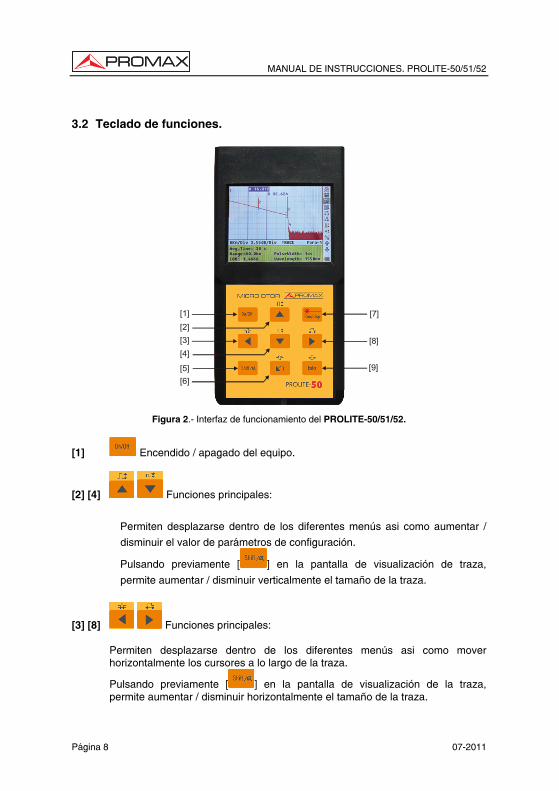
3.2 Teclado de funciones.
[1][2][3][4]
[5][6]
[7]
[8]
[9]
Figura 2.- Interfaz de funcionamiento del PROLITE-50/51/52.
[1] Encendido / apagado del equipo.
[2] [4] Funciones principales:
Permiten desplazarse dentro de los diferentes menús asi como aumentar /
disminuir el valor de parámetros de configuración.
Pulsando previamente [ ] en la pantalla de visualización de traza,
permite aumentar / disminuir verticalmente el tamaño de la traza.
[3] [8] Funciones principales:
Permiten desplazarse dentro de los diferentes menús asi como mover horizontalmente los cursores a lo largo de la traza.
Pulsando previamente [ ] en la pantalla de visualización de la traza, permite aumentar / disminuir horizontalmente el tamaño de la traza.
MANUAL DE INSTRUCCIONES. PROLITE-50/51/52
07-2011 Página 9
[5] Pulsándolo previamente permite ejecutar las funciones secundarias. También sirve para cancelar las acciones de aumento / disminución de la visualización de traza que se haya realizado.
[6] Funciones principales:
Esta tecla permite pasar las páginas de la Ayuda, cancelar la operación
seleccionada, salir del menu de configuración y conmutar entre las ventanas de información de la traza visualizada.
Pulsando previamente [ ] permite revisar los eventos de traza anteriores.
[7] Tecla para iniciar / parar el proceso de medida.
[9] Pulsar esta tecla para confirmar la operación seleccionada.
Pulsando previamente [ ] permite revisar los eventos de traza posteriores.
MANUAL DE INSTRUCCIONES. PROLITE-50/51/52
Página 10 07-2011
4. INFORMACIÓN BÁSICA DEL PROLITE-50/51/52 4.1 Principio de funcionamiento del PROLITE-50/51/52
OTDR (Reflectómetro óptico en el dominio del tiempo) es un instrumento de medida para identificación de las características de la transmisión por fibra óptica. El instrumento se utiliza principalmente para medir la atenuación de una cadena completa de fibra óptica y proporcionar detalles de la atenuación relativos a la longitud, detección, localización y medida de cualquier fenómeno en la cadena de fibra óptica (los eventos se refieren a fallos provocados por uniones, conectores, y curvaturas cuyos cambios en la transmisión pueden medirse). Su conexión no destructiva del extremo para mediciones rápidas convierte al PROLITE-50/51/52 en una herramienta indispensable para la fabricación, construcción y mantenimiento de fibras ópticas.
Los fallos y la misma heterogeneidad de la fibra óptica puede provocar una dispersión de Rayleigh sobre los pulsos de luz transmitidos por la fibra óptica. Una parte de los pulsos de luz se dispersan en la dirección contraria lo que se conoce como dispersión de retorno de Rayleigh, lo que proporciona información válida a cerca de la atenuación en función de la longitud.
La información relativa a la distancia se obtiene a partir de la información del tiempo (de ahí la denominación “en el dominio del tiempo” en las siglas OTDR). Se produce una reflexión de Fresnel en la frontera entre dos medios con diferente IOR (por ejemplo, conexiones inadecuadas, conectores o el extremo de la fibra óptica). Esta reflexión se utiliza para localizar los puntos de discontinuidad en una fibra óptica. La magnitud de la reflexión depende de las diferencias entre IOR y lo abrupto que resulte la frontera.
El OTDR transmite un pulso de luz por la fibra óptica conectada, y recibe las reflexiones de los eventos así como la potencia de la dispersión de retorno del pulso en el tiempo. El lugar geométrico se mostrará en el LCD. El eje Y corresponde a los valores de potencia de la dispersión de retorno expresada en dB, y el eje X corresponde a la distancia. 4.2 Definición básica y clasificación de los eventos 4.2.1 Eventos
Los eventos indican puntos anormales que provocan atenuación o cambio súbito de la potencia de dispersión aparte de la dispersión habitual de la fibra óptica, lo que incluye todos los tipos de pérdidas como las curvaturas, conexiones y discontinuidades. Los puntos correspondientes a los eventos que aparecen indicados en el LCD son puntos anormales que provocan que las trazas se desvíen de su trayectoria en línea recta.
MANUAL DE INSTRUCCIONES. PROLITE-50/51/52
07-2011 Página 11
Los eventos pueden clasificarse como eventos de reflexión y eventos de no
reflexión. 4.2.1.1 Eventos de reflexión
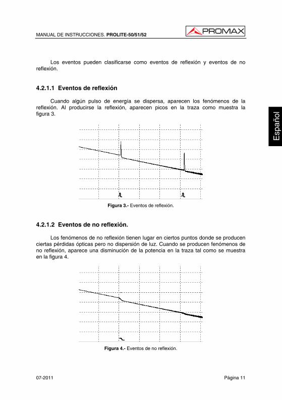
Cuando algún pulso de energía se dispersa, aparecen los fenómenos de la reflexión. Al producirse la reflexión, aparecen picos en la traza como muestra la figura 3.
Figura 3.- Eventos de reflexión. 4.2.1.2 Eventos de no reflexión.
Los fenómenos de no reflexión tienen lugar en ciertos puntos donde se producen ciertas pérdidas ópticas pero no dispersión de luz. Cuando se producen fenómenos de no reflexión, aparece una disminución de la potencia en la traza tal como se muestra en la figura 4.
Figura 4.- Eventos de no reflexión.
MANUAL DE INSTRUCCIONES. PROLITE-50/51/52
Página 12 07-2011
4.2.1.3 Inspección de eventos
El PROLITE-50/51/52 transmite un pulso de luz en la fibra óptica a inspeccionar, y entonces recibe las señales de luz de retorno, comenzando a calcular la distancia del “evento”. Cuanto mayor es la distancia, mayor tiempo precisa la luz dispersada para llegar hasta el instrumento. La distancia del evento puede ser calculada de acuerdo con el tiempo que tarda en recibir las señales de los eventos.
A través de la inspección de las señales dispersadas, propiedades de la fibra óptica, conectores y empalmes pueden ser identificados. 4.3 Aplicación de las medidas del PROLITE-50/51/52
El PROLITE-50/51/52 muestra la potencia relativa a la distancia de las señales de retorno. Esta información puede utilizarse para identificar las principales propiedades de una instalación de fibra óptica. 4.3.1 Contenidos de medida del PROLITE-50/51/52
• Localización de eventos (distancia), final o ruptura de una instalación de fibra óptica.
• Coeficiente de atenuación de la fibra.
• Pérdida por un único evento (por ejemplo, un empalme óptico), o pérdida total desde el extremo superior hasta el final.
• Margen de un único evento como la reflexión en conectores (o grado de reflexión).
• Medida automática de la pérdida acumulada para un único evento. 4.3.2 Análisis de trazas del PROLITE-50/51/52
El análisis de trazas del PROLITE-50/51/52 es totalmente automático. Las trazas localizan:
• Eventos de reflexión de las conexiones y empalmes mecánicos.
• Eventos de no reflexión (habitualmente en las uniones de los empalmes).
• Extremo de la fibra óptica (A partir de la detección del primer evento de pérdida que sea mayor del valor umbral final, el final de la fibra óptica puede ser identificado).
• Lista de eventos: tipo de evento, pérdida, reflexión y distancia.
MANUAL DE INSTRUCCIONES. PROLITE-50/51/52
07-2011 Página 13
4.4 Pantalla de visualización de trazas del PROLITE-50/51/52
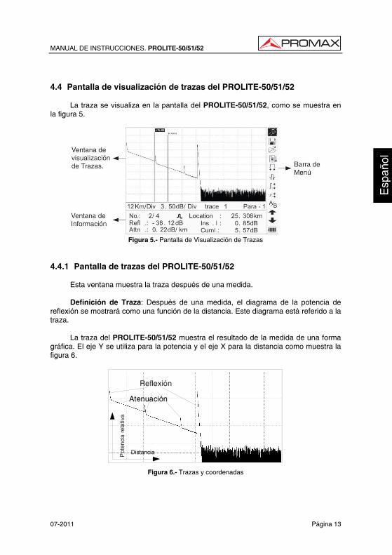
La traza se visualiza en la pantalla del PROLITE-50/51/52, como se muestra en la figura 5.
Figura 5.- Pantalla de Visualización de Trazas
4.4.1 Pantalla de trazas del PROLITE-50/51/52
Esta ventana muestra la traza después de una medida.
Definición de Traza: Después de una medida, el diagrama de la potencia de reflexión se mostrará como una función de la distancia. Este diagrama está referido a la traza.
La traza del PROLITE-50/51/52 muestra el resultado de la medida de una forma gráfica. El eje Y se utiliza para la potencia y el eje X para la distancia como muestra la figura 6.
Atenuación
Distancia
Reflexión
Pot
enci
a re
lativ
a
Figura 6.- Trazas y coordenadas
MANUAL DE INSTRUCCIONES. PROLITE-50/51/52
Página 14 07-2011
4.4.2 Ventana de información del PROLITE-50/51/52.
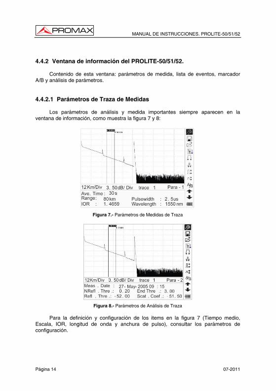
Contenido de esta ventana: parámetros de medida, lista de eventos, marcador A/B y análisis de parámetros. 4.4.2.1 Parámetros de Traza de Medidas
Los parámetros de análisis y medida importantes siempre aparecen en la ventana de información, como muestra la figura 7 y 8:
Figura 7.- Parámetros de Medidas de Traza
Figura 8.- Parámetros de Análisis de Traza
Para la definición y configuración de los items en la figura 7 (Tiempo medio,
Escala, IOR, longitud de onda y anchura de pulso), consultar los parámetros de configuración.
MANUAL DE INSTRUCCIONES. PROLITE-50/51/52
07-2011 Página 15
Para la definición de los items de la figura 8 (fecha, umbral de reflexión, umbral
de no reflexión, coeficiente de dispersión), por favor consultar los parámetros de configuración. 4.4.2.2 Lista de eventos
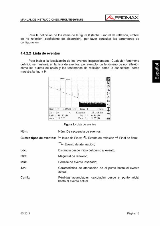
Para indicar la localización de los eventos inspeccionados. Cualquier fenómeno definido se mostrará en la lista de eventos, por ejemplo, un fenómeno de no reflexión como los puntos de unión y los fenómenos de reflexión como lo conectores, como muestra la figura 9.
Figura 9.- Lista de eventos Núm: Núm. De secuencia de eventos.
Cuatro tipos de eventos: Inicio de Fibra; Evento de reflexión Final de fibra;
Evento de atenuación;
Loc: Distancia desde inicio del punto al evento;
Refl: Magnitud de reflexión;
Insl: Pérdida de evento insertado;
Atn.: Característica de atenuación de el punto hasta el evento actual.
Cuml.: Pérdidas acumuladas, calculadas desde el punto inicial hasta el evento actual.
MANUAL DE INSTRUCCIONES. PROLITE-50/51/52
Página 16 07-2011
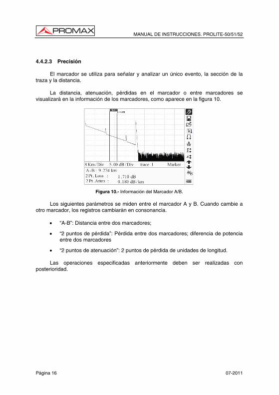
4.4.2.3 Precisión
El marcador se utiliza para señalar y analizar un único evento, la sección de la traza y la distancia.
La distancia, atenuación, pérdidas en el marcador o entre marcadores se visualizará en la información de los marcadores, como aparece en la figura 10.
Figura 10.- Información del Marcador A/B.
Los siguientes parámetros se miden entre el marcador A y B. Cuando cambie a otro marcador, los registros cambiarán en consonancia.
• “A-B”: Distancia entre dos marcadores;
• “2 puntos de pérdida”: Pérdida entre dos marcadores; diferencia de potencia entre dos marcadores
• “2 puntos de atenuación”: 2 puntos de pérdida de unidades de longitud.
Las operaciones especificadas anteriormente deben ser realizadas con posterioridad.
MANUAL DE INSTRUCCIONES. PROLITE-50/51/52
07-2011 Página 17
5. PROCESO DE MEDIDA DE TRAZAS Trazas 5.1 Introducción a la Interficie Gráfica de Usuario (GUI)
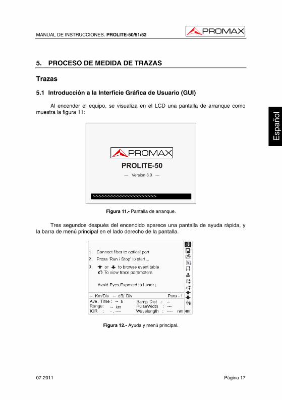
Al encender el equipo, se visualiza en el LCD una pantalla de arranque como muestra la figura 11:
ShinewayTechpal mOTDR- XXXX
- - - Ver si on 3. 0 - - -
>>>>>>>>>>>>>>>>>>>>>
PROLITE-50--- Versión 3.0 ---
Figura 11.- Pantalla de arranque.
Tres segundos después del encendido aparece una pantalla de ayuda rápida, y
la barra de menú principal en el lado derecho de la pantalla.
Figura 12.- Ayuda y menú principal.
MANUAL DE INSTRUCCIONES. PROLITE-50/51/52
Página 18 07-2011
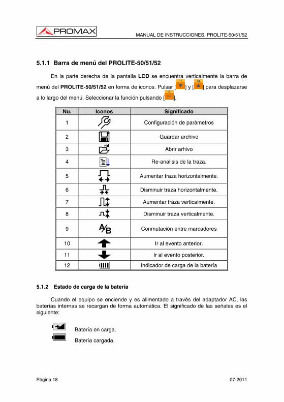
5.1.1 Barra de menú del PROLITE-50/51/52
En la parte derecha de la pantalla LCD se encuentra verticalmente la barra de
menú del PROLITE-50/51/52 en forma de iconos. Pulsar [ ] y [ ] para desplazarse
a lo largo del menú. Seleccionar la función pulsando [ ].
Nu. Iconos Significado
1
Configuración de parámetros
2
Guardar archivo
3
Abrir arhivo
4
Re-analisis de la traza.
5
Aumentar traza horizontalmente.
6
Disminuir traza horizontalmente.
7
Aumentar traza verticalmente.
8
Disminuir traza verticalmente.
9 BA
Conmutación entre marcadores
10
Ir al evento anterior.
11
Ir al evento posterior.
12 Indicador de carga de la batería
5.1.2 Estado de carga de la batería
Cuando el equipo se enciende y es alimentado a través del adaptador AC, las baterías internas se recargan de forma automática. El significado de las señales es el siguiente:
Batería en carga.
Batería cargada.
MANUAL DE INSTRUCCIONES. PROLITE-50/51/52
07-2011 Página 19
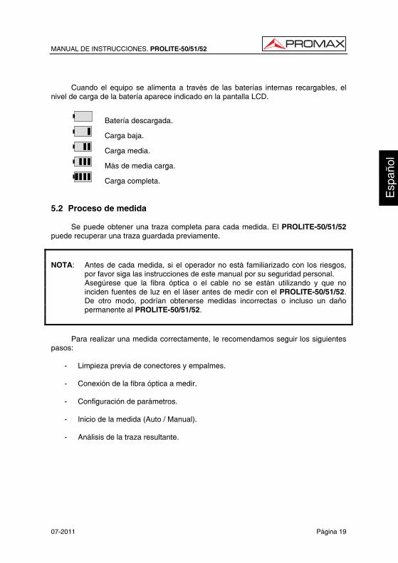
Cuando el equipo se alimenta a través de las baterías internas recargables, el
nivel de carga de la batería aparece indicado en la pantalla LCD.
Batería descargada.
Carga baja.
Carga media.
Más de media carga.
Carga completa. 5.2 Proceso de medida
Se puede obtener una traza completa para cada medida. El PROLITE-50/51/52 puede recuperar una traza guardada previamente.
NOTA: Antes de cada medida, si el operador no está familiarizado con los riesgos,
por favor siga las instrucciones de este manual por su seguridad personal. Asegúrese que la fibra óptica o el cable no se están utilizando y que no
inciden fuentes de luz en el láser antes de medir con el PROLITE-50/51/52. De otro modo, podrían obtenerse medidas incorrectas o incluso un daño permanente al PROLITE-50/51/52.
Para realizar una medida correctamente, le recomendamos seguir los siguientes
pasos:
- Limpieza previa de conectores y empalmes.
- Conexión de la fibra óptica a medir.
- Configuración de parámetros.
- Inicio de la medida (Auto / Manual).
- Análisis de la traza resultante.
MANUAL DE INSTRUCCIONES. PROLITE-50/51/52
Página 20 07-2011
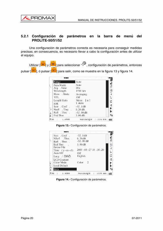
5.2.1 Configuración de parámetros en la barra de menú del
PROLITE-50/51/52
Una configuración de parámetros correcta es necesaria para conseguir medidas precisas; en consecuencia, es necesario llevar a cabo la configuración antes de utilizar el equipo.
Utilizar [ ] y [ ] para seleccionar , configuración de parámetros, entonces
pulsar [ ], ó pulsar [ ] para salir, como se muestra en la figura 13 y figura 14.
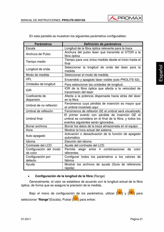
Figura 13.- Configuración de parámetros.
Figura 14.- Configuración de parámetros.
MANUAL DE INSTRUCCIONES. PROLITE-50/51/52
07-2011 Página 21
En esta pantalla se muestran los siguientes parámetros configurables:
Parámetros Definición de parámetros
Escala Longitud de la fibra óptica relevante para la traza
Anchura de Pulso Anchura del pulso láser que transmite el OTDR a la fibra óptica
Tiempo medio Tiempo para una única medida desde el inicio hasta el final
Longitud de onda Seleccionar la longitud de onda del láser para la medida
Modo de medida Seleccionar el modo de medida VFL Encendido y apagado láser visible (solo PROLITE-52). Unidades de longitud Para seleccionar las unidades de longitud.
IOR IOR de la fibra óptica que afecta a la velocidad de transmisión del láser
Coeficiente de dispersión
Afecta a la potencia dispersada hacia atrás del láser en la fibra
Umbral de no reflexión Fenómenos cuya pérdida de inserción es mayor que el umbral mostrado aquí
Umbral de reflexión Fenómenos de reflexión GE el umbral será visualizado
Umbral final El primer evento con pérdida de inserción GE el umbral se considera en el final de la fibra, y todos los eventos siguientes serán ignorados.
Borrar archivos Borrar los datos de la traza almacenada en el equipo Hora Mostrar la hora actual del sistema
Auto apagado Activación o desactivación de la función de apagado automático
Idioma Elección del idioma Contraste del LCD Ajuste del contraste del LCD Configuración del modo de color
Permite elegir entre 4 combinaciones de color diferentes
Configuración por defecto
Configurar todos los parámetros a los valores de fábrica
Ayuda Mostrar los archivos de ayuda (Guía de referencia rápida)
• Configuración de la longitud de la fibra (Range)
Generalmente, el valor se establece de acuerdo con la longitud actual de la fibra óptica, de forma que se asegure la precisión de la medida.
Bajo el menú de configuración de los parámetros, utilizar [ ] y [ ] para
seleccionar “Range”(Escala); Pulsar [ ] para entrar.
MANUAL DE INSTRUCCIONES. PROLITE-50/51/52
Página 22 07-2011
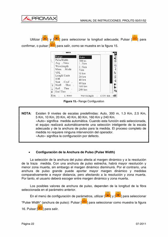
Utilizar [ ] y [ ] para seleccionar la longitud adecuada; Pulsar [ ] para
confirmar, o pulsar [ ] para salir, como se muestra en la figura 15.
Figura 15.- Range Configuration
NOTA: Existen 9 niveles de escalas predefinidas: Auto, 300 m, 1.3 Km, 2.5 Km,
5 Km, 10 Km, 20 Km, 40 Km, 80 Km, 160 Km y 240 Km. «Auto» significa medida automática. Cuando esta función está seleccionada,
el equipo realizará automáticamente una selección inteligente de la escala adecuada y de la anchura de pulso para la medida. El proceso completo de medida no requiere ninguna intervención del operador.
«Auto» significa la configuración por defecto.
• Configuración de la Anchura de Pulso (Pulse Width)
La selección de la anchura del pulso afecta al margen dinámico y a la resolución de la traza medida. Con una anchura de pulso estrecha, habrá mayor resolución y menor zona muerta, sin embargo el margen dinámico disminuirá. Por el contrario, una anchura de pulso grande puede aportar mayor margen dinámico y medidas comparativamente a mayor distancia, pero afectando a la resolución y zona muerta. Por tanto, el usuario deberá escoger entre margen dinámico y zona muerta.
Los posibles valores de anchura de pulso, dependen de la longitud de la fibra seleccionada en el parámetro anterior.
En el menú de configuración de parámetros, utilizar [ ] y [ ] para seleccionar
“Pulse Width” (anchura de pulso): Pulsar [ ] para seleccionar como muestra la figura
16. Pulsar [ ] para salir.
MANUAL DE INSTRUCCIONES. PROLITE-50/51/52
07-2011 Página 23
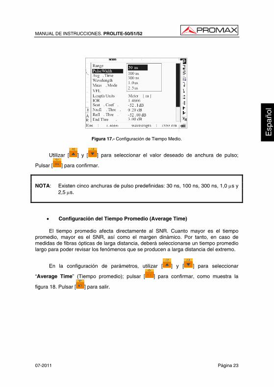
Figura 17.- Configuración de Tiempo Medio.
Utilizar [ ] y [ ] para seleccionar el valor deseado de anchura de pulso;
Pulsar [ ] para confirmar.
NOTA: Existen cinco anchuras de pulso predefinidas: 30 ns, 100 ns, 300 ns, 1,0 µs y
2,5 µs.
• Configuración del Tiempo Promedio (Average Time)
El tiempo promedio afecta directamente al SNR. Cuanto mayor es el tiempo promedio, mayor es el SNR, así como el margen dinámico. Por tanto, en caso de medidas de fibras ópticas de larga distancia, deberá seleccionarse un tiempo promedio largo para poder revisar los fenómenos que se producen a larga distancia del extremo.
En la configuración de parámetros, utilizar [ ] y [ ] para seleccionar
“Average Time” (Tiempo promedio); pulsar [ ] para confirmar, como muestra la
figura 18. Pulsar [ ] para salir.
MANUAL DE INSTRUCCIONES. PROLITE-50/51/52
Página 24 07-2011
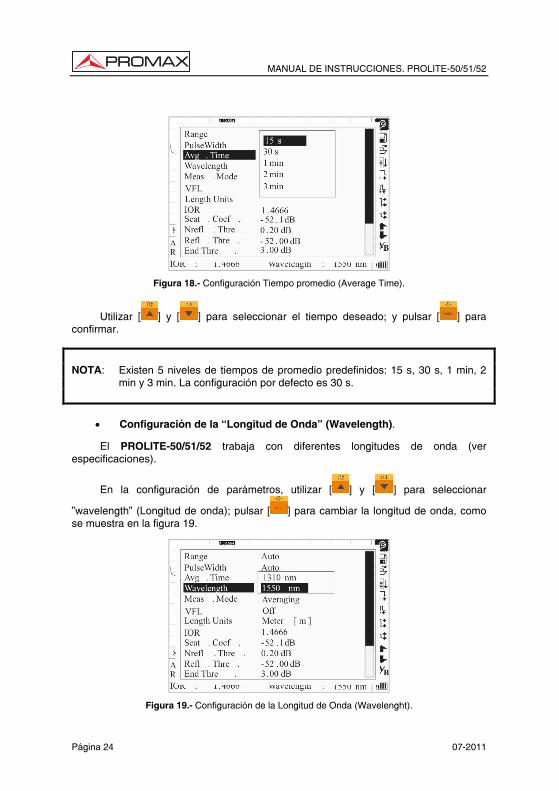
Figura 18.- Configuración Tiempo promedio (Average Time).
Utilizar [ ] y [ ] para seleccionar el tiempo deseado; y pulsar [ ] para confirmar.
NOTA: Existen 5 niveles de tiempos de promedio predefinidos: 15 s, 30 s, 1 min, 2
min y 3 min. La configuración por defecto es 30 s.
• Configuración de la “Longitud de Onda” (Wavelength).
El PROLITE-50/51/52 trabaja con diferentes longitudes de onda (ver especificaciones).
En la configuración de parámetros, utilizar [ ] y [ ] para seleccionar
”wavelength” (Longitud de onda); pulsar [ ] para cambiar la longitud de onda, como se muestra en la figura 19.
Figura 19.- Configuración de la Longitud de Onda (Wavelenght).
MANUAL DE INSTRUCCIONES. PROLITE-50/51/52
07-2011 Página 25
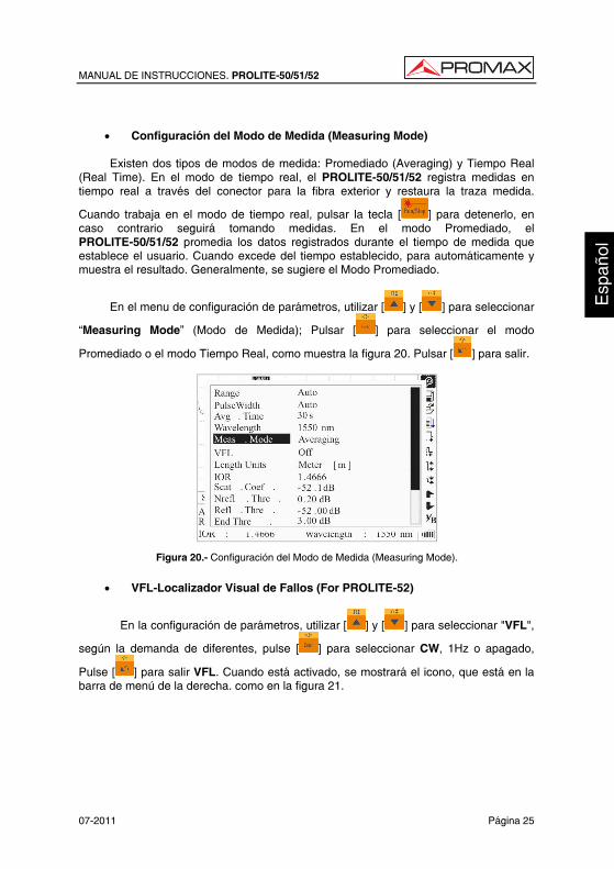
• Configuración del Modo de Medida (Measuring Mode)
Existen dos tipos de modos de medida: Promediado (Averaging) y Tiempo Real
(Real Time). En el modo de tiempo real, el PROLITE-50/51/52 registra medidas en tiempo real a través del conector para la fibra exterior y restaura la traza medida.
Cuando trabaja en el modo de tiempo real, pulsar la tecla [ ] para detenerlo, en caso contrario seguirá tomando medidas. En el modo Promediado, el PROLITE-50/51/52 promedia los datos registrados durante el tiempo de medida que establece el usuario. Cuando excede del tiempo establecido, para automáticamente y muestra el resultado. Generalmente, se sugiere el Modo Promediado.
En el menu de configuración de parámetros, utilizar [ ] y [ ] para seleccionar
“Measuring Mode” (Modo de Medida); Pulsar [ ] para seleccionar el modo
Promediado o el modo Tiempo Real, como muestra la figura 20. Pulsar [ ] para salir.
Figura 20.- Configuración del Modo de Medida (Measuring Mode).
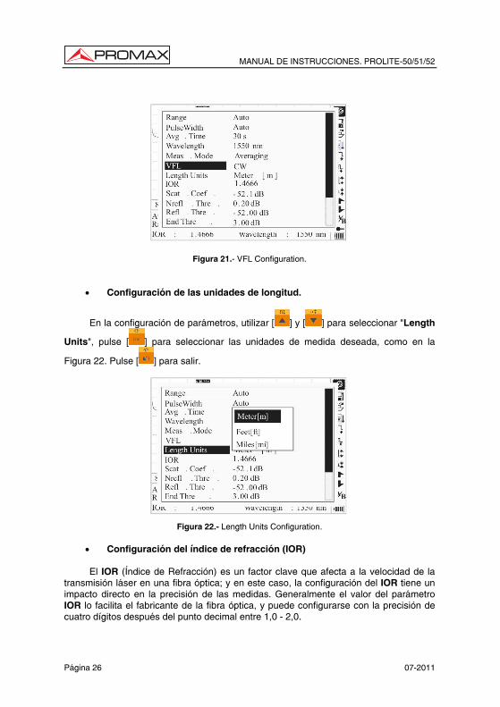
• VFL-Localizador Visual de Fallos (For PROLITE-52)
En la configuración de parámetros, utilizar [ ] y [ ] para seleccionar "VFL",
según la demanda de diferentes, pulse [ ] para seleccionar CW, 1Hz o apagado,
Pulse [ ] para salir VFL. Cuando está activado, se mostrará el icono, que está en la barra de menú de la derecha. como en la figura 21.
MANUAL DE INSTRUCCIONES. PROLITE-50/51/52
Página 26 07-2011
Figura 21.- VFL Configuration.
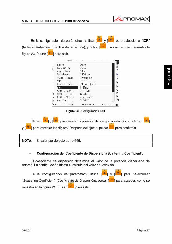
• Configuración de las unidades de longitud.
En la configuración de parámetros, utilizar [ ] y [ ] para seleccionar "Length
Units", pulse [ ] para seleccionar las unidades de medida deseada, como en la
Figura 22. Pulse [ ] para salir.
Figura 22.- Length Units Configuration.
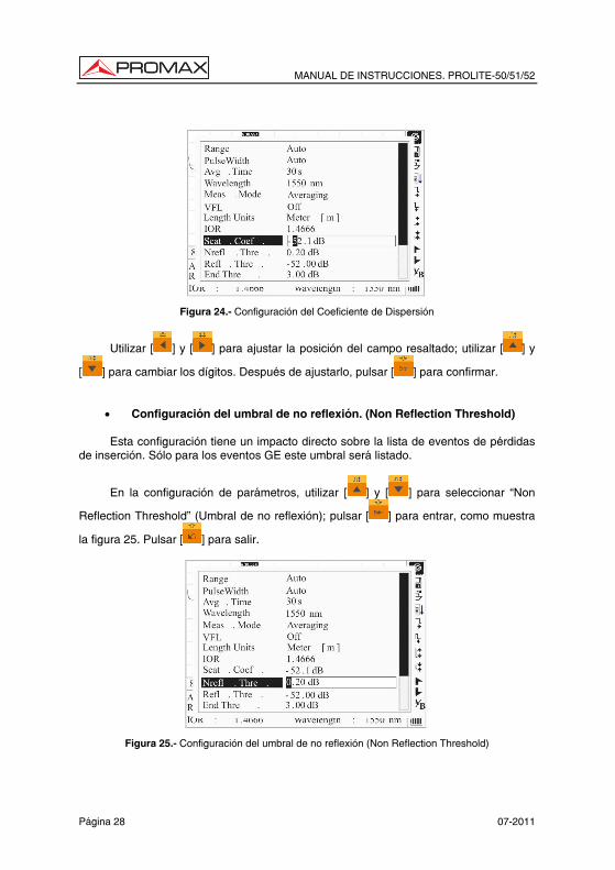
• Configuración del índice de refracción (IOR)
El IOR (Índice de Refracción) es un factor clave que afecta a la velocidad de la transmisión láser en una fibra óptica; y en este caso, la configuración del IOR tiene un impacto directo en la precisión de las medidas. Generalmente el valor del parámetro IOR lo facilita el fabricante de la fibra óptica, y puede configurarse con la precisión de cuatro dígitos después del punto decimal entre 1,0 - 2,0.
MANUAL DE INSTRUCCIONES. PROLITE-50/51/52
07-2011 Página 27
En la configuración de parámetros, utilizar [ ] y [ ] para seleccionar “IOR”
(Index of Refraction, o índice de refracción); y pulsar [ ] para entrar, como muestra la
figura 23. Pulsar [ ] para salir.
Figura 23.- Configuración IOR.
Utilizar [ ] y [ ] para ajustar la posición del campo a seleccionar; utilizar [ ]
y [ ] para cambiar los dígitos. Después del ajuste, pulsar para confirmar.
NOTA: El valor por defecto es 1.4666.
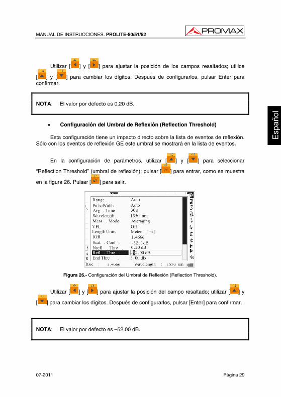
• Configuración del Coeficiente de Dispersión (Scattering Coefficient).
El coeficiente de dispersión determina el valor de la potencia dispersada de
retorno. La configuración afecta al cálculo del valor de reflexión.
En la configuración de parámetros, utilice [ ] y [ ] para seleccionar
“Scattering Coefficient” (Coeficiente de Dispersión); pulsar [ ] para acceder, como se
muestra en la figura 24. Pulsar [ ] para salir.
MANUAL DE INSTRUCCIONES. PROLITE-50/51/52
Página 28 07-2011
Figura 24.- Configuración del Coeficiente de Dispersión
Utilizar [ ] y [ ] para ajustar la posición del campo resaltado; utilizar [ ] y
[ ] para cambiar los dígitos. Después de ajustarlo, pulsar [ ] para confirmar.
• Configuración del umbral de no reflexión. (Non Reflection Threshold)
Esta configuración tiene un impacto directo sobre la lista de eventos de pérdidas de inserción. Sólo para los eventos GE este umbral será listado.
En la configuración de parámetros, utilizar [ ] y [ ] para seleccionar “Non
Reflection Threshold” (Umbral de no reflexión); pulsar [ ] para entrar, como muestra
la figura 25. Pulsar [ ] para salir.
Figura 25.- Configuración del umbral de no reflexión (Non Reflection Threshold)
MANUAL DE INSTRUCCIONES. PROLITE-50/51/52
07-2011 Página 29
Utilizar [ ] y [ ] para ajustar la posición de los campos resaltados; utilice
[ ] y [ ] para cambiar los dígitos. Después de configurarlos, pulsar Enter para confirmar.
NOTA: El valor por defecto es 0,20 dB.
• Configuración del Umbral de Reflexión (Reflection Threshold)
Esta configuración tiene un impacto directo sobre la lista de eventos de reflexión.
Sólo con los eventos de reflexión GE este umbral se mostrará en la lista de eventos.
En la configuración de parámetros, utilizar [ ] y [ ] para seleccionar
“Reflection Threshold” (umbral de reflexión); pulsar [ ] para entrar, como se muestra
en la figura 26. Pulsar [ ] para salir.
Figura 26.- Configuración del Umbral de Reflexión (Reflection Threshold).
Utilizar [ ] y [ ] para ajustar la posición del campo resaltado; utilizar [ ] y
[ ] para cambiar los dígitos. Después de configurarlos, pulsar [Enter] para confirmar.
NOTA: El valor por defecto es —52.00 dB.
MANUAL DE INSTRUCCIONES. PROLITE-50/51/52
Página 30 07-2011
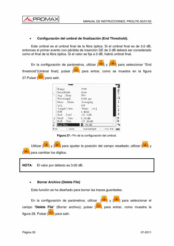
• Configuración del umbral de finalización (End Threshold).
Este umbral es el umbral final de la fibra óptica. Si el umbral final es de 3.0 dB,
entonces el primer evento con pérdida de inserción GE de 3 dB deberá ser considerado como el final de la fibra óptica. Si el valor se fija a 0 dB, habrá umbral final.
En la configuración de parámetros, utilizar [ ] y [ ] para seleccionar “End
threshold”(Umbral final); pulsar [ ] para entrar, como se muestra en la figura
27.Pulsar [ ] para salir.
Figura 27.- Fin de la configuración del umbral.
Utilizar [ ] y [ ] para ajustar la posición del campo resaltado; utilizar [ ] y
[ ] para cambiar los dígitos.
NOTA: El valor por defecto es 3.00 dB.
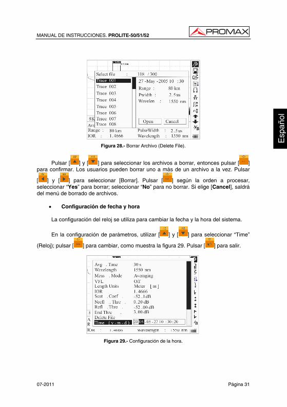
• Borrar Archivo (Delete File)
Esta función se ha diseñado para borrar las trazas guardadas.
En la configuración de parámetros, utilizar [ ] y [ ] para seleccionar el
campo “Delete File” (Borrar archivo); pulsar [ ] para entrar, como muestra la
figura 28. Pulsar [ ] para salir.
MANUAL DE INSTRUCCIONES. PROLITE-50/51/52
07-2011 Página 31
Figura 28.- Borrar Archivo (Delete File).
Pulsar [ ] y [ ] para seleccionar los archivos a borrar, entonces pulsar [ ] para confirmar. Los usuarios pueden borrar uno a más de un archivo a la vez. Pulsar
[ ] y [ ] para seleccionar [Borrar]. Pulsar [ ] según la orden a procesar, seleccionar “Yes” para borrar; seleccionar “No” para no borrar. Si elige [Cancel], saldrá del menú de borrado de archivos.
• Configuración de fecha y hora
La configuración del reloj se utiliza para cambiar la fecha y la hora del sistema.
En la configuración de parámetros, utilizar [ ] y [ ] para seleccionar “Time”
(Reloj); pulsar [ ] para cambiar, como muestra la figura 29. Pulsar [ ] para salir.
Figura 29.- Configuración de la hora.
MANUAL DE INSTRUCCIONES. PROLITE-50/51/52
Página 32 07-2011
Utilizar [ ] y [ ] para ajustar la posición del campo resaltado; utilizar [ ] y
[ ] para cambiar los dígitos. Después de configurarlo, pulsar [ ] para confirmar.
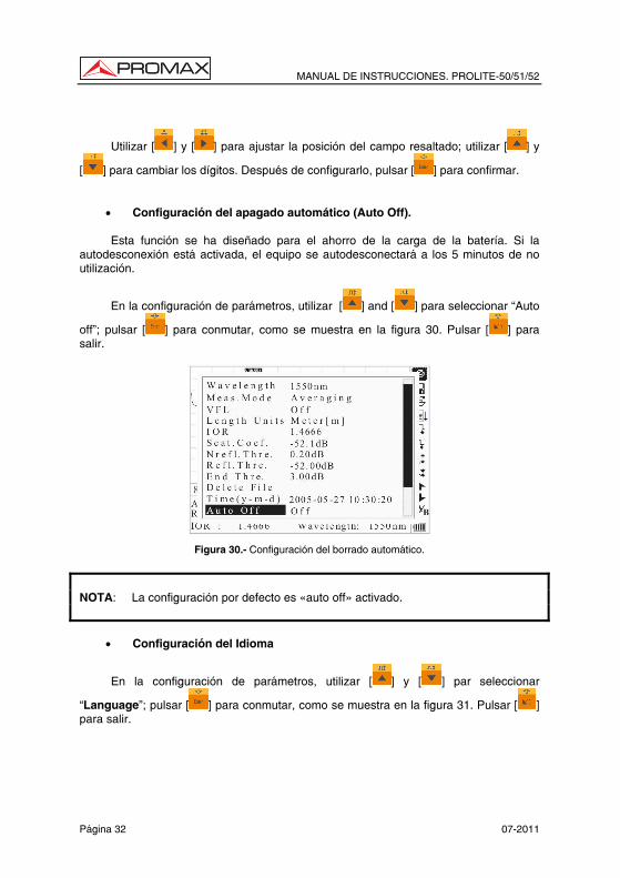
• Configuración del apagado automático (Auto Off).
Esta función se ha diseñado para el ahorro de la carga de la batería. Si la autodesconexión está activada, el equipo se autodesconectará a los 5 minutos de no utilización.
En la configuración de parámetros, utilizar [ ] and [ ] para seleccionar “Auto
off”; pulsar [ ] para conmutar, como se muestra en la figura 30. Pulsar [ ] para salir.
Figura 30.- Configuración del borrado automático.
NOTA: La configuración por defecto es «auto off» activado.
• Configuración del Idioma
En la configuración de parámetros, utilizar [ ] y [ ] par seleccionar
“Language”; pulsar [ ] para conmutar, como se muestra en la figura 31. Pulsar [ ] para salir.
MANUAL DE INSTRUCCIONES. PROLITE-50/51/52
07-2011 Página 33
Figura 31.- Configuración del Idioma.
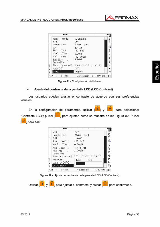
• Ajuste del contraste de la pantalla LCD (LCD Contrast)
Los usuarios pueden ajustar el contraste de acuerdo con sus preferencias
visuales.
En la configuración de parámetros, utilizar [ ] y [ ] para seleccionar
“Contraste LCD”; pulsar [ ] para ajustar, como se muestra en las Figura 32. Pulsar
[ ] para salir.
Figura 32.-. Ajuste del contraste de la pantalla LCD (LCD Contrast).
Utilizar [ ] y [ ] para ajustar el contraste, y pulsar [ ] para confirmarlo.
MANUAL DE INSTRUCCIONES. PROLITE-50/51/52
Página 34 07-2011
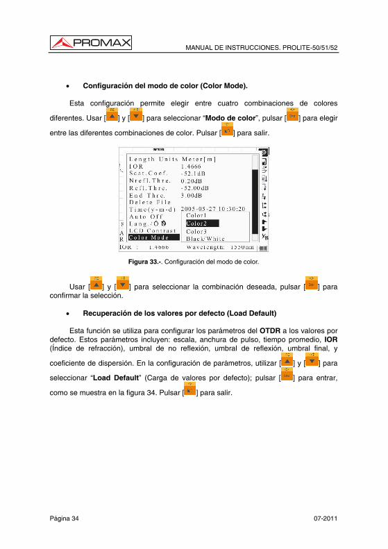
• Configuración del modo de color (Color Mode).
Esta configuración permite elegir entre cuatro combinaciones de colores
diferentes. Usar [ ] y [ ] para seleccionar “Modo de color”, pulsar [ ] para elegir
entre las diferentes combinaciones de color. Pulsar [ ] para salir.
Figura 33.-. Configuración del modo de color.
Usar [ ] y [ ] para seleccionar la combinación deseada, pulsar [ ] para confirmar la selección.
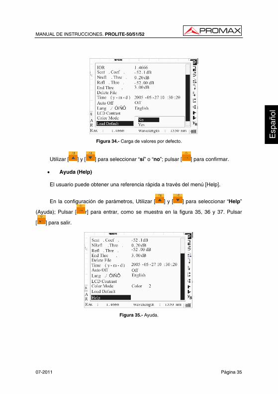
• Recuperación de los valores por defecto (Load Default)
Esta función se utiliza para configurar los parámetros del OTDR a los valores por defecto. Estos parámetros incluyen: escala, anchura de pulso, tiempo promedio, IOR (Índice de refracción), umbral de no reflexión, umbral de reflexión, umbral final, y
coeficiente de dispersión. En la configuración de parámetros, utilizar [ ] y [ ] para
seleccionar “Load Default” (Carga de valores por defecto); pulsar [ ] para entrar,
como se muestra en la figura 34. Pulsar [ ] para salir.
MANUAL DE INSTRUCCIONES. PROLITE-50/51/52
07-2011 Página 35
Figura 34.- Carga de valores por defecto.
Utilizar [ ] y [ ] para seleccionar “sí” o “no”; pulsar [ ] para confirmar.
• Ayuda (Help)
El usuario puede obtener una referencia rápida a través del menú [Help].
En la configuración de parámetros, Utilizar [ ] y [ ] para seleccionar “Help”
(Ayuda); Pulsar [ r] para entrar, como se muestra en la figura 35, 36 y 37. Pulsar
[ ] para salir.
Figura 35.- Ayuda.
MANUAL DE INSTRUCCIONES. PROLITE-50/51/52
Página 36 07-2011
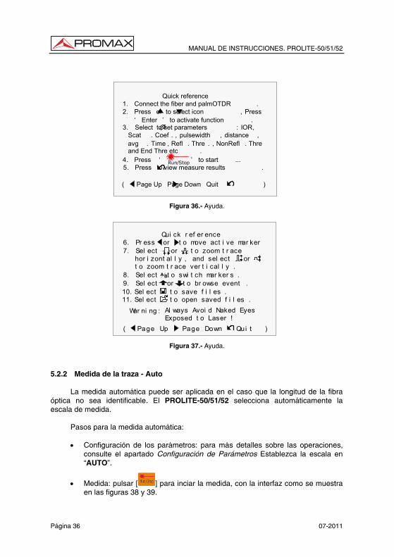
Quick reference
( Page Up Page Down Quit )
1 . Connect the fiber and palmOTDR .2 . Press or to select icon , Press
‘ Enter ’ to activate function .3 . Select to set parameters : IOR, Scat . Coef . , pulsewidth , distance , avg . Time , Refl . Thre . , NonRefl . Thre and End Thre etc . 4 . Press ‘ ’ to start ...Run / Stop 5 . Press to view measure results .
Figura 36.- Ayuda.
Qui ck r ef er ence
War ni ng : Al ways Avoi d Naked Eyes Exposed t o Laser !
( Page Up Page Down Qui t )
7. Sel ect or t o zoom t r ace
t o zoom t r ace ver t i cal l y . hor i zont al l y , and sel ect or
6. Pr ess or t o move act i ve mar ker
8. Sel ect t o swi t ch mar ker s . BA
9. Sel ect or t o br owse event .10. Sel ect t o save f i l es .11. Sel ect t o open saved f i l es .
Figura 37.- Ayuda.
5.2.2 Medida de la traza - Auto
La medida automática puede ser aplicada en el caso que la longitud de la fibra óptica no sea identificable. El PROLITE-50/51/52 selecciona automáticamente la escala de medida.
Pasos para la medida automática:
• Configuración de los parámetros: para más detalles sobre las operaciones, consulte el apartado Configuración de Parámetros Establezca la escala en “AUTO”.
• Medida: pulsar [ ] para inciar la medida, con la interfaz como se muestra en las figuras 38 y 39.
MANUAL DE INSTRUCCIONES. PROLITE-50/51/52
07-2011 Página 37
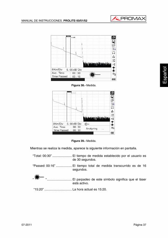
Figura 38.- Medida.
Figura 39.- Medida.
Mientras se realiza la medida, aparece la siguiente información en pantalla.
“Total: 00:30” ...................... El tiempo de medida establecido por el usuario es de 30 segundos.
“Passed: 00:16” .................. El tiempo total de medida transcurrido es de 16 segundos.
“ “ ............................ El parpadeo de este símbolo significa que el láser está activo.
“15:20” ............................... La hora actual es 15:20.
MANUAL DE INSTRUCCIONES. PROLITE-50/51/52
Página 38 07-2011
NOTA: Mientras el proceso de medida se está realizando, todas las teclas estan
inhabilitadas excepto [ ], [ ] y[ ].
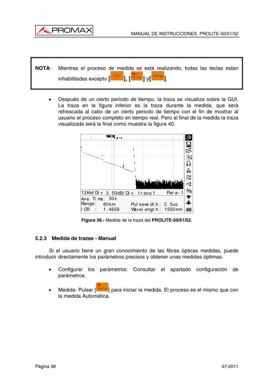
• Después de un cierto periodo de tiempo, la traza se visualiza sobre la GUI.
La traza en la figura inferior es la traza durante la medida, que será refrescada al cabo de un cierto periodo de tiempo con el fin de mostrar al usuario el proceso completo en tiempo real. Pero al final de la medida la traza visualizada será la final como muestra la figura 40.
BA
30s80km1. 4659
2. 5us1550nm
Ave. Ti me:Range:I OR :
Pul sewi dt h :Wavel engt h :
12Km/ Di v 3. 50dB/ Di v t r ace 1 Par a- 1
Figura 38.- Medida de la traza del PROLITE-50/51/52. 5.2.3 Medida de trazas - Manual
Si el usuario tiene un gran conocimiento de las fibras ópticas medidas, puede introducir directamente los parámetros precisos y obtener unas medidas óptimas.
• Configurar los parámetros: Consultar el apartado configuración de parámetros.
• Medida: Pulsar [ ] para iniciar la medida. El proceso es el mismo que con la medida Automática.
MANUAL DE INSTRUCCIONES. PROLITE-50/51/52
07-2011 Página 39
5.2.4 Medida de trazas — Motivos de errores en las medi das
Si se produce un error en la medida, puede ser debida a uno de los siguientes motivos:
• Los eventos pueden estar muy próximos el uno del otro. Acortar la anchura del pulso y probar de nuevo. Si todavía se producen fallos, por favor intente medir sobre el otro extremo de la fibra óptica.
• SNR bajo Probar utilizando una anchura de pulso mayor o incrementando el tiempo de promedio, y realizar otra prueba.
• Configuración de parámetros incorrecta. Comprobar la configuración de parámetros y realizar otra prueba.
5.3 Ventana de información.
Ítems de la ventana de información: parámetros de medida, parámetros de análisis e información relativa al marcador A/B.
Para más detalles en relación a la ventana de información, consultar el apartado 4.4.2 de la ventana de información del PROLITE-50/51/52. 5.3.1 Conmutar entre los ítem de la ventana de información.
En la GUI de la figura 5, pulsar [ ] y los ítems de la ventana de información se visualizarán por este orden: parámetros de medida → información de análisis → Lista de eventos → información del marcador A/B → parámetros de medida. 5.3.2 Repaso de la Lista de Eventos
En la GUI de la figura 5, pulsar [ ], los ítems de la ventana de información conmutarán a la información de la lista de eventos
Utilizar [ ] y [ ] para seleccionar ó , entonces pulsar [Enter] para revisar la lista de eventos: es para desplazarse al evento anterior o para desplazarse al evento posterior.Esta operación también se puede realizar mediante la
combinación de las teclas: [ ] + [ ] o [ ] + [Enter] del teclado.
MANUAL DE INSTRUCCIONES. PROLITE-50/51/52
Página 40 07-2011
5.3.3 Cursores
El PROLITE-50/51/52 dispone de dos cursores (A y B) que pueden ser desplazados a lo largo de la traza proporcionando información específica en ese punto.
Para conmutar el cursor activo utilizar [ ] y [ ] para seleccionar el icono BA,
después pulsar [Enter] para conmutar entre el marcador A/B.
Utilizar [ ] y [ ] para desplazar el marcador A ó B.
Pulsar [ ] para cambiar la ventana de información al marcador A/B.
Pulsar [ ] ó [ ] para cambiar la posición del marcador A ó B, y la información del marcador A/B cambiará de acuerdo con la ventana de información. 5.4 Aumento y disminución de la visualización de la traza
Para poder visualizar los eventos con mayor precisión, el equipo incorpora las funciones de aumento y disminución de visualización de la traza.
• La función indicada con el icono [ ] en el menú, sirve para aumentar la
traza horizontalmente, mientras que el icono [ ] sirve para disminuirla.
• La función indicada con el icono [ ] en el menú sirve para aumentar la
traza verticalmente mientras que el icono [ ] sirve para disminuirla.
Utilizar [ ] y [ ] para seleccionar la función deseada y pulsar (ENTER)
La visualización de la traza puede ser aumentada hasta 10 veces. En el caso del aumento horizontal, se centrará en pantalla la zona de traza del cursor que esté activa.
Usar [ ] y [ ] para mover los cursores por la traza con mayor precisión.
La función de conmutación del cursor (A/B) y de desplazamiento entre eventos [ ] y [ ] no modifica la visualización de la traza y centra automáticamente en la pantalla el cursor o evento seleccionado con estas funciones. Las funciones de aumento / disminución, también pueden ser ejecutadas mediante una combinación de teclas de modo de acceso rápido.
MANUAL DE INSTRUCCIONES. PROLITE-50/51/52
07-2011 Página 41
• Para aumentar la traza horizontalmente mantener pulsado [ ] y
seguidamente [ ]
• Para disminuir la traza horizontalmente mantener pulsado [ ] y
seguidamente [ ]
• Para aumentar la traza verticalmente mantener pulsado [ ] y
seguidamente [ ]
• Para disminuir la traza verticalmente mantener pulsado [ ] y
seguidamente [ ]
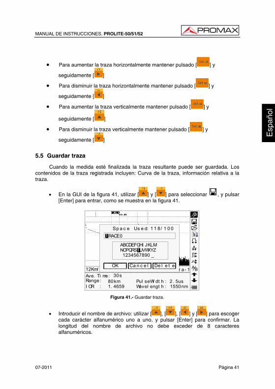
5.5 Guardar traza
Cuando la medida esté finalizada la traza resultante puede ser guardada. Los contenidos de la traza registrada incluyen: Curva de la traza, información relativa a la traza.
• En la GUI de la figura 41, utilizar [ ] y [ ] para seleccionar , y pulsar [Enter] para entrar, como se muestra en la figura 41.
30s80km1. 4659
2. 5us1550nm
Ave. Ti me:Range:I OR :
Pul seWi dt h :Wavel engt h :
12Km/ Di v 3.50dB/Div t race1.t rc Par a- 1Ca n c e l
ABCDEFGHI JKLMNOPQRSTUVWXYZ 1234567890 _
Sp a c e Us e d: 1 1 8/ 1 0 0
OK De l e t e
RACE0T
T
BA
Figura 41.- Guardar traza.
• Introducir el nombre de archivo: utilizar [ ], [ ], [ ] y [ ] para escoger cada carácter alfanumérico uno a uno, y pulsar [Enter] para confirmar. La longitud del nombre de archivo no debe exceder de 8 caracteres alfanuméricos.
MANUAL DE INSTRUCCIONES. PROLITE-50/51/52
Página 42 07-2011
• Guardar el archivo: utilizar [ ], [ ], [ ] y [ ] para seleccionar “OK”, pulsar [Enter] para guardar.
• Cancelar la operación de guardar: utilizar [ ], [ ], [ ] y [ ] para seleccionar “cancel”, pulsar [Enter] para cancelar la operación de “guardar archivo”.
• Borrar los caracteres alfanuméricos: utilizar [ ], [ ], [ ] y [ ] para seleccionar “Delete”, pulsar [Enter] para borrar los caracteres alfanuméricos.
• Espacio de memoria: 118/300 significa un espacio total de memoria de 300 archivos; ya ha guardado 118 archivos en memoria.
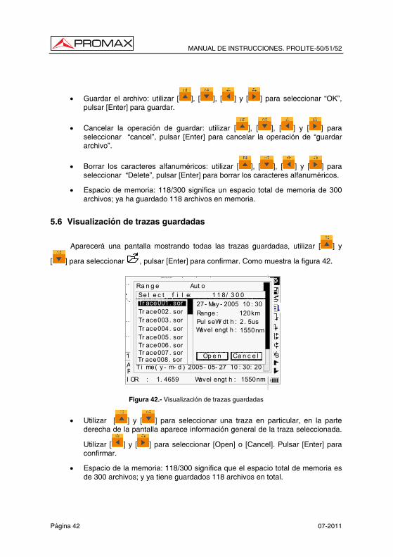
5.6 Visualización de trazas guardadas
Aparecerá una pantalla mostrando todas las trazas guardadas, utilizar [ ] y
[ ] para seleccionar , pulsar [Enter] para confirmar. Como muestra la figura 42.
30s80km1. 4659
2.5us1550nm
Ave. Ti me:Range :I OR :
PulseW idth:Wavel engt h :
12Km/ Di v 3.50dB/ Div t race1.t rc 15:20 BA30s
80km 2500ns
Ra n g e
Wa v e l e n g t h 1550nm
Pu l s e Wi d t h Aut oAv e. T i me 30s
I OR 1. 4659
Nr e f l . T h r e. 0. 20dBRe f l . Th r e. - 52. 00dBEn d Th r e. 3. 00dB
Sc a t . Co e f . - 51. 50dB
Av e r a g i n gMe a s . Mo d e
De l e t e F i l eT i me( y - m- d ) 2005- 05- 27 10 : 30: 20
Aut oSe l e c t f i l e: 1 1 8/ 3 0 0Tr ace001. sorTr ace002. sorTr ace003. sorTr ace004. sorTr ace005. sor
Ca n c e lOp e nTr ace006. sorTr ace007. sorTr ace008. sor
27- May - 2005 10 : 30Range : 120kmPul seWi dt h : 2. 5usWavel engt h : 1550nm
Figura 42.- Visualización de trazas guardadas
• Utilizar [ ] y [ ] para seleccionar una traza en particular, en la parte derecha de la pantalla aparece información general de la traza seleccionada.
Utilizar [ ] y [ ] para seleccionar [Open] o [Cancel]. Pulsar [Enter] para confirmar.
• Espacio de la memoria: 118/300 significa que el espacio total de memoria es de 300 archivos; y ya tiene guardados 118 archivos en total.
MANUAL DE INSTRUCCIONES. PROLITE-50/51/52
07-2011 Página 43
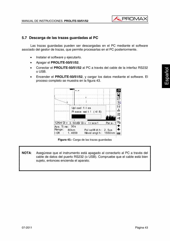
5.7 Descarga de las trazas guardadas al PC
Las trazas guardadas pueden ser descargadas en el PC mediante el software asociado del gestor de trazas, que permite procesarlas en el PC posteriormente.
• Instalar el software y ejecutarlo.
• Apagar el PROLITE-50/51/52.
• Conectar el PROLITE-50/51/52 al PC a través del cable de la interfaz RS232 o USB.
• Encender el PROLITE-50/51/52, y cargar los datos mediante el software. El proceso completo se muestra en la figura 43.
30s80km1. 4659
2. 5us1550nm
Ave. Ti me:Range:I OR :
Pul seWi dt h :Wavel engt h :
12Km/ Di v 3. 50dB/ Di v t r ace1 Par a- 1
Upl oad f i l esPl ease wai t ! ( 4/ 8)
BA
Figura 43.- Carga de las trazas guardadas
NOTA: Asegúrese que el instrumento está apagado al conectarlo al PC a través del
cable de datos del puerto RS232 (o USB). Compruebe que el cable está bien sujeto, entonces encienda el aparato.
MANUAL DE INSTRUCCIONES. PROLITE-50/51/52
Página 44 07-2011
6. MANTENIMIENTO 6.1 Mantenimiento de las baterías
La batería de este equipo es una batería NiMH recargable. Las baterías NiMH han sido cuidadosamente instaladas y verificadas. Por favor no abra el aparato para manipular las baterías sin motivo justificado. • Precauciones durante la operación del equipo:
El siguiente procedimiento puede conducir a la desconexión automática del equipo:
El equipo pasa a autodesconexión cuando detecta una alimentación insuficiente durante su funcionamiento y aparece el indicador de alimentación baja en la pantalla LCD.
Si no es utilizado durante un largo periodo de tiempo y presenta una carga insuficiente, el equipo se desconectará automáticamente unos segundos después de su puesta en marcha con el objeto de proteger a las baterías de una descarga excesiva. Las baterías internas deben ser recargadas inmediatamente mediante el adaptador de corriente.
NOTA: Notas para el mantenimiento de las baterías del instrumento: A fin que el PROLITE-50/51/52 cumpla las especificaciones (incluyendo las
baterías) la temperatura de almacenamiento debe estar entre 0 °C y 40 °C. Los equipos deben almacenarse en condiciones de baja humedad.
El equipo incorpora una batería recargable NiMH interna. No sustituya la
batería por sí mismo. Si se prevee no utilizar el equipo durante un largo periodo de tiempo (durante
más de dos meses), se aconseja recargarla cada mes.
MANUAL DE INSTRUCCIONES. PROLITE-50/51/52
07-2011 Página 45
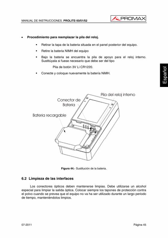
• Procedimiento para reemplazar la pila del reloj.
Retirar la tapa de la bateria situada en el panel posterior del equipo.
Retire la bateria NIMH del equipo
Bajo la bateria se encuentra la pila de apoyo para el reloj interno. Sustitúyala si fuese necesario que debe ser del tipo
Pila de botón 3V Li CR1220.
Conecte y coloque nuevamente la batería NiMH.
RTC ClockBattery
ChargeableBattery
Jack forChargeable
BatteryConector de
Bateria
Pila del reloj interno
Bateria recargable
Figura 44.- Sustitución de la bateria.
6.2 Limpieza de las interfaces
Los conectores ópticos deben mantenerse limpias. Debe utilizarse un alcohol especial para limpiar la salida óptica. Colocar siempre los tapones de protección contra el polvo cuando se prevea que el equipo no va ha ser utilizado durante un largo periodo de tiempo, manteniéndolos limpios.
MANUAL DE INSTRUCCIONES. PROLITE-50/51/52
Página 46 07-2011
Adicionalmente, los extremos deben limpiarse periódicamente.
• Efectos de la limpieza de las interfaces y conectores
El diámetro del núcleo de la fibra óptica es de 9 um, y el diámetro de las partículas de polvo oscila entre 1/100 a 1/1/10 um. Es decir, comparativamente el tamaño de las partículas de polvo pueden cubrir parte del extremo óptico y en consecuencia degradar el rendimiento del instrumento.
Además, la densidad de potencia puede quemar las partículas de polvo en la fibra óptica y provocar mayores daños (por ejemplo, 0 dBm de potencia óptica pueden producir unos 16000000 W/m*m de densidad de potencia en una fibra monomodo). En este caso, la medidas serán imprecisas e irreversibles.
• Instrucciones de seguridad para seguir antes de proceder a limpiar
a) Asegúrese que el instrumento está desconectado de la alimentación y apagado cuando proceda a su limpieza.
b) Cualquier operación contraria a las instrucciones descritas puede resultar peligrosa y provocar lesiones por exposición al láser.
c) Asegúrese que la fuente de luz láser está desconectada siempre que limpie cualquier conector óptico.
d) Cuando el equipo se encuentra en funcionamiento, por favor evite mirar directamente a la salida óptica. Aunque la radiación láser sea invisible puede provocar graves lesiones a la vista.
e) Tome precauciones frente al choque eléctrico y asegúrese que la alimentación AC se encuentra desconectada del aparato antes de su limpieza. Siempre utilice un paño seco o ligeramente humedecido para limpiar el chasis del instrumento y nunca limpie en el interior.
f) Por favor no añada ningún accesorio al instrumento óptico o calibre por si mismo el equipo.
g) Para su mantenimiento, diríjase siempre a profesionales cualificados.
MANUAL DE INSTRUCCIONES. PROLITE-50/51/52
07-2011 Página 47
• Herramientas para la limpieza de interfaces y conectores
a) Limpiador para fibra óptica (para limpieza de conectores ópticos).
b) Bastoncillo limpiador para fibra óptica (para limpieza de las salidas ópticas).
c) Tisú para la limpieza de fibras ópticas (para la limpieza de interfaces ópticos)
d) Alcohol isopropílico.
e) Bola de algodón.
f) Papel tisú.
g) Cepillo de limpieza.
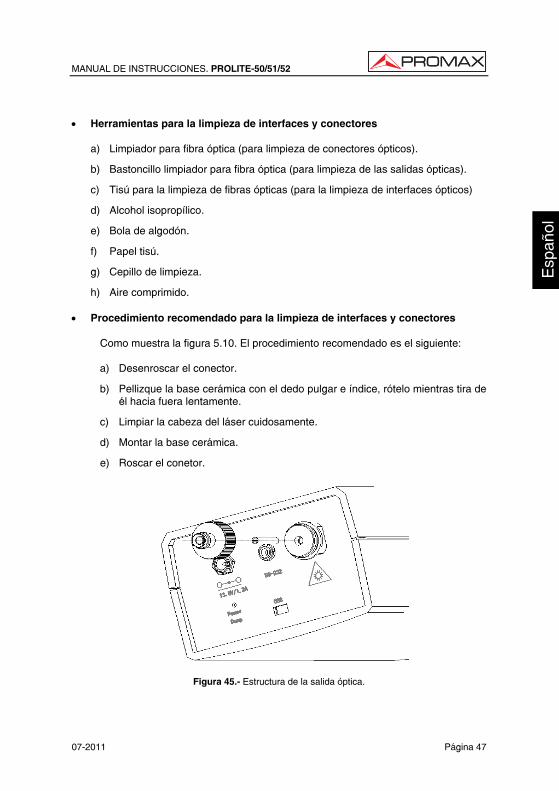
h) Aire comprimido. • Procedimiento recomendado para la limpieza de interfaces y conectores
Como muestra la figura 5.10. El procedimiento recomendado es el siguiente:
a) Desenroscar el conector.
b) Pellizque la base cerámica con el dedo pulgar e índice, rótelo mientras tira de él hacia fuera lentamente.
c) Limpiar la cabeza del láser cuidosamente.
d) Montar la base cerámica.
e) Roscar el conetor.
Figura 45.- Estructura de la salida óptica.
MANUAL DE INSTRUCCIONES. PROLITE-50/51/52
Página 48 07-2011
6.3 Requerimientos de calibración
Se recomienda calibrar el instrumento cada dos años. Por favor, contacte con los distribuidores más próximos para una calibración correcta. 6.4 Recomendaciones de limpieza
PRECAUCIÓN
Para limpiar la caja, asegurarse de que el dispositivo está desconectado.
PRECAUCIÓN
No se use para la limpieza del panel frontal y en particular de los visores, alcohol o sus derivados, estos productos pueden atacar las propiedades mecánicas de los materiales y disminuir su tiempo de vida útil. La caja se limpiará con una ligera solución de detergente con agua y aplicada mediante un paño suave humedecido. Secar completamente antes de volver a usar el equipo.
USER’S MANUAL. PROLITE-50/51/52
Eng
lish
T A B L E O F C O N T E N T S 1. GENERAL.................................................................................................................. 1
1.1 Specifications ...................................................................................................... 3 2. SAFETY RULES........................................................................................................ 5
2.1 General................................................................................................................ 5 2.2 Specific precautions ............................................................................................ 5 2.3 Descriptive Examples of Over-Voltage Categories ............................................. 6
3. DESCRIPTION OF CONTROLS ELEMENTS........................................................... 7 3.1 Patch panel ......................................................................................................... 7 3.2 Keypad Functions................................................................................................ 8
4. BASIC INFORMATION OF PROLITE-50/51/52 ...................................................... 11 4.1 Principle of Prolite-50/51/52 .............................................................................. 11 4.2 Basic definition and classification of events ...................................................... 11
4.2.1 Events ......................................................................................................... 11 4.2.1.1 Reflection Events.................................................................................. 12 4.2.1.2 Non-reflection Events ........................................................................... 12 4.2.1.3 Inspection Event ................................................................................... 13
4.3 Measurement Application of PROLITE-50/51/52 .............................................. 13 4.3.1 Measurement Contents of PROLITE-50/51/52 ........................................... 13 4.3.2 Trace Analysis of PROLITE-50/51/52......................................................... 13
4.4 Trace Display Screen of PROLITE-50/51/52 .................................................... 14 4.4.1 Trace Display of PROLITE-50/51/52 .......................................................... 14 4.4.2 Information Window of PROLITE-50/51/52................................................. 15
4.4.2.1 Measurement Trace Parameters.......................................................... 15 4.4.2.2 Event List .............................................................................................. 16 4.4.2.3 Accuracy............................................................................................... 17
5. TRACE MEASUREMENT PROCESS..................................................................... 19 5.1 Instructions on Graphic User Interface (GUI) .................................................... 19
5.1.1 Menu Bar of PROLITE-50/51/52................................................................. 20 5.1.2 Battery Recharge Status............................................................................. 20
5.2 Trace Measurement of PROLITE-50/51/52....................................................... 21 5.2.1 Parameter Configuration on PROLITE-50/51/52 on Menu Bar. ................. 22 5.2.2 Trace Measurement - Auto ......................................................................... 38 5.2.3 Trace Measurement - Manual..................................................................... 40 5.2.4 Trace Measurement — Reasons of Measurement Failures......................... 40
5.3 Information Window........................................................................................... 41 5.3.1 Switch between Information Window Items ................................................ 41 5.3.2 Review Event List ....................................................................................... 41 5.3.3 Cursors ....................................................................................................... 41
5.4 Increasing and decreasing of the trace visualization......................................... 42 5.5 Save Trace ........................................................................................................ 42 5.6 Browse Saved Traces ....................................................................................... 43 5.7 Upload Saved Traces........................................................................................ 45

USER’S MANUAL. PROLITE-50/51/52 6. MAINTENANCE....................................................................................................... 47
6.1 Maintenance of Batteries................................................................................... 47 6.2 Cleaning of Interfaces ....................................................................................... 49 6.3 Calibration Requeriments.................................................................................. 51 6.4 Cleaning Recommendations ............................................................................. 51
USER’S MANUAL. PROLITE-50/51/52
07-2011 Page 1
Eng
lish
OPTICAL REFLECTOMETER (OTDR) PROLITE-50/51/52
1. GENERAL
PROLITE-50/51/52 are the preferred choice for the measurement of optical fiber’s specifications. With PROLITE-50/51/52, you can make assessment of one single optical fiber or a whole optical fibre chain. Especially, you can directly observe loss and events distribution of optical fibre chain.
PROLITE-50/51/52 check the transmission quality of optic fibre through measurement of backward scattered lights. Standard organizations like International Telecom Union (ITU) define backward scattered lights as effective analysis means of measurement of optical fibre loss. Backward scattering is also the only effective way of connector inspection, which can be applied to measure the length of optical fibre, too. Therefore, PROLITE-50/51/52 is a useful tool for optical fibre manufacturing, installation and maintenance.
Therefore, the PROLITE-50/51/52 is a very useful tool for the optical fibre manufacturing, installation and maintenance.
PROLITE-50/51/52 works through reviewing “events” in optical fibre (for example, irregularities and connectors), which is quite helpful for quality control for those who are in charge of optical fibre manufacturing, installation and maintenance. PROLITE-50/51/52 can help identify the irregularities in optical fibre, locate them, and measure their attenuation, relevant loss and their homogeneity.
PROLITE-50/51/52 is more helpful for field operation. It can help to check the qualification of optical fibre chain circuit on a regular basis. For the purpose of future maintenance, transmission quality and condition of optical fibre need to be recorded and stored, which includes measurement of optical path, total loss, and loss of all tie-ins and connectors.
Besides, PROLITE-50/51/52 are easy to use, small and compact. According to the ergonomics, they are designed to fully embody the user's convenience with its large LCD display and graphical interface. They can save and transfer the measurement curves data to a PC by the provided software for further analysing, reporting and printing.
USER’S MANUAL. PROLITE-50/51/52
Page 2 07-2011
PROLITE-50/51/52 feature by:
• Basic applications:
a) Measure the length of optical fibre and cable.
b) Measure the distance between two points on optical fibre and cable.
c) Locate faults and ruptures of optical fibre and cable.
d) Display distribution curve of optical fibre and cable loss.
e) Measure attenuation coefficient of optical fibre and cable.
f) Measure loss between two points on optical fibre and cable.
g) Measure loss of tie-ins.
h) Measure reflection of reflection events of optical fibre and cable.
For a specific event (transmission quality changed due to faults caused by
welding, connector, bending etc.), the following measurements can be carried out with PROLITE-50/51/52:
a) For each event: distance, loss and reflection;
b) For each section of optical fibre: length and loss of dB or dB/Km;
c) For the whole optical fibre chain: length and loss of dB;
• Large Colorful LCD display with auto or manual adjustment of contrast.
• Backlight LCD display supports night operation.
• Easy operation with trace graphic display.
• Trace storage function.
• RS232/USB Data upload port.
• PC analysis software-Trace Manager for analysing and reporting previously stored data.
• Auto off function conserving battery life.
• DC/AC power supply.
• Auto recharging, over 8 hours operation for one charge.
USER’S MANUAL. PROLITE-50/51/52
07-2011 Page 3
Eng
lish
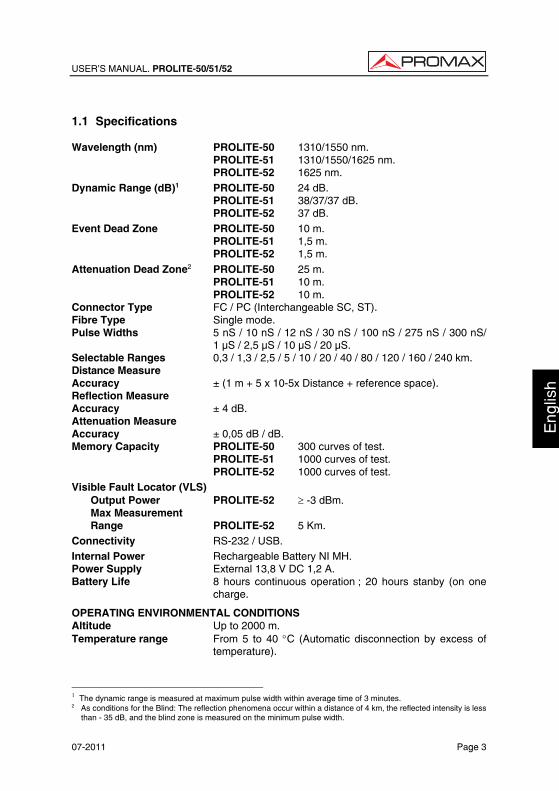
1.1 Specifications Wavelength (nm) PROLITE-50 1310/1550 nm. PROLITE-51 1310/1550/1625 nm. PROLITE-52 1625 nm. Dynamic Range (dB)1 PROLITE-50 24 dB. PROLITE-51 38/37/37 dB. PROLITE-52 37 dB. Event Dead Zone PROLITE-50 10 m. PROLITE-51 1,5 m. PROLITE-52 1,5 m. Attenuation Dead Zone2 PROLITE-50 25 m. PROLITE-51 10 m. PROLITE-52 10 m. Connector Type FC / PC (Interchangeable SC, ST). Fibre Type Single mode. Pulse Widths 5 nS / 10 nS / 12 nS / 30 nS / 100 nS / 275 nS / 300 nS/
1 µS / 2,5 µS / 10 µS / 20 µS. Selectable Ranges 0,3 / 1,3 / 2,5 / 5 / 10 / 20 / 40 / 80 / 120 / 160 / 240 km. Distance Measure Accuracy ± (1 m + 5 x 10⁻⁵x Distance + reference space). Reflection Measure Accuracy ± 4 dB. Attenuation Measure Accuracy ± 0,05 dB / dB. Memory Capacity PROLITE-50 300 curves of test. PROLITE-51 1000 curves of test. PROLITE-52 1000 curves of test. Visible Fault Locator (VLS) Output Power PROLITE-52 ≥ -3 dBm. Max Measurement Range PROLITE-52 5 Km. Connectivity RS-232 / USB. Internal Power Rechargeable Battery NI MH. Power Supply External 13,8 V DC 1,2 A. Battery Life 8 hours continuous operation ; 20 hours stanby (on one
charge.
OPERATING ENVIRONMENTAL CONDITIONS Altitude Up to 2000 m. Temperature range From 5 to 40 °C (Automatic disconnection by excess of
temperature).
1 The dynamic range is measured at maximum pulse width within average time of 3 minutes. 2 As conditions for the Blind: The reflection phenomena occur within a distance of 4 km, the reflected intensity is less
than - 35 dB, and the blind zone is measured on the minimum pulse width.
USER’S MANUAL. PROLITE-50/51/52
Page 4 07-2011
Max. relative humidity 80 % (up to 31°C), decreasing lineally up to 50% at
40 °C. MECHANICAL FEATURES Dimensions 220 (H) x 110 (W) x 70 (T) mm. Weight 1 kgs. ACCESORIES AL005 Power Supply AC 100V/240V 50/60 Hz.
Carrying Bag.
0 MI1858 User’s Manual.
Communication software CD.
Communication with PC Cable.
AD500 Adapter ST (Optional).
AD502 Adapter SC (optional).
RECOMMENDATIONS ABOUT THE PACKING
It is recommended to keep all the packing material in order to return the equipment, if necessary, to the Technical Service.
USER’S MANUAL. PROLITE-50/51/52
07-2011 Page 5
Eng
lish
2. SAFETY RULES 2.1 General * The safety could not be assured if the instructions for use are not closely
followed. * This is a class I equipment, for safety reasons plug it to a supply line with the
corresponding ground terminal. * When using some of the following accessories use only the specified ones to
ensure safety. Mains power supply AL-005.
Watch Battery. * Observe all specified rating both of supply and measurement. * Remember that voltages higher than 70 V DC or 33 V AC rms are dangerous. * Use this instrument under the specified environmental conditions. * The user is only authorised to carry out the following maintenance operations:
Any other change on the equipment should be carried out by qualified personnel.
* Follow the cleaning instructions described in the Maintenance paragraph. 2.2 Specific precautions
CAUTION It is recommended do not watch directly the laser beam.
The use of devices that are not the specified ones in this manual as well as internal manipulation of the equipment can be cause of dangerous radiation.
USER’S MANUAL. PROLITE-50/51/52
Page 6 07-2011
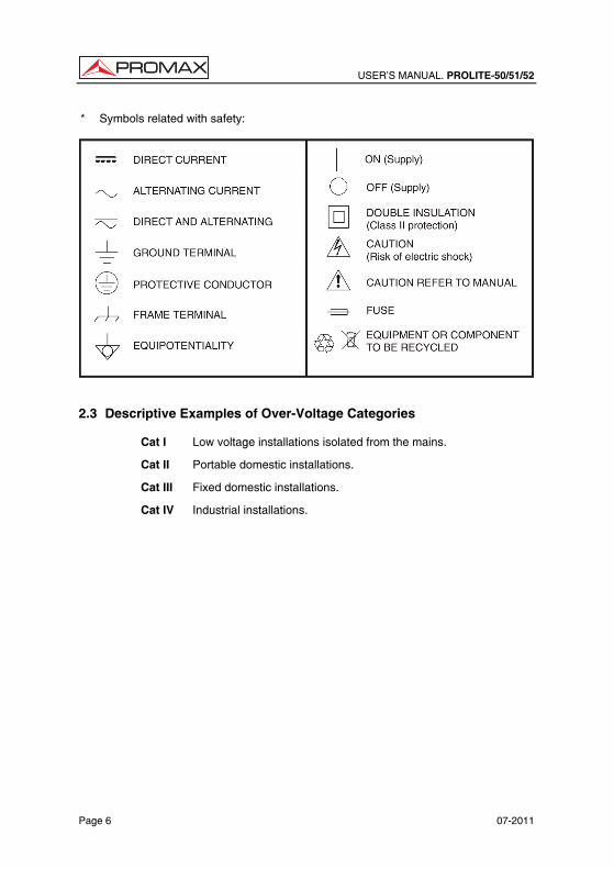
* Symbols related with safety:
2.3 Descriptive Examples of Over-Voltage Categories Cat I Low voltage installations isolated from the mains.
Cat II Portable domestic installations.
Cat III Fixed domestic installations.
Cat IV Industrial installations.
USER’S MANUAL. PROLITE-50/51/52
07-2011 Page 7
Eng
lish
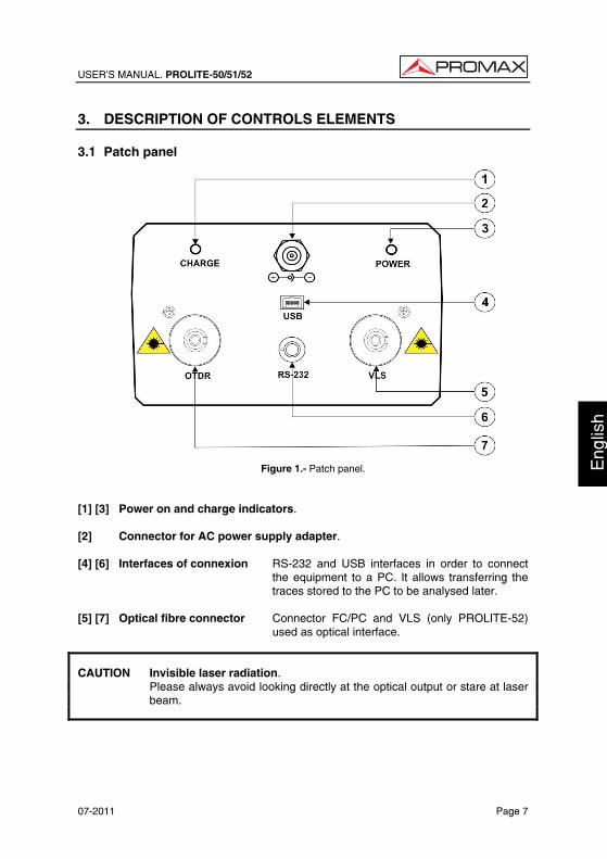
3. DESCRIPTION OF CONTROLS ELEMENTS 3.1 Patch panel
Figure 1.- Patch panel. [1] [3] Power on and charge indicators. [2] Connector for AC power supply adapter. [4] [6] Interfaces of connexion RS-232 and USB interfaces in order to connect
the equipment to a PC. It allows transferring the traces stored to the PC to be analysed later.
[5] [7] Optical fibre connector Connector FC/PC and VLS (only PROLITE-52)
used as optical interface.
CAUTION Invisible laser radiation. Please always avoid looking directly at the optical output or stare at laser
beam.
USER’S MANUAL. PROLITE-50/51/52
Page 8 07-2011
3.2 Keypad Functions
[1][2][3][4]
[5][6]
[7]
[8]
[9]
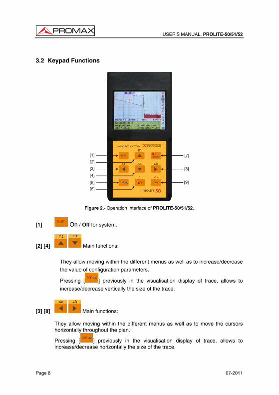
Figure 2.- Operation Interface of PROLITE-50/51/52.
[1] On / Off for system.
[2] [4] Main functions:
They allow moving within the different menus as well as to increase/decrease
the value of configuration parameters.
Pressing [ ] previously in the visualisation display of trace, allows to
increase/decrease vertically the size of the trace.
[3] [8] Main functions:
They allow moving within the different menus as well as to move the cursors horizontally throughout the plan.
Pressing [ ] previously in the visualisation display of trace, allows to increase/decrease horizontally the size of the trace.
USER’S MANUAL. PROLITE-50/51/52
07-2011 Page 9
Eng
lish
[5] Pressing it previously allows executing the secondary functions. Also it serves to cancel the zoom in / zoom out actions for trace visualisation, which has been done.
[6] Main functions:
This key allows going forward through pages from Help, cancelling the selected operation, exiting from configuration menu and changing between information windows from visualised trace.
Press [ ] to review the previous trace events.
[7] Key to start/stop the measurement process.
[9] Press this key to confirm the operation selected.
Press [ ] to review the later trace events.

USER’S MANUAL. PROLITE-50/51/52
Page 10 07-2011
USER’S MANUAL. PROLITE-50/51/52
07-2011 Page 11
Eng
lish
4. BASIC INFORMATION OF PROLITE-50/51/52 4.1 Principle of Prolite-50/51/52
OTDR is a measurement instrument for identifying optic fiber transmission features. The instrument is mainly used to measure attenuation of a whole optic fiber chain and provide attenuation details relating to length, namely detect, locate and measure any event in optic fiber chain (events refer to faults caused by welding, connectors, and bending whose transmission change can be measured). Its non-destructive, one-end connection, and rapid measurement has made the PROLITE-50/51/52 an indispensable tool for manufacture, construction, and maintenance of optic fiber.
The faults and heterogeneity of optic fiber it self cause Rayleigh scattering of light pulse transmitted in optic fiber. Part of light pulse is scattered in the reverse direction, and this is called Rayleigh backward scattering, which actually provides attenuation details relating to length.
Information relating to distance is obtained through time information (that’s the reason why there is “time Domain” in the name of OTDR). Fresnel reflection occurs at the boundary between two media of different IOR (for example, connections of faults, connectors, or optic fiber end). This reflection is used to locate the discontinuous points on optic fiber. The magnitude of reflection depends on the difference between IOR and the smoothness of boundary.
PROLITE-50/51/52 sends out a light pulse into connected optic fiber, and receive reflections of events and backward scattering power of pulse in time. Locus will be displayed on LCD. The y-axis is dB value of backward scattering power, and the x-axis is the distance. 4.2 Basic definition and classification of events 4.2.1 Events
Events refer to any abnormal points causing attenuation or sudden change of scattering power besides the normal scattering of optic fiber, which include all kinds of losses like bending, connections and ruptures. Events points displayed on LCD are abnormal points that cause traces to deviate from straight line.
Events can be classified as reflection events and non-reflection events.
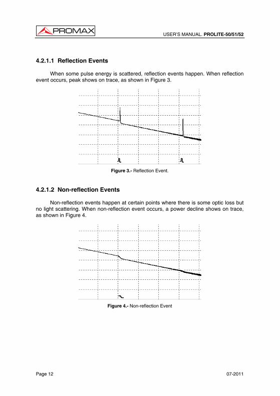
USER’S MANUAL. PROLITE-50/51/52
Page 12 07-2011
4.2.1.1 Reflection Events
When some pulse energy is scattered, reflection events happen. When reflection event occurs, peak shows on trace, as shown in Figure 3.
Figure 3.- Reflection Event. 4.2.1.2 Non-reflection Events
Non-reflection events happen at certain points where there is some optic loss but no light scattering. When non-reflection event occurs, a power decline shows on trace, as shown in Figure 4.
Figure 4.- Non-reflection Event
USER’S MANUAL. PROLITE-50/51/52
07-2011 Page 13
Eng
lish
4.2.1.3 Inspection Event
PROLITE-50/51/52 sends off a light pulse into the optic fiber to be inspected, and then receive returning light signals, and starts calculating the “event” distance. The farther the distance is, the longer time need for scattered light to be received by the instrument. Event distance can be calculated according to the time of receiving events signals.
Through inspection of scattered signals, properties of optic fiber, connectors, tie-ins can be identified. 4.3 Measurement Application of PROLITE-50/51/52
PROLITE-50/51/52 displays power relating to distance of returning signals. This information can be used to identify the main properties of an optic fiber chain. 4.3.1 Measurement Contents of PROLITE-50/51/52
• Event location (distance),end or rupture of optic fiber chain.
• Attenuation coefficient of fiber.
• Loss of a single event (for example, one optic tie-in), or total loss from upper end to end.
• Range of a single event like reflection of connectors (or grade of reflection).
• Auto measurement of cumulative loss of a single event. 4.3.2 Trace Analysis of PROLITE-50/51/52
The trace analysis of PROLITE-50/51/52 is fully automatic. The trace locates:
• Reflection events of connections and mechanic tie-ins.
• Non-reflection events (usually at welding tie-ins).
• End of optic fiber (Through scanning the first loss event that is larger than end threshold, end of optic fiber can be identified).
• Events list: event type, loss, reflection and distance.
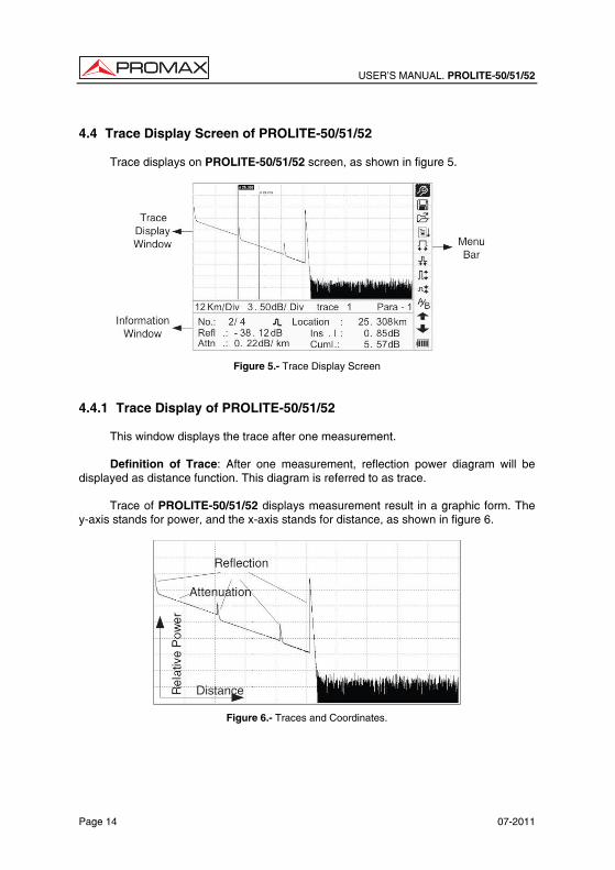
USER’S MANUAL. PROLITE-50/51/52
Page 14 07-2011
4.4 Trace Display Screen of PROLITE-50/51/52
Trace displays on PROLITE-50/51/52 screen, as shown in figure 5.
Figure 5.- Trace Display Screen 4.4.1 Trace Display of PROLITE-50/51/52
This window displays the trace after one measurement.
Definition of Trace: After one measurement, reflection power diagram will be displayed as distance function. This diagram is referred to as trace.
Trace of PROLITE-50/51/52 displays measurement result in a graphic form. The y-axis stands for power, and the x-axis stands for distance, as shown in figure 6.
Figure 6.- Traces and Coordinates.
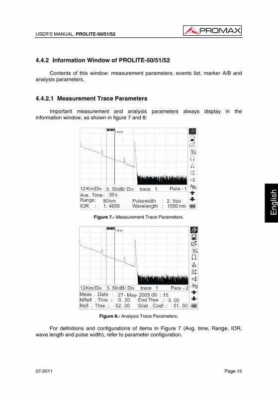
USER’S MANUAL. PROLITE-50/51/52
07-2011 Page 15
Eng
lish
4.4.2 Information Window of PROLITE-50/51/52
Contents of this window: measurement parameters, events list, marker A/B and analysis parameters. 4.4.2.1 Measurement Trace Parameters
Important measurement and analysis parameters always display in the information window, as shown in figure 7 and 8:
Figure 7.- Measurement Trace Parameters.
Figure 8.- Analysis Trace Parameters.
For definitions and configurations of items in Figure 7 (Avg. time, Range, IOR, wave length and pulse width), refer to parameter configuration.
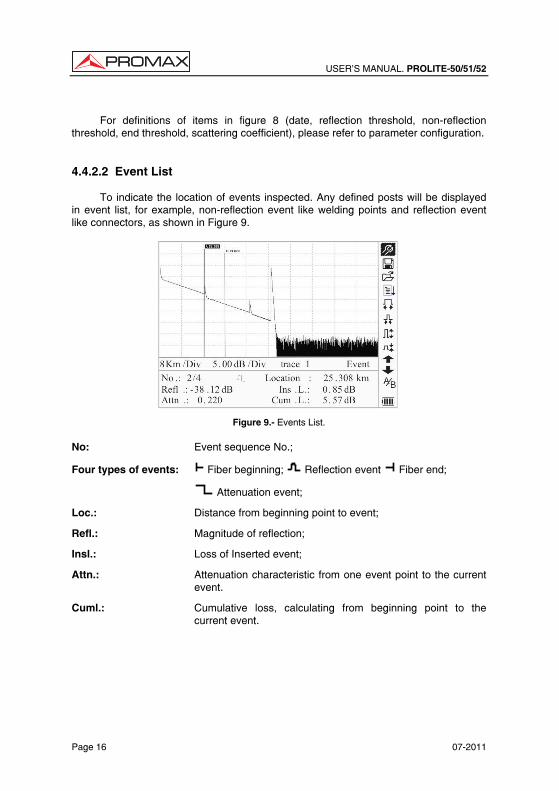
USER’S MANUAL. PROLITE-50/51/52
Page 16 07-2011
For definitions of items in figure 8 (date, reflection threshold, non-reflection
threshold, end threshold, scattering coefficient), please refer to parameter configuration. 4.4.2.2 Event List
To indicate the location of events inspected. Any defined posts will be displayed in event list, for example, non-reflection event like welding points and reflection event like connectors, as shown in Figure 9.
Figure 9.- Events List. No: Event sequence No.;
Four types of events: Fiber beginning; Reflection event Fiber end;
Attenuation event;
Loc.: Distance from beginning point to event;
Refl.: Magnitude of reflection;
Insl.: Loss of Inserted event;
Attn.: Attenuation characteristic from one event point to the current event.
Cuml.: Cumulative loss, calculating from beginning point to the current event.
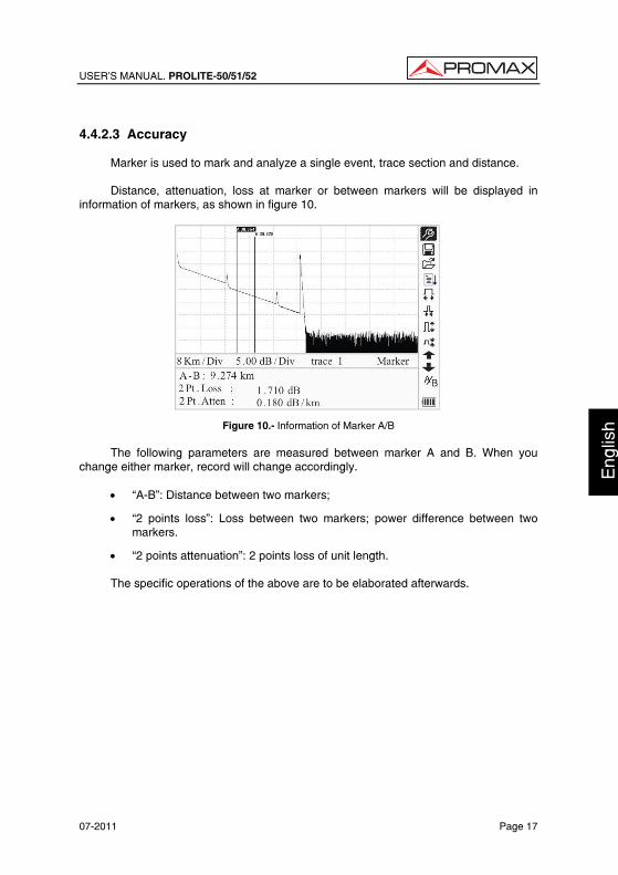
USER’S MANUAL. PROLITE-50/51/52
07-2011 Page 17
Eng
lish
4.4.2.3 Accuracy
Marker is used to mark and analyze a single event, trace section and distance.
Distance, attenuation, loss at marker or between markers will be displayed in information of markers, as shown in figure 10.
Figure 10.- Information of Marker A/B
The following parameters are measured between marker A and B. When you change either marker, record will change accordingly.
• “A-B”: Distance between two markers;
• “2 points loss”: Loss between two markers; power difference between two markers.
• “2 points attenuation”: 2 points loss of unit length.
The specific operations of the above are to be elaborated afterwards.

USER’S MANUAL. PROLITE-50/51/52
Page 18 07-2011
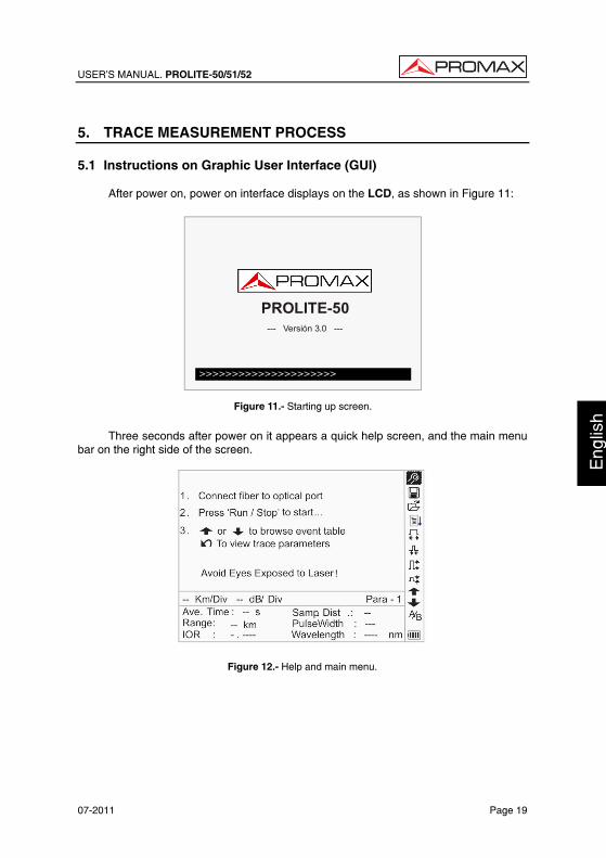
USER’S MANUAL. PROLITE-50/51/52
07-2011 Page 19
Eng
lish
5. TRACE MEASUREMENT PROCESS 5.1 Instructions on Graphic User Interface (GUI)
After power on, power on interface displays on the LCD, as shown in Figure 11:
ShinewayTechpal mOTDR- XXXX
- - - Ver si on 3. 0 - - -
>>>>>>>>>>>>>>>>>>>>>
PROLITE-50--- Versión 3.0 ---
Figure 11.- Starting up screen.
Three seconds after power on it appears a quick help screen, and the main menu
bar on the right side of the screen.
Figure 12.- Help and main menu.
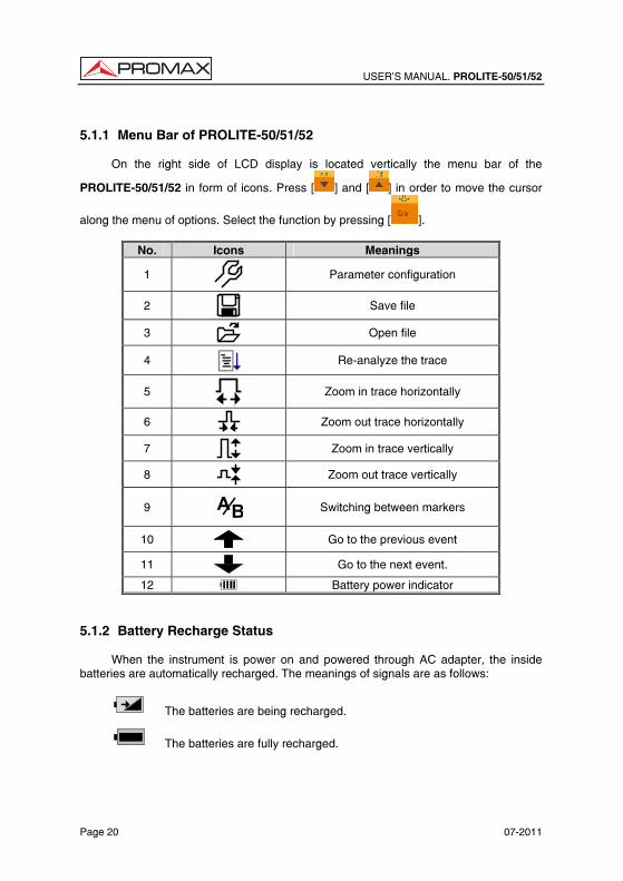
USER’S MANUAL. PROLITE-50/51/52
Page 20 07-2011
5.1.1 Menu Bar of PROLITE-50/51/52
On the right side of LCD display is located vertically the menu bar of the
PROLITE-50/51/52 in form of icons. Press [ ] and [ ] in order to move the cursor
along the menu of options. Select the function by pressing [ ].
No. Icons Meanings
1
Parameter configuration
2
Save file
3
Open file
4
Re-analyze the trace
5
Zoom in trace horizontally
6
Zoom out trace horizontally
7
Zoom in trace vertically
8
Zoom out trace vertically
9 BA
Switching between markers
10
Go to the previous event
11
Go to the next event.
12 Battery power indicator 5.1.2 Battery Recharge Status
When the instrument is power on and powered through AC adapter, the inside batteries are automatically recharged. The meanings of signals are as follows:
The batteries are being recharged.
The batteries are fully recharged.
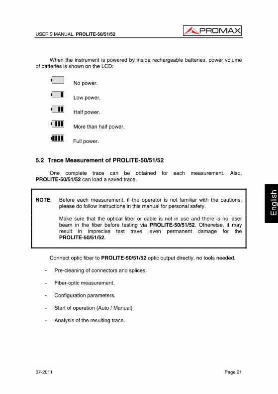
USER’S MANUAL. PROLITE-50/51/52
07-2011 Page 21
Eng
lish
When the instrument is powered by inside rechargeable batteries, power volume
of batteries is shown on the LCD:
No power.
Low power.
Half power.
More than half power.
Full power. 5.2 Trace Measurement of PROLITE-50/51/52
One complete trace can be obtained for each measurement. Also, PROLITE-50/51/52 can load a saved trace.
NOTE: Before each measurement, if the operator is not familiar with the cautions,
please do follow instructions in this manual for personal safety. Make sure that the optical fiber or cable is not in use and there is no laser
beam in the fiber before testing via PROLITE-50/51/52. Otherwise, it may result in imprecise test trave, even permanent damage for the PROLITE-50/51/52.
Connect optic fiber to PROLITE-50/51/52 optic output directly, no tools needed.
- Pre-cleaning of connectors and splices.
- Fiber-optic measurement.
- Configuration parameters.
- Start of operation (Auto / Manual)
- Analysis of the resulting trace.
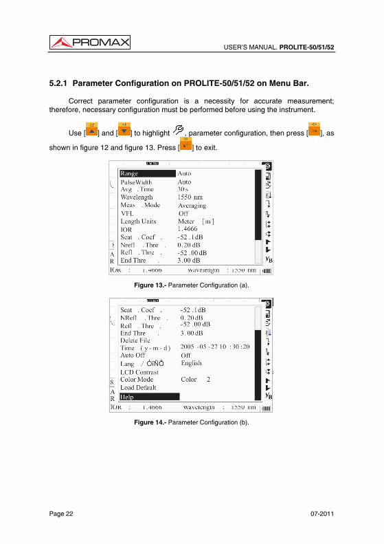
USER’S MANUAL. PROLITE-50/51/52
Page 22 07-2011
5.2.1 Parameter Configuration on PROLITE-50/51/52 on Menu Bar.
Correct parameter configuration is a necessity for accurate measurement; therefore, necessary configuration must be performed before using the instrument.
Use [ ] and [ ] to highlight , parameter configuration, then press [ ], as
shown in figure 12 and figure 13. Press [ ] to exit.
Figure 13.- Parameter Configuration (a).
Figure 14.- Parameter Configuration (b).
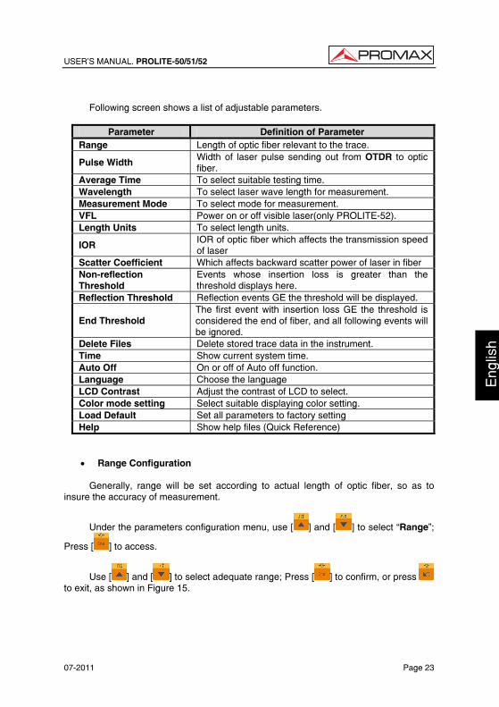
USER’S MANUAL. PROLITE-50/51/52
07-2011 Page 23
Eng
lish
Following screen shows a list of adjustable parameters.
Parameter Definition of Parameter
Range Length of optic fiber relevant to the trace.
Pulse Width Width of laser pulse sending out from OTDR to optic fiber.
Average Time To select suitable testing time. Wavelength To select laser wave length for measurement. Measurement Mode To select mode for measurement. VFL Power on or off visible laser(only PROLITE-52). Length Units To select length units.
IOR IOR of optic fiber which affects the transmission speed of laser
Scatter Coefficient Which affects backward scatter power of laser in fiber Non-reflection Threshold
Events whose insertion loss is greater than the threshold displays here.
Reflection Threshold Reflection events GE the threshold will be displayed.
End Threshold The first event with insertion loss GE the threshold is considered the end of fiber, and all following events will be ignored.
Delete Files Delete stored trace data in the instrument. Time Show current system time. Auto Off On or off of Auto off function. Language Choose the language LCD Contrast Adjust the contrast of LCD to select. Color mode setting Select suitable displaying color setting. Load Default Set all parameters to factory setting Help Show help files (Quick Reference)
• Range Configuration
Generally, range will be set according to actual length of optic fiber, so as to insure the accuracy of measurement.
Under the parameters configuration menu, use [ ] and [ ] to select “Range”;
Press [ ] to access.
Use [ ] and [ ] to select adequate range; Press [ ] to confirm, or press to exit, as shown in Figure 15.
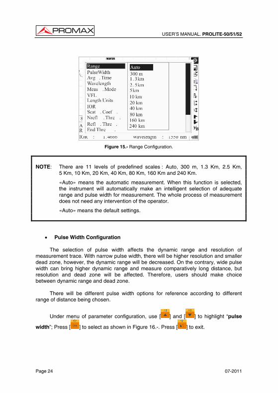
USER’S MANUAL. PROLITE-50/51/52
Page 24 07-2011
Figure 15.- Range Configuration.
NOTE: There are 11 levels of predefined scales : Auto, 300 m, 1.3 Km, 2.5 Km,
5 Km, 10 Km, 20 Km, 40 Km, 80 Km, 160 Km and 240 Km.
«Auto» means the automatic measurement. When this function is selected, the instrument will automatically make an intelligent selection of adequate range and pulse width for measurement. The whole process of measurement does not need any intervention of the operator.
«Auto» means the default settings.
• Pulse Width Configuration
The selection of pulse width affects the dynamic range and resolution of measurement trace. With narrow pulse width, there will be higher resolution and smaller dead zone, however, the dynamic range will be decreased. On the contrary, wide pulse width can bring higher dynamic range and measure comparatively long distance, but resolution and dead zone will be affected. Therefore, users should make choice between dynamic range and dead zone.
There will be different pulse width options for reference according to different range of distance being chosen.
Under menu of parameter configuration, use [ ] and [ ] to highlight “pulse
width”; Press [ ] to select as shown in Figure 16.-. Press [ ] to exit.
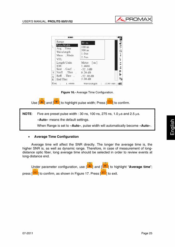
USER’S MANUAL. PROLITE-50/51/52
07-2011 Page 25
Eng
lish
Figure 16.- Average Time Configuration.
Use [ ] and [ ] to highlight pulse width; Press [ ] to confirm.
NOTE: Five are preset pulse width : 30 ns, 100 ns, 275 ns, 1.0 µs and 2.5 µs.
«Auto» means the default settings.
When Range is set to «Auto», pulse width will automatically become «Auto».
• Average Time Configuration
Average time will affect the SNR directly. The longer the average time is, the
higher SNR is, as well as dynamic range. Therefore, in case of measurement of long-distance optic fiber, long average time should be selected in order to review events at long-distance end.
Under parameter configuration, use [ ] and [ ] to highlight “Average time”;
press [ ] to confirm, as shown in Figure 17. Press [ ] to exit.
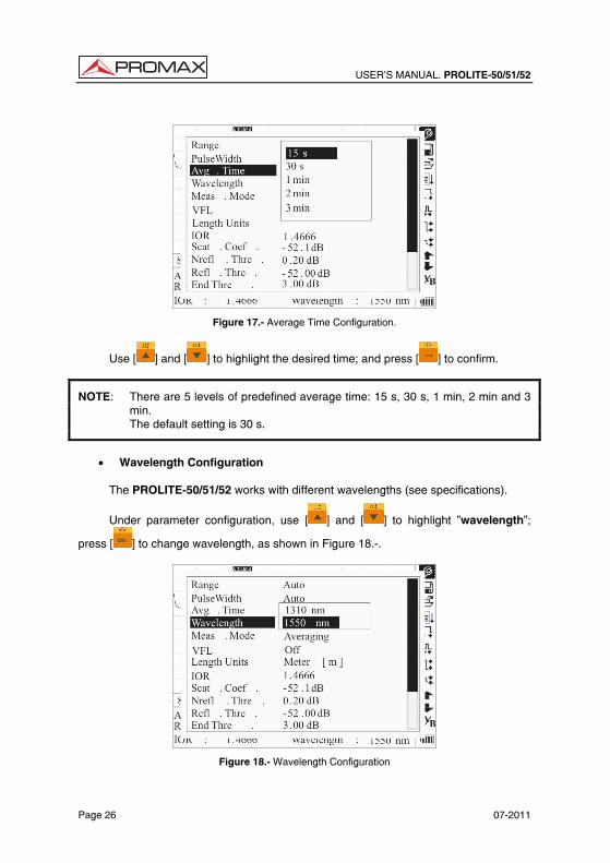
USER’S MANUAL. PROLITE-50/51/52
Page 26 07-2011
Figure 17.- Average Time Configuration.
Use [ ] and [ ] to highlight the desired time; and press [ ] to confirm.
NOTE: There are 5 levels of predefined average time: 15 s, 30 s, 1 min, 2 min and 3 min.
The default setting is 30 s.
• Wavelength Configuration
The PROLITE-50/51/52 works with different wavelengths (see specifications).
Under parameter configuration, use [ ] and [ ] to highlight ”wavelength”;
press [ ] to change wavelength, as shown in Figure 18.-.
Figure 18.- Wavelength Configuration
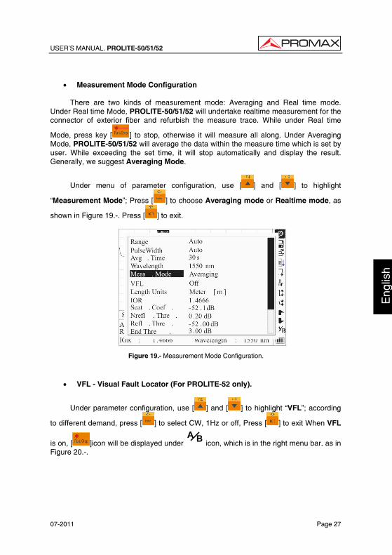
USER’S MANUAL. PROLITE-50/51/52
07-2011 Page 27
Eng
lish
• Measurement Mode Configuration
There are two kinds of measurement mode: Averaging and Real time mode.
Under Real time Mode, PROLITE-50/51/52 will undertake realtime measurement for the connector of exterior fiber and refurbish the measure trace. While under Real time
Mode, press key [ ] to stop, otherwise it will measure all along. Under Averaging Mode, PROLITE-50/51/52 will average the data within the measure time which is set by user. While exceeding the set time, it will stop automatically and display the result. Generally, we suggest Averaging Mode.
Under menu of parameter configuration, use [ ] and [ ] to highlight
“Measurement Mode”; Press [ ] to choose Averaging mode or Realtime mode, as
shown in Figure 19.-. Press [ ] to exit.
Figure 19.- Measurement Mode Configuration.
• VFL - Visual Fault Locator (For PROLITE-52 only).
Under parameter configuration, use [ ] and [ ] to highlight “VFL”; according
to different demand, press [ ] to select CW, 1Hz or off, Press [ ] to exit When VFL
is on, [ ]icon will be displayed under BA icon, which is in the right menu bar. as in
Figure 20.-.
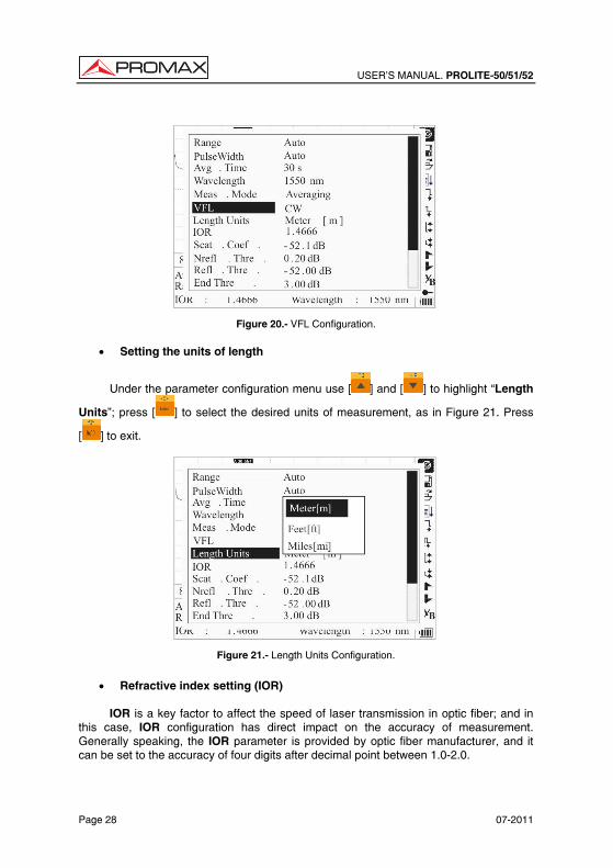
USER’S MANUAL. PROLITE-50/51/52
Page 28 07-2011
Figure 20.- VFL Configuration.
• Setting the units of length
Under the parameter configuration menu use [ ] and [ ] to highlight “Length
Units”; press [ ] to select the desired units of measurement, as in Figure 21. Press
[ ] to exit.
Figure 21.- Length Units Configuration.
• Refractive index setting (IOR)
IOR is a key factor to affect the speed of laser transmission in optic fiber; and in
this case, IOR configuration has direct impact on the accuracy of measurement. Generally speaking, the IOR parameter is provided by optic fiber manufacturer, and it can be set to the accuracy of four digits after decimal point between 1.0-2.0.
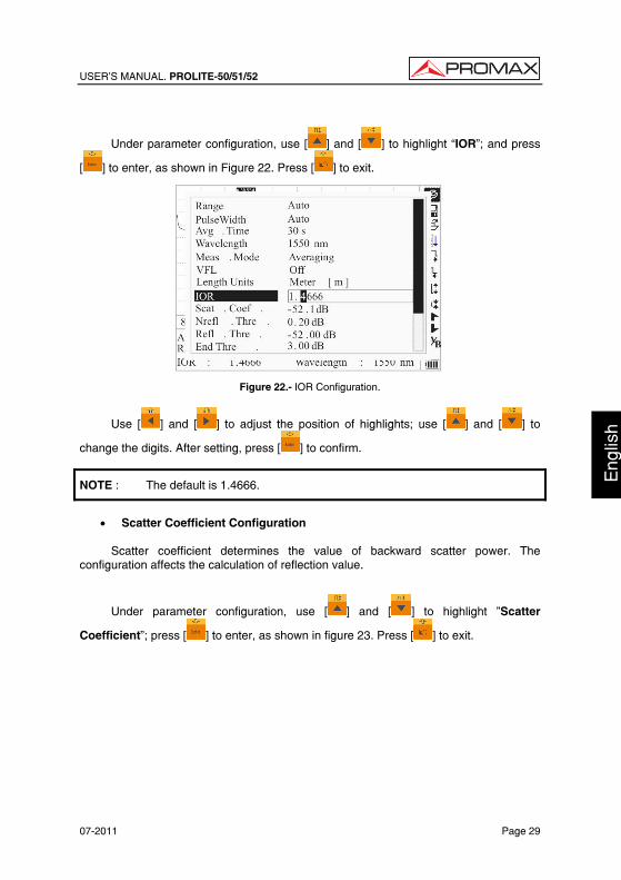
USER’S MANUAL. PROLITE-50/51/52
07-2011 Page 29
Eng
lish
Under parameter configuration, use [ ] and [ ] to highlight “IOR”; and press
[ ] to enter, as shown in Figure 22. Press [ ] to exit.
Figure 22.- IOR Configuration.
Use [ ] and [ ] to adjust the position of highlights; use [ ] and [ ] to
change the digits. After setting, press [ ] to confirm.
NOTE : The default is 1.4666.
• Scatter Coefficient Configuration
Scatter coefficient determines the value of backward scatter power. The
configuration affects the calculation of reflection value.
Under parameter configuration, use [ ] and [ ] to highlight ”Scatter
Coefficient”; press [ ] to enter, as shown in figure 23. Press [ ] to exit.
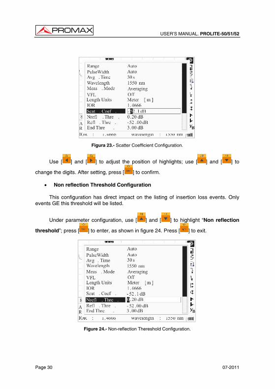
USER’S MANUAL. PROLITE-50/51/52
Page 30 07-2011
Figura 23.- Scatter Coefficient Configuration.
Use [ ] and [ ] to adjust the position of highlights; use [ ] and [ ] to
change the digits. After setting, press [ ] to confirm.
• Non reflection Threshold Configuration
This configuration has direct impact on the listing of insertion loss events. Only events GE this threshold will be listed.
Under parameter configuration, use [ ] and [ ] to highlight “Non reflection
threshold”; press [ ] to enter, as shown in figure 24. Press [ ] to exit.
Figure 24.- Non-reflection Thereshold Configuration.
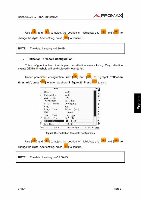
USER’S MANUAL. PROLITE-50/51/52
07-2011 Page 31
Eng
lish
Use [ ] and [ ] to adjust the position of highlights; use [ ] and [ ] to
change the digits. After setting, press [ ] to confirm.
NOTE: The default setting is 0.20 dB.
• Reflection Threshold Configuration
This configuration has direct impact on reflection events listing. Only reflection
events GE this threshold will be displayed in events list.
Under parameter configuration, use [ ] and [ ] to highlight “reflection
threshold”; press [ ] to enter, as shown in figure 25. Press [ ] to exit.
Figure 25.- Reflection Threshold Configuration
Use [ ] and [ ] to adjust the position of highlights; use [ ] and [ ] to
change the digits. After setting, press [ ] to confirm.
NOTE: The default setting is —52.00 dB.
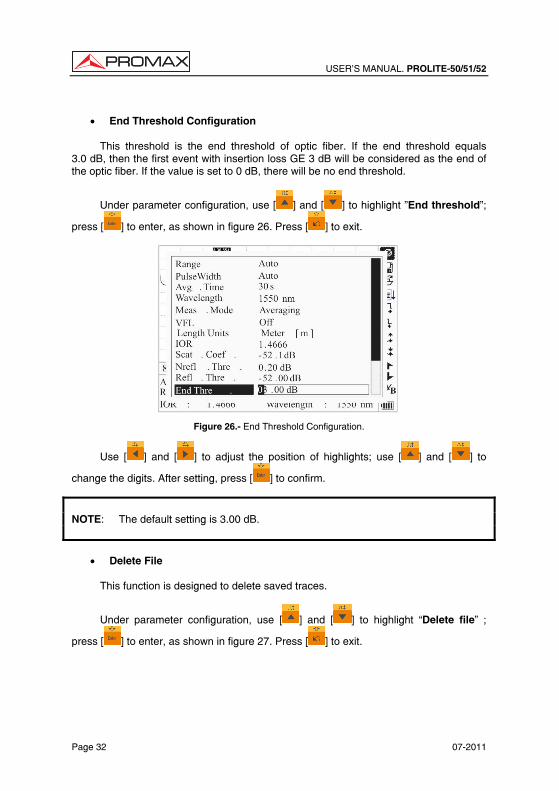
USER’S MANUAL. PROLITE-50/51/52
Page 32 07-2011
• End Threshold Configuration
This threshold is the end threshold of optic fiber. If the end threshold equals
3.0 dB, then the first event with insertion loss GE 3 dB will be considered as the end of the optic fiber. If the value is set to 0 dB, there will be no end threshold.
Under parameter configuration, use [ ] and [ ] to highlight ”End threshold”;
press [ ] to enter, as shown in figure 26. Press [ ] to exit.
Figure 26.- End Threshold Configuration.
Use [ ] and [ ] to adjust the position of highlights; use [ ] and [ ] to
change the digits. After setting, press [ ] to confirm.
NOTE: The default setting is 3.00 dB.
• Delete File
This function is designed to delete saved traces.
Under parameter configuration, use [ ] and [ ] to highlight “Delete file” ;
press [ ] to enter, as shown in figure 27. Press [ ] to exit.
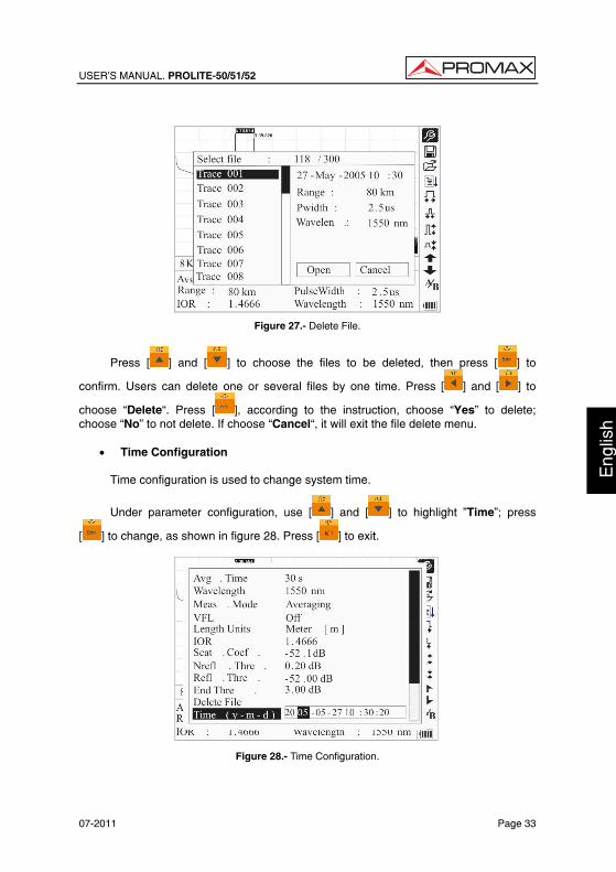
USER’S MANUAL. PROLITE-50/51/52
07-2011 Page 33
Eng
lish
Figure 27.- Delete File.
Press [ ] and [ ] to choose the files to be deleted, then press [ ] to
confirm. Users can delete one or several files by one time. Press [ ] and [ ] to
choose “Delete“. Press [ ], according to the instruction, choose “Yes” to delete; choose “No” to not delete. If choose “Cancel“, it will exit the file delete menu.
• Time Configuration
Time configuration is used to change system time.
Under parameter configuration, use [ ] and [ ] to highlight ”Time”; press
[ ] to change, as shown in figure 28. Press [ ] to exit.
Figure 28.- Time Configuration.
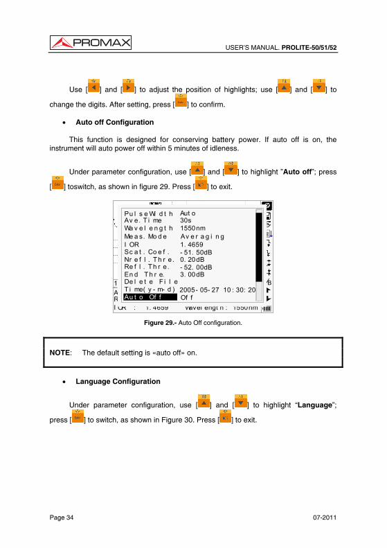
USER’S MANUAL. PROLITE-50/51/52
Page 34 07-2011
Use [ ] and [ ] to adjust the position of highlights; use [ ] and [ ] to
change the digits. After setting, press [ ] to confirm.
• Auto off Configuration
This function is designed for conserving battery power. If auto off is on, the instrument will auto power off within 5 minutes of idleness.
Under parameter configuration, use [ ] and [ ] to highlight ”Auto off”; press
[ ] toswitch, as shown in figure 29. Press [ ] to exit.
1. 4659 1550nm
Ave. Ti me:Range:I OR : Wavel engt h :
12Km/ Di v 3.50dB/Div t race1.t rc 15:20 BA
2500ns
Wa v e l e n g t h 1550nm
Pu l s e Wi d t h Aut oAv e. T i me 30s
I OR 1. 4659
Nr e f l . T h r e. 0. 20dBRe f l . Th r e. - 52. 00dBEn d T h r e. 3. 00dB
Sc a t . Co e f . - 51. 50dB
Av e r a g i n gMe a s. Mo d e
De l e t e F i l eT i me( y - m- d ) 2005- 05- 27 10 : 30: 20Au t o Of f Of f
Figure 29.- Auto Off configuration.
NOTE: The default setting is «auto off» on.
• Language Configuration
Under parameter configuration, use [ ] and [ ] to highlight “Language”;
press [ ] to switch, as shown in Figure 30. Press [ ] to exit.
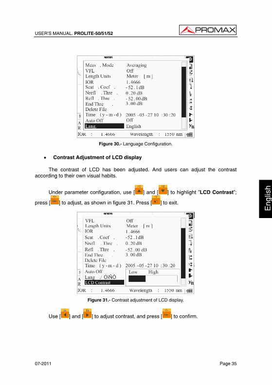
USER’S MANUAL. PROLITE-50/51/52
07-2011 Page 35
Eng
lish
Figure 30.- Language Configuration.
• Contrast Adjustment of LCD display
The contrast of LCD has been adjusted. And users can adjust the contrast
according to their own visual habits.
Under parameter configuration, use [ ] and [ ] to highlight ”LCD Contrast”;
press [ ] to adjust, as shown in figure 31. Press [ ] to exit.
Figure 31.- Contrast adjustment of LCD display.
Use [ ] and [ ] to adjust contrast, and press [ ] to confirm.
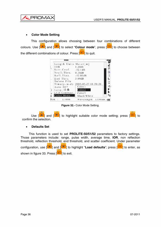
USER’S MANUAL. PROLITE-50/51/52
Page 36 07-2011
• Color Mode Setting
This configuration allows choosing between four combinations of different
colours. Use [ ] and [ ] to select “Colour mode”, press [ ] to choose between
the different combinations of colour. Press [ ] to quit.
Figure 32.- Color Mode Setting.
Use [ ] and [ ] to highlight suitable color mode setting; press [ ] to confirm the selection.
• Defaults Set
This function is used to set PROLITE-50/51/52 parameters to factory settings.
Those parameters include: range, pulse width, average time, IOR, non reflection threshold, reflection threshold, end threshold, and scatter coefficient. Under parameter
configuration, use [ ] and [ ] to highlight “Load defaults”; press [ ] to enter, as
shown in figure 33. Press [ ] to exit.
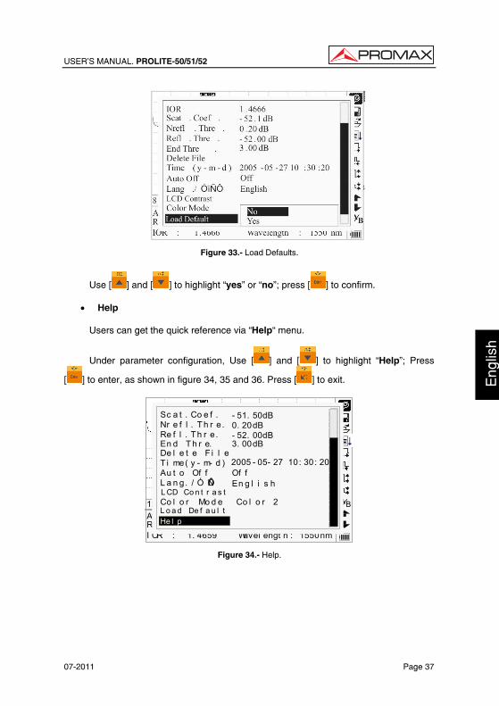
USER’S MANUAL. PROLITE-50/51/52
07-2011 Page 37
Eng
lish
Figure 33.- Load Defaults.
Use [ ] and [ ] to highlight “yes” or “no”; press [ ] to confirm.
• Help
Users can get the quick reference via “Help“ menu.
Under parameter configuration, Use [ ] and [ ] to highlight “Help”; Press
[ ] to enter, as shown in figure 34, 35 and 36. Press [ ] to exit.
1. 4659 1550nm
Ave. Ti me:Range:I OR : Wavel engt h :
12Km/ Di v 3.50dB/Div t race1.t rc 15: 20 BA
Nr e f l . T h r e. 0. 20dBRe f l . Th r e. - 52. 00dBEn d T h r e. 3. 00dB
Sc a t . Co e f . - 51. 50dB
De l e t e F i l eT i me( y - m- d ) 2005 - 05- 27 10: 30: 20Au t o Of f Of fL a n g. / Ó ïÑÔ En g l i s hL CD Co n t r a s t
L o a d De f a u l tHe l p
Co l o r Mo d e Co l o r 2
Figure 34.- Help.
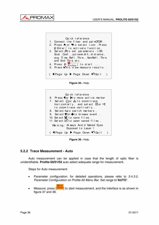
USER’S MANUAL. PROLITE-50/51/52
Page 38 07-2011
Qui ck r ef er ence
( Page Up Page Down Qui t )
1. Connect t he f i ber and pal mOTDR .2. Pr ess or t o sel ect i con , Pr ess
¡® Ent er ¡̄ t o act i vat e f unct i on .3. Sel ect t o set par amet er s : I OR, Scat . Coef . , pul sewi dt h , di st ance , avg. Ti me, Ref l . Thr e. , NonRef l . Thr e and End Thr e et c .4. Pr ess ¡® ¡̄ t o st ar t . . .Run/Stop5. Pr ess t o vi ew measur e r esul t s .
Figure 35.- Help.
Qui ck r ef er ence
War ni ng : Al ways Avoi d Naked Eyes Exposed t o Laser !
( Page Up Page Down Qui t )
7. Sel ect or t o zoom t r ace
t o zoom t r ace ver t i cal l y . hor i zont al l y , and sel ect or
6. Pr ess or t o move act i ve mar ker
8. Sel ect t o swi t ch mar ker s . BA
9. Sel ect or t o br owse event .10. Sel ect t o save f i l es .11. Sel ect t o open saved f i l es .
Figure 36.- Help.
5.2.2 Trace Measurement - Auto
Auto measurement can be applied in case that the length of optic fiber is unidentifiable. Prolite-50/51/52 auto select adequate range for measurement.
Steps for Auto measurement:
• Parameter configuration: for detailed operations, please refer to 3.4.3.2, Parameter Configuration on Prolite-50 Menu Bar. Set range to”AUTO”.
• Measure: press [ ] to start measurement, and the interface is as shown in figure 37 and 38.
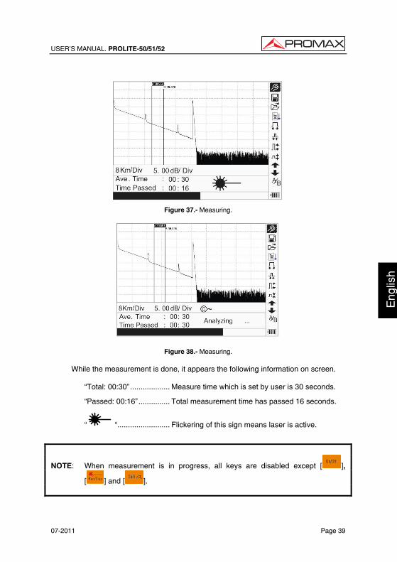
USER’S MANUAL. PROLITE-50/51/52
07-2011 Page 39
Eng
lish
Figure 37.- Measuring.
Figure 38.- Measuring.
While the measurement is done, it appears the following information on screen.
“Total: 00:30”................... Measure time which is set by user is 30 seconds.
“Passed: 00:16”............... Total measurement time has passed 16 seconds.
“ “......................... Flickering of this sign means laser is active.
NOTE: When measurement is in progress, all keys are disabled except [ ],
[ ] and [ ].
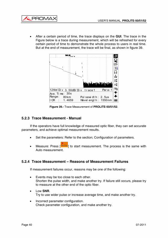
USER’S MANUAL. PROLITE-50/51/52
Page 40 07-2011
• After a certain period of time, the trace displays on the GUI. The trace in the
Figure below is a trace during measurement, which will be refreshed for every certain period of time to demonstrate the whole process to users in real time. But at the end of measurement, the trace will be final, as shown in figure 39.
BA
30s80km1. 4659
2. 5us1550nm
Ave. Ti me:Range:I OR :
Pul sewi dt h :Wavel engt h :
12Km/ Di v 3. 50dB/ Di v t r ace 1 Par a- 1
Figure 39.- Trace Measurement of PROLITE-50/51/52. 5.2.3 Trace Measurement - Manual
If the operators have full knowledge of measured optic fiber, they can set accurate parameters, and achieve optimal measurement results.
• Set the parameters: Refer to the section; Configuration of parameters.
• Measure: Press [ ] to start measurement. The process is the same with Auto measurement.
5.2.4 Trace Measurement — Reasons of Measurement Failures
If measurement failures occur, reasons may be one of the following:
• Events may be too close to each other. Shorten the pulse width, and make another try. If failure still occurs, please try to measure at the other end of the optic fiber.
• Low SNR. Try to use wider pulse or increase average time, and make another try.
• Incorrect parameter configuration. Check parameter configuration, and make another try.
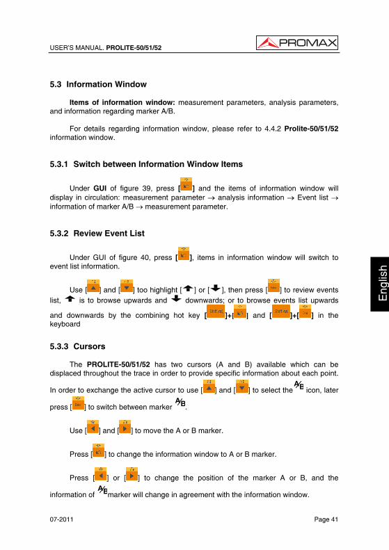
USER’S MANUAL. PROLITE-50/51/52
07-2011 Page 41
Eng
lish
5.3 Information Window
Items of information window: measurement parameters, analysis parameters, and information regarding marker A/B.
For details regarding information window, please refer to 4.4.2 Prolite-50/51/52 information window. 5.3.1 Switch between Information Window Items
Under GUI of figure 39, press [ ] and the items of information window will display in circulation: measurement parameter → analysis information → Event list → information of marker A/B → measurement parameter. 5.3.2 Review Event List
Under GUI of figure 40, press [ ], items in information window will switch to event list information.
Use [ ] and [ ] too highlight [ ] or [ ], then press [ ] to review events list, is to browse upwards and downwards; or to browse events list upwards
and downwards by the combining hot key [ ]+[ ] and [ ]+[ ] in the keyboard
5.3.3 Cursors
The PROLITE-50/51/52 has two cursors (A and B) available which can be displaced throughout the trace in order to provide specific information about each point.
In order to exchange the active cursor to use [ ] and [ ] to select the BA icon, later
press [ ] to switch between marker BA.
Use [ ] and [ ] to move the A or B marker.
Press [ ] to change the information window to A or B marker.
Press [ ] or [ ] to change the position of the marker A or B, and the
information of BAmarker will change in agreement with the information window.
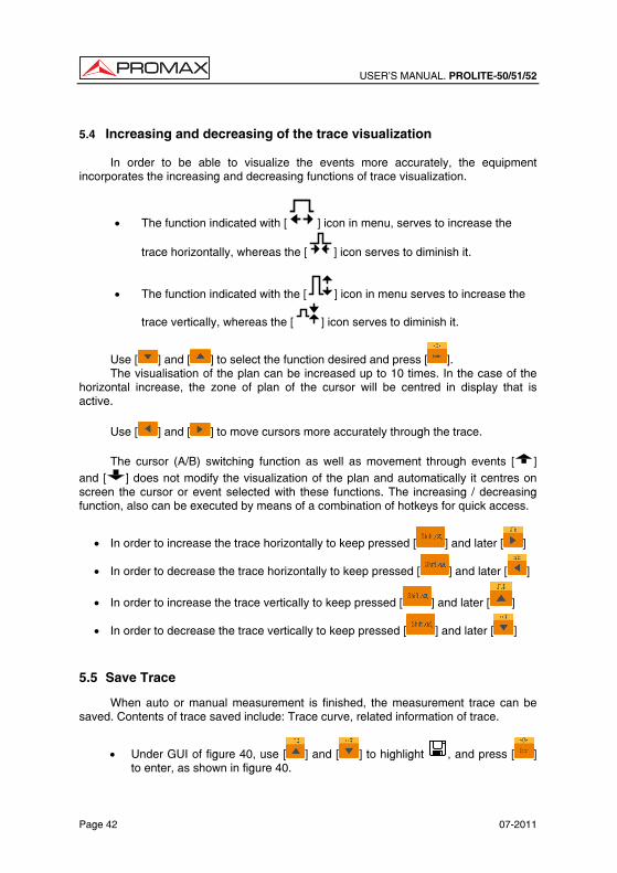
USER’S MANUAL. PROLITE-50/51/52
Page 42 07-2011
5.4 Increasing and decreasing of the trace visualization
In order to be able to visualize the events more accurately, the equipment incorporates the increasing and decreasing functions of trace visualization.
• The function indicated with [ ] icon in menu, serves to increase the
trace horizontally, whereas the [ ] icon serves to diminish it.
• The function indicated with the [ ] icon in menu serves to increase the
trace vertically, whereas the [ ] icon serves to diminish it.
Use [ ] and [ ] to select the function desired and press [ ]. The visualisation of the plan can be increased up to 10 times. In the case of the
horizontal increase, the zone of plan of the cursor will be centred in display that is active.
Use [ ] and [ ] to move cursors more accurately through the trace.
The cursor (A/B) switching function as well as movement through events [ ] and [ ] does not modify the visualization of the plan and automatically it centres on screen the cursor or event selected with these functions. The increasing / decreasing function, also can be executed by means of a combination of hotkeys for quick access.
• In order to increase the trace horizontally to keep pressed [ ] and later [ ]
• In order to decrease the trace horizontally to keep pressed [ ] and later [ ]
• In order to increase the trace vertically to keep pressed [ ] and later [ ]
• In order to decrease the trace vertically to keep pressed [ ] and later [ ]
5.5 Save Trace
When auto or manual measurement is finished, the measurement trace can be saved. Contents of trace saved include: Trace curve, related information of trace.
• Under GUI of figure 40, use [ ] and [ ] to highlight , and press [ ] to enter, as shown in figure 40.
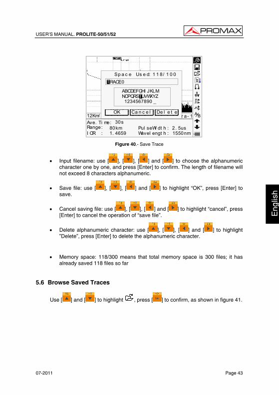
USER’S MANUAL. PROLITE-50/51/52
07-2011 Page 43
Eng
lish
30s80km1. 4659
2. 5us1550nm
Ave. Ti me:Range:I OR :
Pul seWi dt h :Wavel engt h :
12Km/ Di v 3.50dB/Div t race1.t rc Par a- 1Ca n c e l
ABCDEFGHI JKLMNOPQRSTUVWXYZ 1234567890 _
Sp a c e Us e d: 1 1 8/ 1 0 0
OK De l e t e
RACE0T
T
BA
Figure 40.- Save Trace
• Input filename: use [ ], [ ], [ ] and [ ] to choose the alphanumeric character one by one, and press [Enter] to confirm. The length of filename will not exceed 8 characters alphanumeric.
• Save file: use [ ], [ ], [ ] and [ ] to highlight “OK”, press [Enter] to save.
• Cancel saving file: use [ ], [ ], [ ] and [ ] to highlight “cancel”, press [Enter] to cancel the operation of “save file”.
• Delete alphanumeric character: use [ ], [ ], [ ] and [ ] to highlight ”Delete”, press [Enter] to delete the alphanumeric character.
• Memory space: 118/300 means that total memory space is 300 files; it has already saved 118 files so far
5.6 Browse Saved Traces
Use [ ] and [ ] to highlight , press [ ] to confirm, as shown in figure 41.
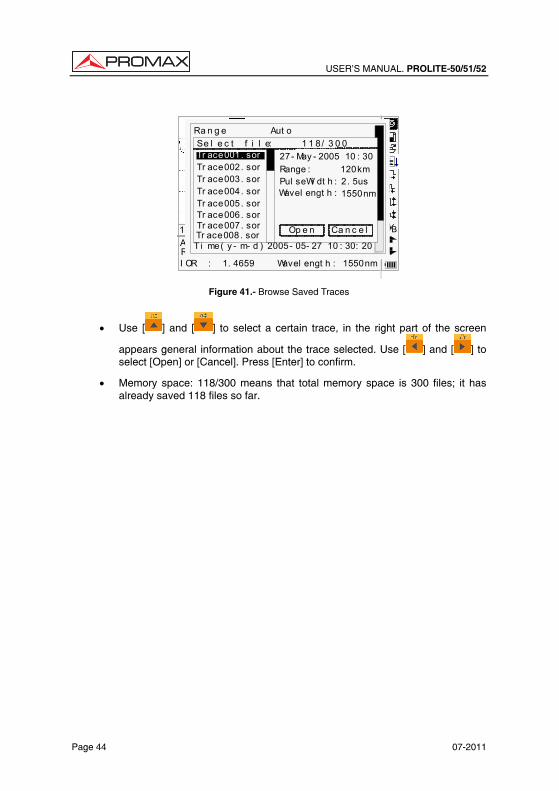
USER’S MANUAL. PROLITE-50/51/52
Page 44 07-2011
30s80km1. 4659
2.5us1550nm
Ave. Ti me:Range :I OR :
PulseW idth:Wavel engt h :
12Km/ Di v 3.50dB/ Div t race1.t rc 15:20 BA30s
80km 2500ns
Ra n g e
Wa v e l e n g t h 1550nm
Pu l s e Wi d t h Aut oAv e. T i me 30s
I OR 1. 4659
Nr e f l . T h r e. 0. 20dBRe f l . Th r e. - 52. 00dBEn d Th r e. 3. 00dB
Sc a t . Co e f . - 51. 50dB
Av e r a g i n gMe a s . Mo d e
De l e t e F i l eT i me( y - m- d ) 2005- 05- 27 10 : 30: 20
Aut oSe l e c t f i l e: 1 1 8/ 3 0 0Tr ace001. sorTr ace002. sorTr ace003. sorTr ace004. sorTr ace005. sor
Ca n c e lOp e nTr ace006. sorTr ace007. sorTr ace008. sor
27- May - 2005 10 : 30Range : 120kmPul seWi dt h : 2. 5usWavel engt h : 1550nm
Figure 41.- Browse Saved Traces
• Use [ ] and [ ] to select a certain trace, in the right part of the screen
appears general information about the trace selected. Use [ ] and [ ] to select [Open] or [Cancel]. Press [Enter] to confirm.
• Memory space: 118/300 means that total memory space is 300 files; it has already saved 118 files so far.
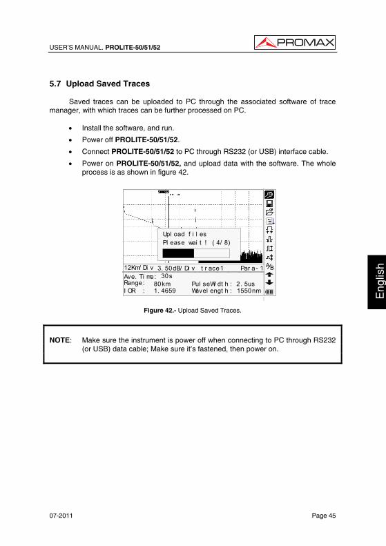
USER’S MANUAL. PROLITE-50/51/52
07-2011 Page 45
Eng
lish
5.7 Upload Saved Traces
Saved traces can be uploaded to PC through the associated software of trace manager, with which traces can be further processed on PC.
• Install the software, and run.
• Power off PROLITE-50/51/52.
• Connect PROLITE-50/51/52 to PC through RS232 (or USB) interface cable.
• Power on PROLITE-50/51/52, and upload data with the software. The whole process is as shown in figure 42.
30s80km1. 4659
2. 5us1550nm
Ave. Ti me:Range:I OR :
Pul seWi dt h :Wavel engt h :
12Km/ Di v 3. 50dB/ Di v t r ace1 Par a- 1
Upl oad f i l esPl ease wai t ! ( 4/ 8)
BA
Figure 42.- Upload Saved Traces.
NOTE: Make sure the instrument is power off when connecting to PC through RS232
(or USB) data cable; Make sure it’s fastened, then power on.

USER’S MANUAL. PROLITE-50/51/52
Page 46 07-2011
USER’S MANUAL. PROLITE-50/51/52
07-2011 Page 47
Eng
lish
6. MAINTENANCE 6.1 Maintenance of Batteries
Battery for this instrument is rechargeable NiMH battery. All the NiMH batteries have been correctly installed and gone thorough precise debugging. Please do not open the instrument to replace batteries at discretion. • Cautions during Operation:
The following may bring auto power off of the instrument:
The instrument will be auto power off when there is insufficient power during operation and low power will be shown on the LCD.
If unused for a long time and cause insufficient power, the instrument will be power off several seconds after powering on so as to protect the batteries in case of excessive discharging. The inside batteries should be recharged immediately through adapter.
NOTE: Notes for maintenance of batteries in the instrument: In order for the PROLITE-50/51/52 (including the batteries) to meet
specifications, the storage temperature should be within 0 °C to 40 °C. And the instruments should be stored in low humidity environments.
One rechargeable NiMH battery is inside the instrument. Do not replace the
battery by yourself. If the instrument is left unused for a long time (idle for over 2 months), it is
recommended to recharge the battery every other month.
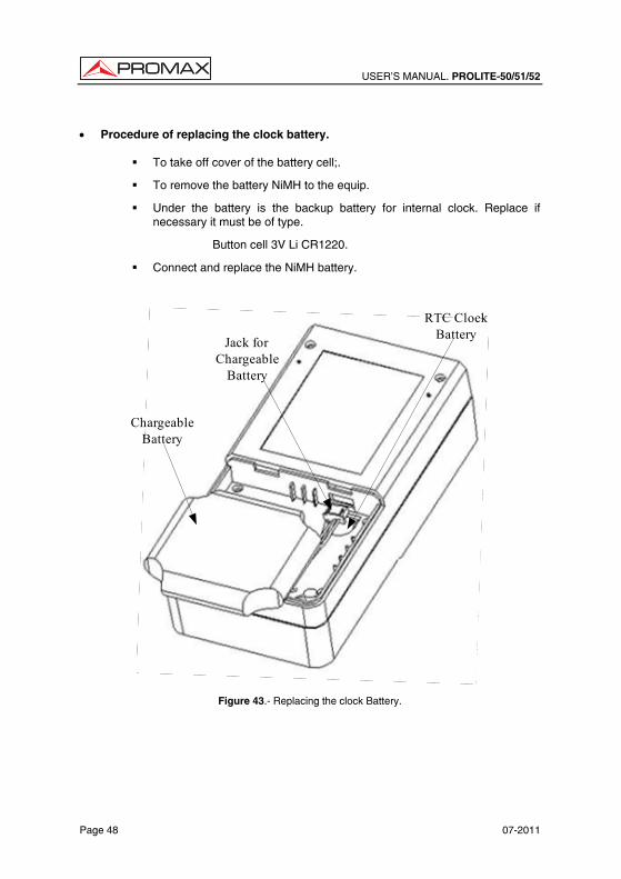
USER’S MANUAL. PROLITE-50/51/52
Page 48 07-2011
• Procedure of replacing the clock battery.
To take off cover of the battery cell;.
To remove the battery NiMH to the equip.
Under the battery is the backup battery for internal clock. Replace if necessary it must be of type.
Button cell 3V Li CR1220.
Connect and replace the NiMH battery.
RTC Clock Battery
Chargeable Battery
Jack for Chargeable
Battery
Figure 43.- Replacing the clock Battery.
USER’S MANUAL. PROLITE-50/51/52
07-2011 Page 49
Eng
lish
6.2 Cleaning of Interfaces
Interfaces must be kept clean. Special alcohol may be used to clean optic output. Always replace protective dust caps when the unit is not being used, and keep the protective dust caps clean.
In addition, flanges must be kept clean periodically, • Effects of Cleaning Interfaces and Connectors
The diameter of optic core is 9um, and diameter of dust and other particulates ranges from 1/100 to 1/1/10 um. Comparatively speaking, the size of dust and other particulates can cover part of optic end and therefore degrade the performance of the instrument. In addition, power density may burn dust into optic fiver and induce further damage (for example, 0dBm optic power may produce about 16000000 W/m*m power density in single mode fiber). In this case, measurement will be inaccurate and irreversible.
• Safety Instructions to be Followed before Cleaning
a) Make sure the instrument is power off when cleaning.
b) Any operations contradict to the instructions may result in dangerous laser injuries.
c) Make sure laser source is off, when clean any optic connectors.
d) When the instrument is in operation, please always avoid looking directly into optic output. Although laser radiation is invisible, it may do serious injury to eyesight.
e) Be cautious of electric shock and make sure AC power is disconnected with the instrument before cleaning. Always use dry or moistest soft cloth to clean the outside of the instrument, and never clean the inside.
f) Please do not add any accessory to optic instrument or adjust the instrument at discretion.
g) For maintenance, always go to qualified or certified professionals.
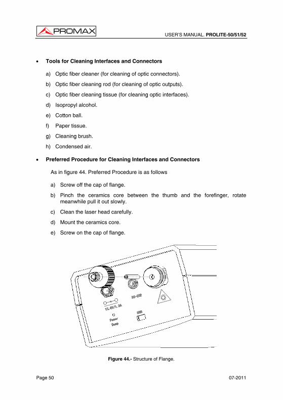
USER’S MANUAL. PROLITE-50/51/52
Page 50 07-2011
• Tools for Cleaning Interfaces and Connectors
a) Optic fiber cleaner (for cleaning of optic connectors).
b) Optic fiber cleaning rod (for cleaning of optic outputs).
c) Optic fiber cleaning tissue (for cleaning optic interfaces).
d) Isopropyl alcohol.
e) Cotton ball.
f) Paper tissue.
g) Cleaning brush.
h) Condensed air. • Preferred Procedure for Cleaning Interfaces and Connectors
As in figure 44. Preferred Procedure is as follows
a) Screw off the cap of flange.
b) Pinch the ceramics core between the thumb and the forefinger, rotate meanwhile pull it out slowly.
c) Clean the laser head carefully.
d) Mount the ceramics core.
e) Screw on the cap of flange.
Figure 44.- Structure of Flange.
USER’S MANUAL. PROLITE-50/51/52
07-2011 Page 51
Eng
lish
6.3 Calibration Requeriments
Calibration of the instrument is recommended every two years. Please contact our representatives or nearby customer service centers for proper calibration. 6.4 Cleaning Recommendations
CAUTION
To clean the cover, take care the instrument is disconnected.
CAUTION
Do not use scented hydrocarbons or chlorized solvents. Such products may attack the plastics used in the construction of the cover. The cover should be cleaned by means of a light solution of detergent and water applied with a soft cloth. Dry thoroughly before using the system again.

USER’S MANUAL. PROLITE-50/51/52
Page 52 07-2011