NSTALLATION N ANUAL N · 2019-01-31 · DETERMINE GARAGE DOOR TYPE Determine your garage door type...
20
DC-650N DC-650N DC-650N DC-650N DC-650N DC-650N DC-650N DC-650N DC-650N DC-650N DC-650N DC-650N DC-650N DC-650N DC-650N DC-650N DC-650N DC-650N DC-650N DC-650N DC-650N DC-650N DC-650N DC-650N DC-650N DC-650N DC-650N DC-650N DC-650N DC-650N DC-650N DC-650N DC-650N DC-650N DC-650N DC-650N DC-650N DC-650N DC-650N DC-650N DC-650N DC-650N DC-650N DC-650N DC-650N DC-650N DC-650N DC-650N DC-650N DC-650N DC-650N DC-650N DC-650N DC-650N DC-650N DC-650N DC-650N DC-650N DC-650N DC-650N DC-650N DC-650N DC-650N DC-650N DC-650N DC-650N DC-650N DC-650N DC-650N DC-650N DC-650N DC-650N DC-650N DC-650N DC-650N DC-650N DC-650N DC-650N DC-650N DC-650N DC-650N DC-650N DC-650N DC-650N DC-650N DC-650N DC-650N DC-650N DC-650N DC-650N DC-650N DC-650N OWNER’S & INSTALLATION MANUAL #. 8 051 167; V 01.2003
Transcript of NSTALLATION N ANUAL N · 2019-01-31 · DETERMINE GARAGE DOOR TYPE Determine your garage door type...
DC-650N DC-650N DC-650N DC-650NDC-650N DC-650N DC-650N DC-650NDC-650N DC-650N DC-650N DC-650NDC-650N DC-650N DC-650N DC-650NDC-650N DC-650N DC-650N DC-650NDC-650N DC-650N DC-650N DC-650NDC-650N DC-650N DC-650N DC-650NDC-650N DC-650N DC-650N DC-650NDC-650N DC-650N DC-650N DC-650NDC-650N DC-650N DC-650N DC-650NDC-650N DC-650N DC-650N DC-650NDC-650N DC-650N DC-650N DC-650NDC-650N DC-650N DC-650N DC-650NDC-650N DC-650N DC-650N DC-650NDC-650N DC-650N DC-650N DC-650NDC-650N DC-650N DC-650N DC-650NDC-650N DC-650N DC-650N DC-650NDC-650N DC-650N DC-650N DC-650NDC-650N DC-650N DC-650N DC-650NDC-650N DC-650N DC-650N DC-650NDC-650N DC-650N DC-650N DC-650N
DC-650N DC-650N DC-650N DC-650N
DC-650N DC-650N DC-650N DC-650N
OWNER’S & INSTALLATION MANUAL
#.
8 0
51 1
67;
V 0
1.2
003
! IMPORTANT SAFETY INSTRUCTIONS FOR INSTALLATIONWARNING – INCORRECT INSTALLATION CAN LEAD TO SEVERE INJURY FOLLOW ALL INSTALLATION INSTRUCTIONS CAREFULLY
Before installing the operator check that the door is in good mechanical condition,
and correctly balanced, and that it opens and closes properly.
• Do not use the force adjustments to compensate for a binding or sticking garage door.
Excessive force will interfere with the proper operation of the Safety Reverse System
or damage the garage door.
• Do not wear rings, watches or loose clothing while installing or servicing a garage
door operator.
• To avoid serious personal injury from entanglement, remove any ropes connected to
the garage door before installing the door operator.
• Install the remote mounted bell push button within sight of the door but away from
any moving parts and at a height of at least 1.5 metres.
• The safety reverse system test is very important. The garage door must reverse when
obstructed on closing. Failure to properly adjust the operator may result in serious
personal injury from a closing garage door. Repeat the test once a month and make
any needed adjustments (see Advanced Settings, Menu b and Menu c on page 15 of
this manual).
Installation and wiring must be in compliance with your local building and electrical codes.
• If the garage has no service entrance door then an exterior release kit MUST be fitted.
This accessory allows manual operation of the garage door from outside in case of
power failure.
• Disconnect electric power to the garage door operator before making repairs or
removing covers.
• Use the manual release lever to disengage the motor drive ONLY when the drive is
switched OFF and, if possible, when the door is fully closed.
• Examine the installation, in particular the cables, spring and mountings, for signs of
wear, damage or imbalance. Do not use if repair or adjustment is needed since a fault
in the installation or an incorrectly balanced door may cause injury.
IMPORTANT SAFETY NOTEOnly operate the door when the door is in full view, free of obstacles with no persons (particularly children) near the door. Nobody should be allowed to enter or leave the garage whilst the door is in motion.
Page 2
Page 3
Please keep this manual for future reference, repair and maintenance.
INTRODUCTIONCongratulations on the purchase of your new automatic garage door operator. It is designed to
offer you convenience, durability and quality. This operator has been factory tested to ensure
maximum quality and safety.
In order to prevent damage to the garage door or garage door operator and to comply with the
Machinery Directive it is important that this operator is fitted in accordance with these instruc-
tions.
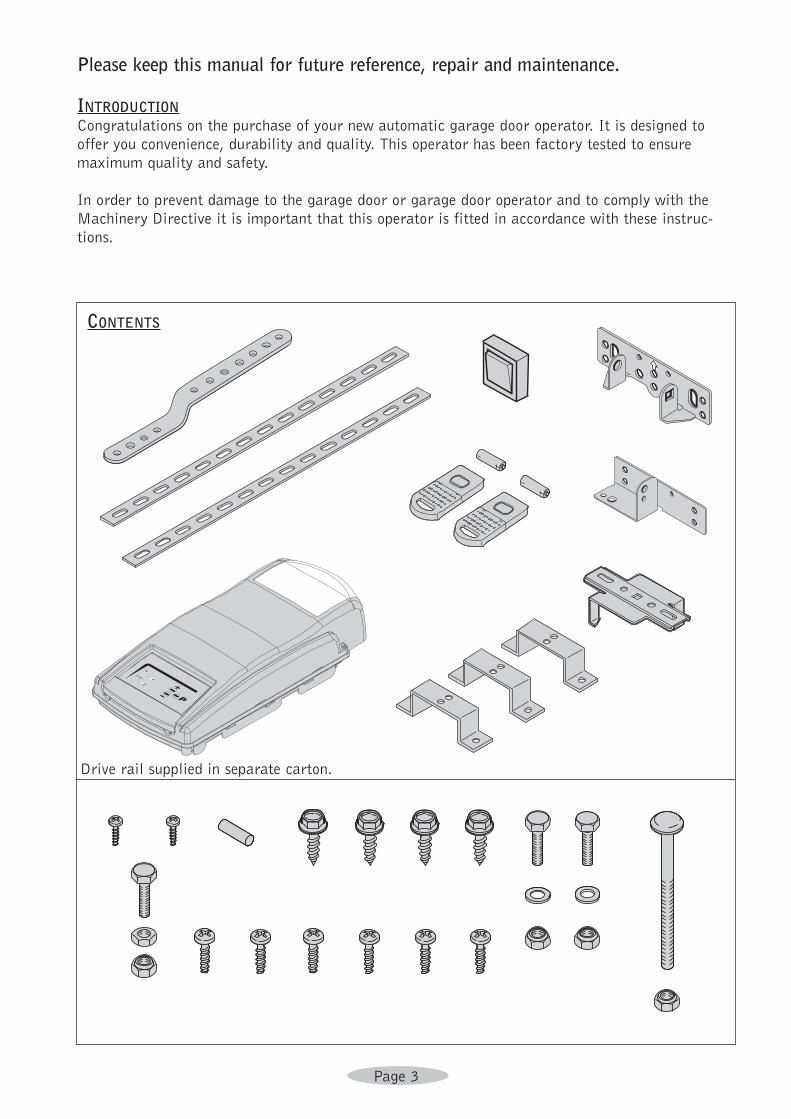
CONTENTS
Drive rail supplied in separate carton.
Page 4
SAFETY FEATURES• Automatic Door Reverse
An unmodified closing door will automatically reverse within 2 seconds if door is obstructed
by person or object.
• Automatic Time ReverseClosing door will automatically reverse if the door is not fully closed within 88 seconds.
• Safety StopOpening door will immediately stop when obstructed by person or object.
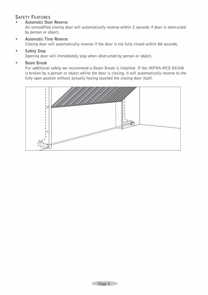
• Beam BreakFor additional safety we recommend a Beam Break is installed. If the INFRA-RED BEAM
is broken by a person or object whilst the door is closing, it will automatically reverse to the
fully open postion without actually having touched the closing door itself.
Page 5
Note: Where the operator has been specified with a 2-piece boom, please refer to the
assembly instructions for this item supplied with the boom.
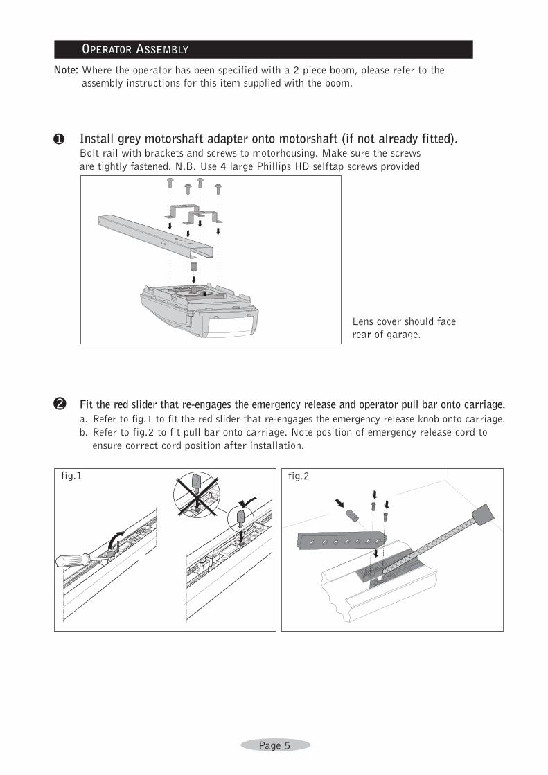
a Install grey motorshaft adapter onto motorshaft (if not already fitted).Bolt rail with brackets and screws to motorhousing. Make sure the screws
are tightly fastened. N.B. Use 4 large Phillips HD selftap screws provided
Lens cover should face
rear of garage.
2 Fit the red slider that re-engages the emergency release and operator pull bar onto carriage. a. Refer to fig.1 to fit the red slider that re-engages the emergency release knob onto carriage.
b. Refer to fig.2 to fit pull bar onto carriage. Note position of emergency release cord to
ensure correct cord position after installation.
OPERATOR ASSEMBLY
fig.1 fig.2
Page 6
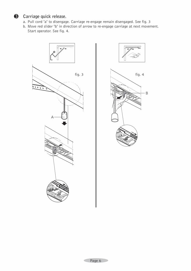
3 Carriage quick release. a. Pull cord ''a'' to disengage. Carriage re-engage remain disengaged. See fig. 3
b. Move red slider ''b'' in direction of arrow to re-engage carriage at next movement.
Start operator. See fig. 4.
fig. 3 fig. 4
A
B
Page 7
�
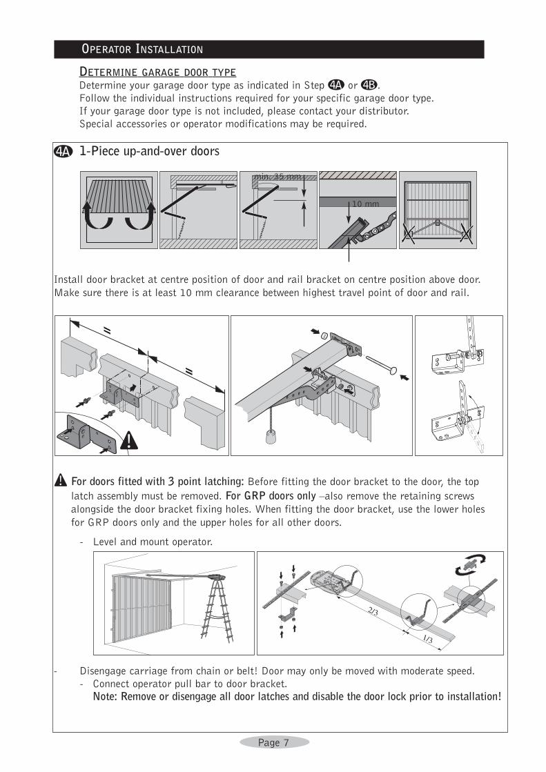
Install door bracket at centre position of door and rail bracket on centre position above door.
Make sure there is at least 10 mm clearance between highest travel point of door and rail.
! For doors fitted with 3 point latching: Before fitting the door bracket to the door, the top
latch assembly must be removed. For GRP doors only –also remove the retaining screws
alongside the door bracket fixing holes. When fitting the door bracket, use the lower holes
for GRP doors only and the upper holes for all other doors.
- Level and mount operator.
- Disengage carriage from chain or belt! Door may only be moved with moderate speed.
- Connect operator pull bar to door bracket.
Note: Remove or disengage all door latches and disable the door lock prior to installation!
DETERMINE GARAGE DOOR TYPEDetermine your garage door type as indicated in Step � or ©.
Follow the individual instructions required for your specific garage door type.
If your garage door type is not included, please contact your distributor.
Special accessories or operator modifications may be required.
OPERATOR INSTALLATION
1-Piece up-and-over doors
min. 35 mm
10 mm
Page 8
©
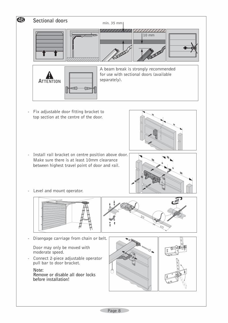
- Fix adjustable door fitting bracket to
top section at the centre of the door.
- Install rail bracket on centre position above door.
Make sure there is at least 10mm clearance
between highest travel point of door and rail.
- Level and mount operator.
- Disengage carriage from chain or belt.
Door may only be moved withmoderate speed.
- Connect 2-piece adjustable operatorpull bar to door bracket.
Note: Remove or disable all door locksbefore installation!
A beam break is strongly recommended
for use with sectional doors (available
separately).!
ATTENTION
Sectional doorsmin. 35 mm
10 mm
Page 9
FOR ALL OTHER DOOR TYPES PLEASE CONTACT YOUR DISTRIBUTOR!
e Make sure motorhousing and rail are mounted correctly and secured. Strengthen where needed.
f Install light bulb. Type E14, max. 40 Watt (not included).
! Attention: before you start Operator programming please make sure your carriage is engaged to chain or belt and door arm is attached to door.
OPERATOR CONTROL PANEL INDICATIONS
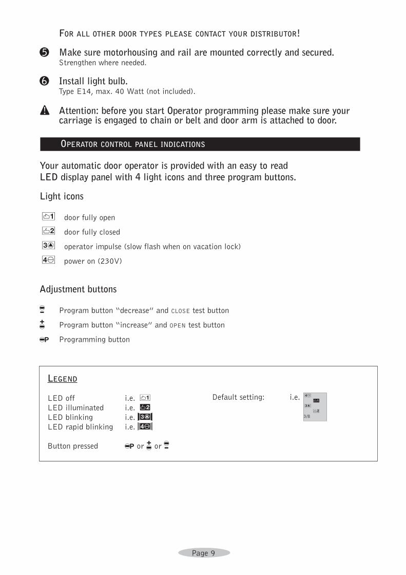
Your automatic door operator is provided with an easy to read LED display panel with 4 light icons and three program buttons.
Light icons
2 door fully open
4 door fully closed
6 operator impulse (slow flash when on vacation lock)
8 power on (230V)
Adjustment buttons
/ Program button “decrease” and CLOSE test button
& Program button “increase” and OPEN test button
% Programming button
LEGEND
LED off i.e. 2LED illuminated i.e. RLED blinking i.e. HLED rapid blinking i.e. ,
Button pressed % or & or /
Default setting: i.e. 8Q7W6E543/8
Page 10
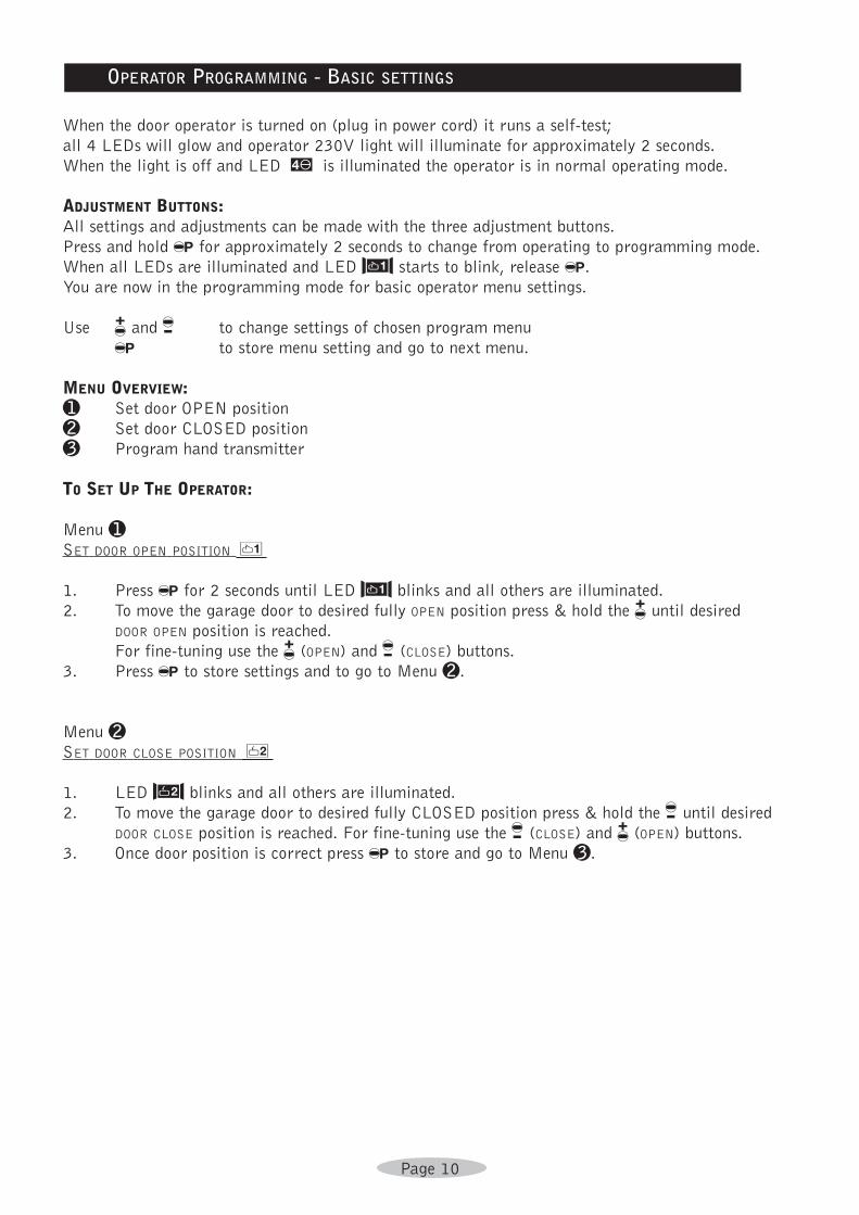
OPERATOR PROGRAMMING - BASIC SETTINGS
When the door operator is turned on (plug in power cord) it runs a self-test;
all 4 LEDs will glow and operator 230V light will illuminate for approximately 2 seconds.
When the light is off and LED I is illuminated the operator is in normal operating mode.
ADJUSTMENT BUTTONS:All settings and adjustments can be made with the three adjustment buttons.
Press and hold % for approximately 2 seconds to change from operating to programming mode.
When all LEDs are illuminated and LED S starts to blink, release %.
You are now in the programming mode for basic operator menu settings.
Use & and / to change settings of chosen program menu
% to store menu setting and go to next menu.
MENU OVERVIEW:a Set door OPEN position
b Set door CLOSED position
c Program hand transmitter
TO SET UP THE OPERATOR:
Menu aSET DOOR OPEN POSITION 2
1. Press % for 2 seconds until LED S blinks and all others are illuminated.
2. To move the garage door to desired fully OPEN position press & hold the & until desired
DOOR OPEN position is reached.
For fine-tuning use the & (OPEN) and / (CLOSE) buttons.
3. Press % to store settings and to go to Menu b.
Menu bSET DOOR CLOSE POSITION 4
1. LED F blinks and all others are illuminated.
2. To move the garage door to desired fully CLOSED position press & hold the / until desired
DOOR CLOSE position is reached. For fine-tuning use the / (CLOSE) and & (OPEN) buttons.
3. Once door position is correct press % to store and go to Menu c.
Page 11
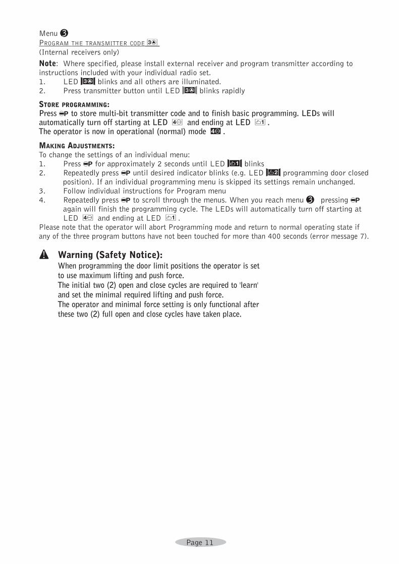
Menu cPROGRAM THE TRANSMITTER CODE6(Internal receivers only)
Note: Where specified, please install external receiver and program transmitter according toinstructions included with your individual radio set.1. LED H blinks and all others are illuminated.2. Press transmitter button until LED N blinks rapidly
STORE PROGRAMMING:Press % to store multi-bit transmitter code and to finish basic programming. LEDs willautomatically turn off starting at LED 8 and ending at LED 2.The operator is now in operational (normal) mode I.
MAKING ADJUSTMENTS:To change the settings of an individual menu:1. Press % for approximately 2 seconds until LED S blinks2. Repeatedly press % until desired indicator blinks (e.g. LED F programming door closed
position). If an individual programming menu is skipped its settings remain unchanged.3. Follow individual instructions for Program menu4. Repeatedly press % to scroll through the menus. When you reach menu c pressing %
again will finish the programming cycle. The LEDs will automatically turn off starting atLED 8 and ending at LED 2.
Please note that the operator will abort Programming mode and return to normal operating state ifany of the three program buttons have not been touched for more than 400 seconds (error message 7).
! Warning (Safety Notice): When programming the door limit positions the operator is setto use maximum lifting and push force. The initial two (2) open and close cycles are required to 'learn'and set the minimal required lifting and push force. The operator and minimal force setting is only functional after these two (2) full open and close cycles have taken place.
Page 12
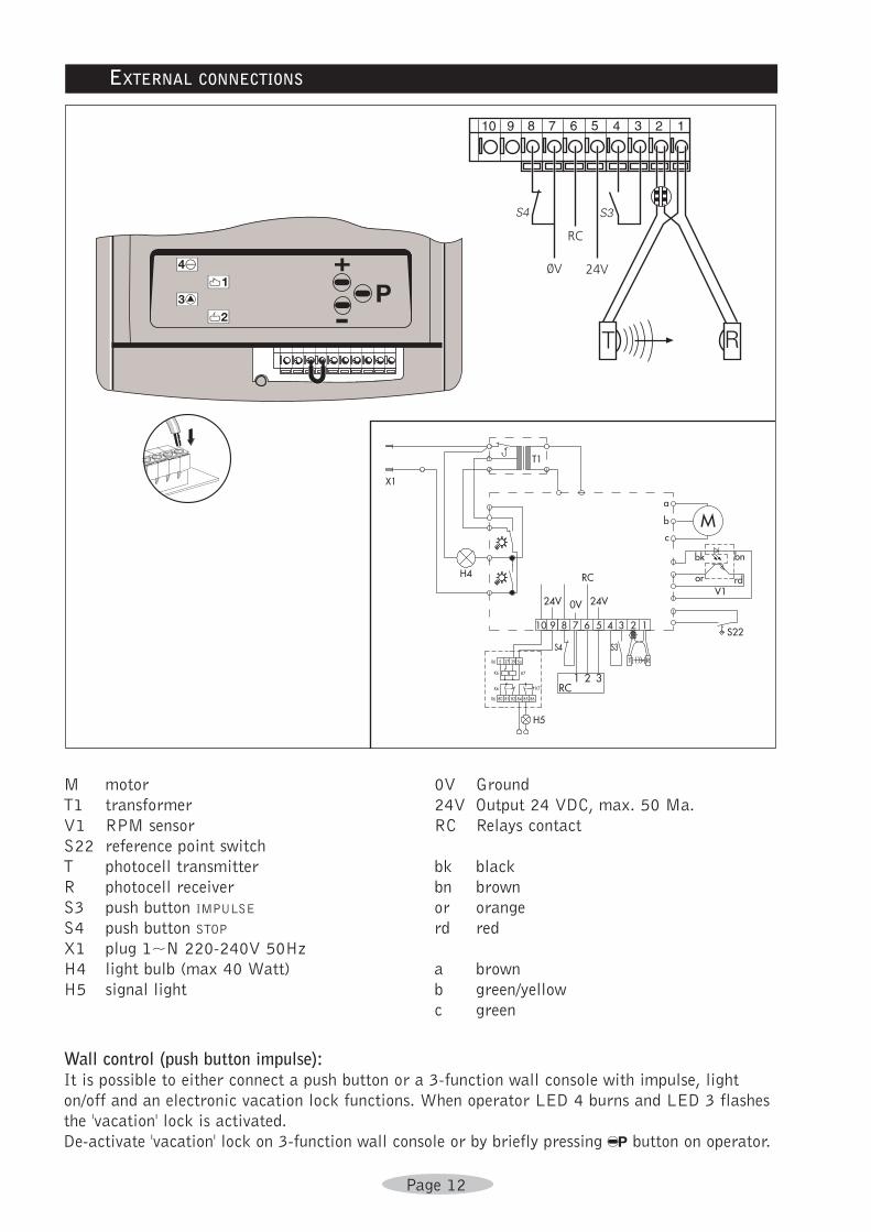
EXTERNAL CONNECTIONS
M motor
T1 transformer
V1 RPM sensor
S22 reference point switch
T photocell transmitter
R photocell receiver
S3 push button IMPULSE
S4 push button STOP
X1 plug 1~N 220-240V 50Hz
H4 light bulb (max 40 Watt)
H5 signal light
0V Ground
24V Output 24 VDC, max. 50 Ma.
RC Relays contact
bk black
bn brown
or orange
rd red
a brown
b green/yellow
c green
Wall control (push button impulse):It is possible to either connect a push button or a 3-function wall console with impulse, light
on/off and an electronic vacation lock functions. When operator LED 4 burns and LED 3 flashes
the 'vacation' lock is activated.
De-activate 'vacation' lock on 3-function wall console or by briefly pressing % button on operator.
Page 13
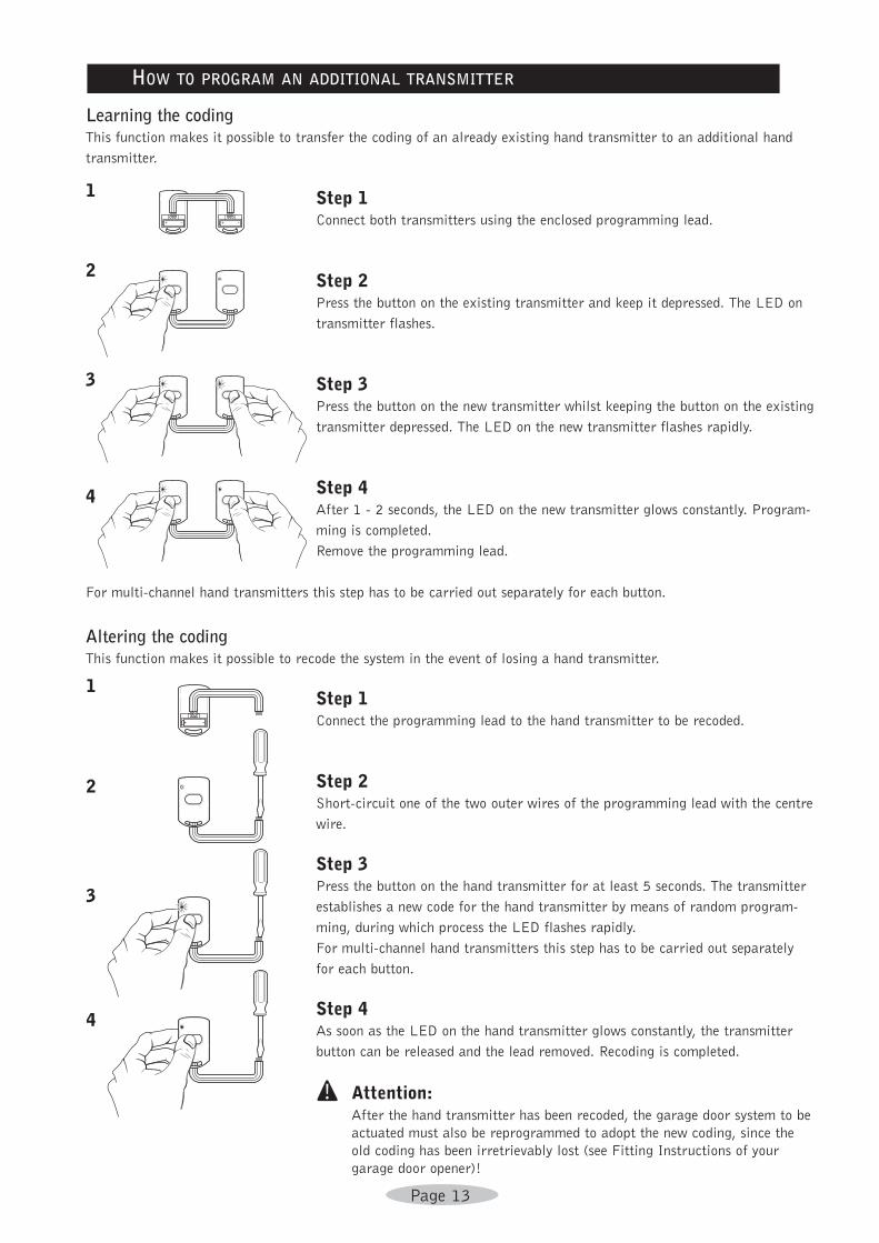
Learning the codingThis function makes it possible to transfer the coding of an already existing hand transmitter to an additional hand
transmitter.
Step 1 Connect both transmitters using the enclosed programming lead.
Step 2 Press the button on the existing transmitter and keep it depressed. The LED on
transmitter flashes.
Step 3 Press the button on the new transmitter whilst keeping the button on the existing
transmitter depressed. The LED on the new transmitter flashes rapidly.
Step 4After 1 - 2 seconds, the LED on the new transmitter glows constantly. Program-
ming is completed.
Remove the programming lead.
For multi-channel hand transmitters this step has to be carried out separately for each button.
Altering the codingThis function makes it possible to recode the system in the event of losing a hand transmitter.
Step 1 Connect the programming lead to the hand transmitter to be recoded.
Step 2 Short-circuit one of the two outer wires of the programming lead with the centre
wire.
Step 3 Press the button on the hand transmitter for at least 5 seconds. The transmitter
establishes a new code for the hand transmitter by means of random program-
ming, during which process the LED flashes rapidly.
For multi-channel hand transmitters this step has to be carried out separately
for each button.
Step 4 As soon as the LED on the hand transmitter glows constantly, the transmitter
button can be released and the lead removed. Recoding is completed.
! Attention: After the hand transmitter has been recoded, the garage door system to be
actuated must also be reprogrammed to adopt the new coding, since the
old coding has been irretrievably lost (see Fitting Instructions of your
garage door opener)!
HOW TO PROGRAM AN ADDITIONAL TRANSMITTER
1
2
3
4
1
2
3
4
Page 14
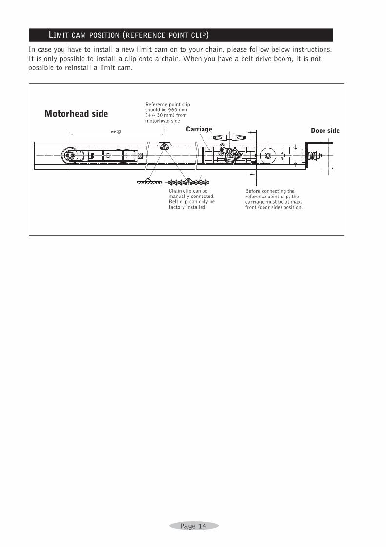
In case you have to install a new limit cam on to your chain, please follow below instructions.
It is only possible to install a clip onto a chain. When you have a belt drive boom, it is not
possible to reinstall a limit cam.
Motorhead sideReference point clipshould be 960 mm(+/- 30 mm) frommotorhead side
Carriage Door side
Chain clip can bemanually connected.Belt clip can only befactory installed
Before connecting thereference point clip, thecarriage must be at max.front (door side) position.
LIMIT CAM POSITION (REFERENCE POINT CLIP)
Page 15
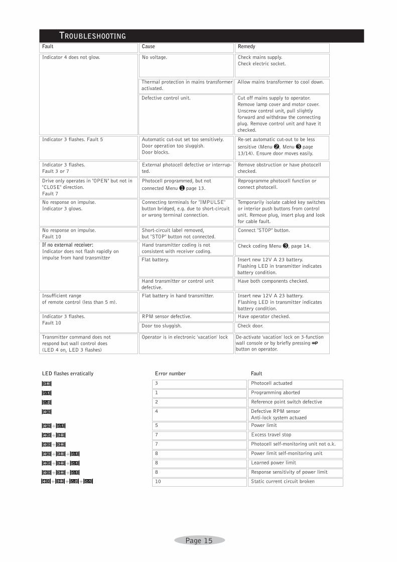
Static current circuit broken10K+H+F+S
Response sensitivity of power limit8K+H+S
Learned power limit8K+H+S
Power limit self-monitoring unit8K+H+S
Photocell self-monitoring unit not o.k.7K+H
Excess travel stop7K+H
Power limit5K+S
Defective RPM sensor
Anti-lock system actuaed
4K
Reference point switch defective2F
Programming aborted1S
Photocell actuated3H
FaultError numberLED flashes erratically
De-activate 'vacation' lock on 3-functionwall console or by briefly pressing %button on operator.
Operator is in electronic 'vacation' lockTransmitter command does not
respond but wall control does
(LED 4 on, LED 3 flashes)
Check door.Door too sluggish.
Have operator checked.RPM sensor defective.Indicator 3 flashes.
Fault 10
Insert new 12V A 23 battery.
Flashing LED in transmitter indicates
battery condition.
Flat battery in hand transmitter.Insufficient range
of remote control (less than 5 m).
Have both components checked.Hand transmitter or control unit
defective.
Insert new 12V A 23 battery.
Flashing LED in transmitter indicates
battery condition.
Flat battery.
Check coding Menu c, page 14.Hand transmitter coding is not
consistent with receiver coding.
If no external receiver:Indicator does not flash rapidly on
impulse from hand transmitter
Connect "STOP" button.Short-circuit label removed,
but "STOP" button not connected.
No response on impulse.
Fault 10
Temporarily isolate cabled key switches
or interior push buttons from control
unit. Remove plug, insert plug and look
for cable fault.
Connecting terminals for "IMPULSE"
button bridged, e.g. due to short-circuit
or wrong terminal connection.
No response on impulse.
Indicator 3 glows.
Reprogramme photocell function or
connect photocell.
Photocell programmed, but not
connected Menu a page 13.
Drive only operates in "OPEN" but not in
"CLOSE" direction.
Fault 7
Remove obstruction or have photocell
checked.
External photocell defective or interrup-
ted.
Indicator 3 flashes.
Fault 3 or 7
Re-set automatic cut-out to be less
sensitive (Menu b, Menu c page
13/14). Ensure door moves easily.
Automatic cut-out set too sensitively.
Door operation too sluggish.
Door blocks.
Indicator 3 flashes. Fault 5
Cut off mains supply to operator.
Remove lamp cover and motor cover.
Unscrew control unit, pull slightly
forward and withdraw the connecting
plug. Remove control unit and have it
checked.
Defective control unit.
Allow mains transformer to cool down.Thermal protection in mains transformer
activated.
Check mains supply.
Check electric socket.
No voltage.Indicator 4 does not glow.
RemedyCauseFault
TROUBLESHOOTING
Page 16
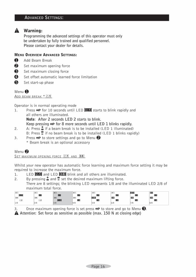
! Warning: Programming the advanced settings of this operator must onlybe undertaken by fully trained and qualified personnel. Please contact your dealer for details.
MENU OVERVIEW ADVANCED SETTINGS:a Add Beam Break
b Set maximum opening force
c Set maximum closing force
d Set offset automatic learned force limitation
e Set start-up phase
Menu aADD BEAM BREAK *2
Operator is in normal operating mode
1. Press % for 10 seconds until LED S starts to blink rapidly and
all others are illuminated.
Note: After 2 seconds LED 2 starts to blink. Keep pressing % for 8 more seconds until LED 1 blinks rapidly.
2. A: Press & if a beam break is to be installed (LED 1 illuminated)
B: Press / if no beam break is to be installed (LED 1 blinks rapidly)
3. Press % to store settings and go to Menu b* Beam break is an optional accessory
Menu bSET MAXIMUM OPENING FORCE 2 AND 6
Whilst your new operator has automatic force learning and maximum force setting it may berequired to increase the maximum force.
1. LED S and LED H blink and all others are illuminated.
2. By pressing & and / set the desired maximum lifting force.
There are 8 settings; the blinking LED represents 1/8 and the illuminated LED 2/8 of
maximum total force.
3. Once maximum opening force is set press % to store and go to Menu c.! Attention: Set force as sensitive as possible (max. 150 N at closing edge)
IQUWZETR8/8
KQUWZETR7/8
8Q7WZETR6/8
8Q7WHETR5/8
8Q7W6E5R4/8
8Q7W6E5F3/8
8Q7W63542/8
8Q7S63541/8
ADVANCED SETTINGS:
Page 17
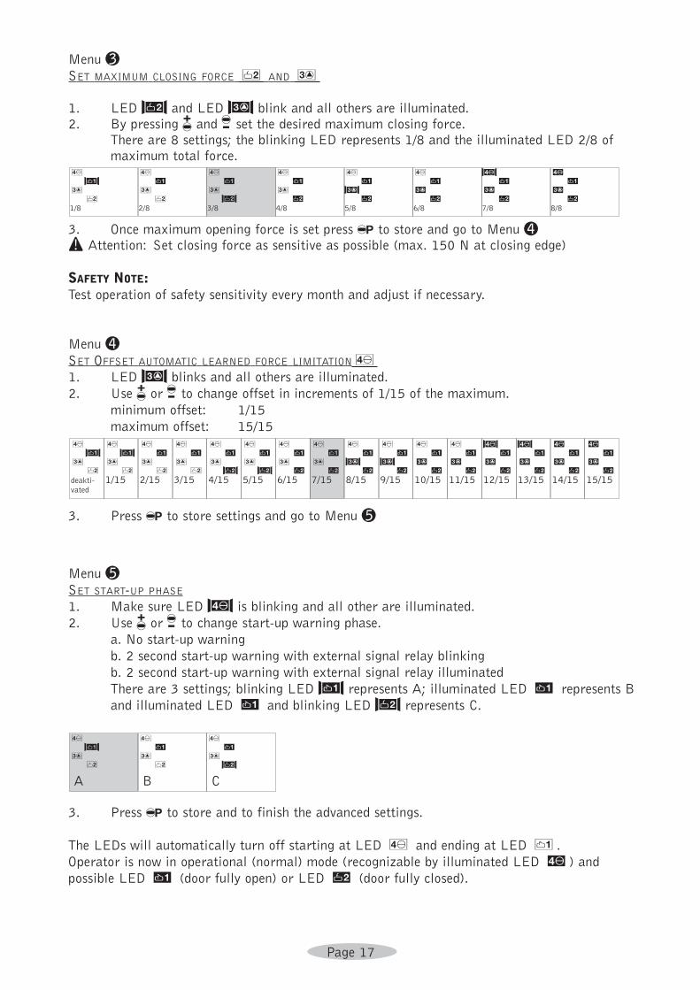
Menu cSET MAXIMUM CLOSING FORCE 4 AND 6
1. LED F and LED H blink and all others are illuminated.2. By pressing & and / set the desired maximum closing force.
There are 8 settings; the blinking LED represents 1/8 and the illuminated LED 2/8 ofmaximum total force.
3. Once maximum opening force is set press % to store and go to Menu d! Attention: Set closing force as sensitive as possible (max. 150 N at closing edge)
SAFETY NOTE:Test operation of safety sensitivity every month and adjust if necessary.
Menu dSET OFFSET AUTOMATIC LEARNED FORCE LIMITATION81. LED H blinks and all others are illuminated.
2. Use & or / to change offset in increments of 1/15 of the maximum.
minimum offset: 1/15
maximum offset: 15/15
3. Press % to store settings and go to Menu e
Menu eSET START-UP PHASE
1. Make sure LED K is blinking and all other are illuminated.
2. Use & or / to change start-up warning phase.
a. No start-up warning
b. 2 second start-up warning with external signal relay blinking
b. 2 second start-up warning with external signal relay illuminated
There are 3 settings; blinking LED S represents A; illuminated LED W represents B
and illuminated LED W and blinking LED F represents C.
3. Press % to store and to finish the advanced settings.
The LEDs will automatically turn off starting at LED 8 and ending at LED 2.
Operator is now in operational (normal) mode (recognizable by illuminated LED I) and
possible LED W (door fully open) or LED R (door fully closed).
8Q7W6E5F
C
8Q7W6354
B
8Q7S6354
A
IQUWZETR15/15
IQUWZETR14/15
KQUWZETR13/15
KQJWZETR12/15
8Q7WZETR11/15
8Q7WZETR10/15
8Q7WHETR9/15
8Q7WHEGR8/15
8Q7W6E5R7/15
8Q7W6E5R6/15
8Q7W6E5F5/15
8Q7W6D5F4/15
8Q7W63543/15
8Q7W63542/15
8Q7S63541/15
8A7S6354deakti-vated
IQUWZETR8/8
KQUWZETR7/8
8Q7WZETR6/8
8Q7WHETR5/8
8Q7W6E5R4/8
8Q7W6E5F3/8
8Q7W63542/8
8Q7S63541/8
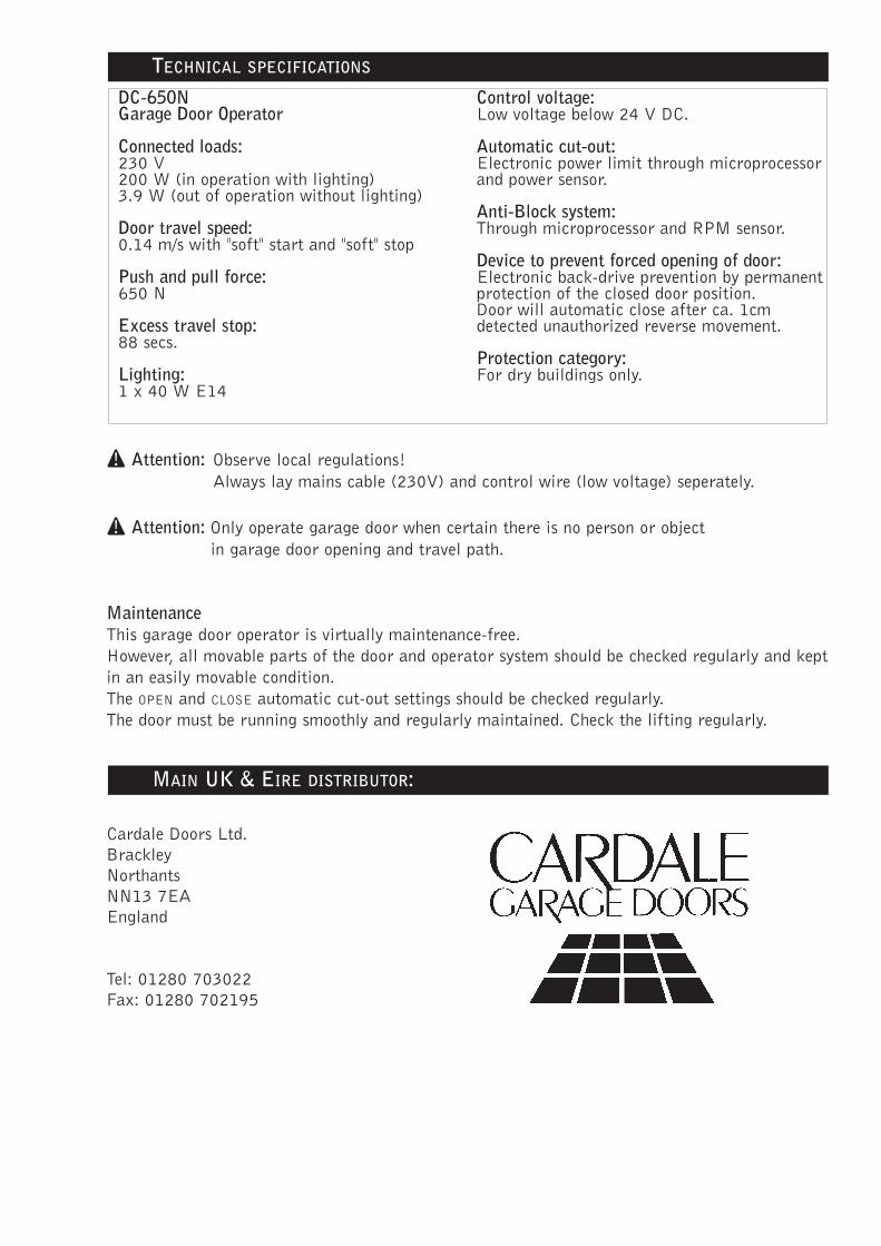
! Attention: Observe local regulations!
Always lay mains cable (230V) and control wire (low voltage) seperately.
! Attention: Only operate garage door when certain there is no person or object
in garage door opening and travel path.
MaintenanceThis garage door operator is virtually maintenance-free.
However, all movable parts of the door and operator system should be checked regularly and kept
in an easily movable condition.
The OPEN and CLOSE automatic cut-out settings should be checked regularly.
The door must be running smoothly and regularly maintained. Check the lifting regularly.
Cardale Doors Ltd.
Brackley
Northants
NN13 7EA
England
Tel: 01280 703022
Fax: 01280 702195
MAIN UK & EIRE DISTRIBUTOR:
DC-650NGarage Door Operator
Connected loads:230 V200 W (in operation with lighting)3.9 W (out of operation without lighting)
Door travel speed:0.14 m/s with "soft" start and "soft" stop
Push and pull force:650 N
Excess travel stop:88 secs.
Lighting:1 x 40 W E14
Control voltage:Low voltage below 24 V DC.
Automatic cut-out:Electronic power limit through microprocessorand power sensor.
Anti-Block system:Through microprocessor and RPM sensor.
Device to prevent forced opening of door:Electronic back-drive prevention by permanentprotection of the closed door position. Door will automatic close after ca. 1cmdetected unauthorized reverse movement.
Protection category: For dry buildings only.
TECHNICAL SPECIFICATIONS
✄
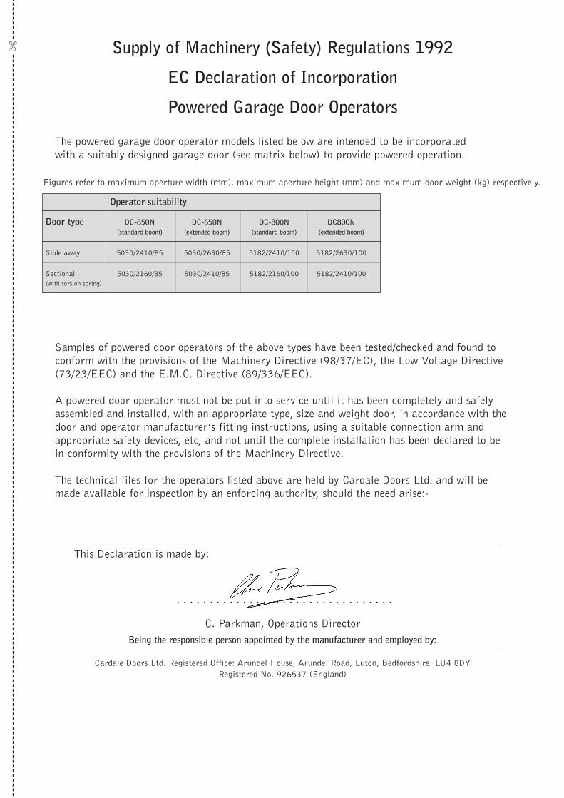
Supply of Machinery (Safety) Regulations 1992
EC Declaration of Incorporation
Powered Garage Door Operators
The powered garage door operator models listed below are intended to be incorporated
with a suitably designed garage door (see matrix below) to provide powered operation.
Samples of powered door operators of the above types have been tested/checked and found to
conform with the provisions of the Machinery Directive (98/37/EC), the Low Voltage Directive
(73/23/EEC) and the E.M.C. Directive (89/336/EEC).
A powered door operator must not be put into service until it has been completely and safely
assembled and installed, with an appropriate type, size and weight door, in accordance with the
door and operator manufacturer’s fitting instructions, using a suitable connection arm and
appropriate safety devices, etc; and not until the complete installation has been declared to be
in conformity with the provisions of the Machinery Directive.
The technical files for the operators listed above are held by Cardale Doors Ltd. and will be
made available for inspection by an enforcing authority, should the need arise:-
Being the responsible person appointed by the manufacturer and employed by:
Cardale Doors Ltd. Registered Office: Arundel House, Arundel Road, Luton, Bedfordshire. LU4 8DY
Registered No. 926537 (England)
This Declaration is made by:
. . . . . . . . . . . . . . . . . . . . . . . . . . . . . . . . .
C. Parkman, Operations Director
Figures refer to maximum aperture width (mm), maximum aperture height (mm) and maximum door weight (kg) respectively.
Operator suitability
Door type DC-650N DC-650N DC-800N DC800N(standard boom) (extended boom) (standard boom) (extended boom)
Slide away 5030/2410/85 5030/2630/85 5182/2410/100 5182/2630/100
Sectional 5030/2160/85 5030/2410/85 5182/2160/100 5182/2410/100
(with torsion spring)

ISSUE B January 99
DECLARATION OF INCORPORATION
This Declaration of Incorporation has been prepared by the powered garage door
operator manufacturer to meet the requirements of the Supply of Machinery
(Safety) Regulations {Machinery Directive} and signifies that the accompanying
powered garage door operator, if installed in accordance with the manufacturer’s
detailed instructions, will be suitable to be incorporated with a suitably designed
garage door with a compatible Declaration of Incorporation.
It is the responsibility of the installing company to ensure that doors and drive units
are correctly matched prior to installation.
It is also the responsibility of the installing company, as the Responsible Person, to
ensure that a suitably nominated person should confirm that the power operated
door has been installed in accordance with the instructions provided by both the
door and drive unit manufacturer.
It is also the responsibility of the installing company to check after installation the
operation of the power operated door and that any safety devices provided are sui-
table for the application and are all working satisfactorily. This will permit the
nominated person to attach a CE label identifying the name of the installing com-
pany, a unique door reference number and a date of completion, and to complete
and issue a Declaration of Conformity (see note below).
One copy of the Declaration of Conformity is to be issued to the client and one copy
is to be retained by the installing company, together with the relevant two Declara-
tions of Incorporation. In accordance with the requirements of the Machinery
Directive and the UK supply of Machinery (Safety) Regulations, these records are
to be retained on file for a period of ten years.
NOTE
Duplicate printed pads set out in the format of Declarations of Conformity in order
to allow on site completion are available at a reasonable cost from the DSMA for
both members and non-members. Alternatively, for an additional cost, a technical
records file with full details of requirements and procedures for compliance, and
including the necessary filing divisions, is also available.
The Door & Shutter Manufacturers’ Association, 42 Heath Street,
Tamworth, Staffordshire B79 7JH Telephone: 01827 52337 Fax: 01827 310827
✄