MUL-288 Multímetro digital con detector de voltaje...El indicador se encenderá al detectar voltaje...
76
MUL-288 Multímetro digital con detector de voltaje 0715v Manual de instrucciones V0.1 HOLD 20K 20 20 200 200 600 600 200K 200 200 200n 20n 20m 200m 10 10 200m 20m 2 TEMP A hFE 20kHz 2 2K 2M 20M 200M 200m MS8260C A COM Hz hFE mA TEMP 10A 600V CAT III MAX 10A FUSED MAX 30 sec. every 15 min.
Transcript of MUL-288 Multímetro digital con detector de voltaje...El indicador se encenderá al detectar voltaje...

MUL-288
Multímetro digital con detector de voltaje
0715v Manual de instrucciones V0.1
HOLD
20K
20
20
200
200
600600
200K
200
200
200n
20n
20m
200m10
10200m 20m
2TEMP
AhFE 20kHz
2
2K
2M 20M200M
200m
MS8260C
A
COM
Hz
hFEmATEMP
10A
600V
CAT III
MAX 10A
FUSED
MAX 30 sec.
every 15 min.
2
MULTÍMETRO DIGITAL CON DETECTOR DE VOLTAJE
Gracias por la compra de este producto Steren.
Este manual contiene todas las indicaciones necesarias para manejar su nuevo Multímetro digital con detector de voltaje
Por favor, revíselo completamente para estar seguro de cómo utilizar apropiadamente el producto.
Para apoyo, compras y todo lo nuevo que tiene Steren, visite nuestro sitio web:
www.steren.com
MUL-288
La información que se muestra en este manual sirve únicamente como referencia sobre el producto. Debido a actualizaciones pueden existir diferencias.
Por favor, consulte nuestra página web (www.steren.com) para obtener la versión más reciente del instructivo.
3
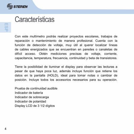
ÍNDICE1- Contenido2- Controles3- Advertencias
4- Precauciones durante el uso4.1 Mantenimiento general5. Símbolos de la pantalla
6- Instrucciones6.1 Colocación de batería y cambio defusibles7- Modo retención de datos8- Medición por inductancia9- Prueba de continuidad audible10- Medición de resistencia Ω11- Medición de voltaje directo V - - -12- Medición de voltaje alterno V ~13- Prueba de diodos14- Medición de frecuencia
15- Medición de corriente directa A - - -
16- Medición de corriente alterna A ~17- Medición de temperatura
18- Medición de capacitancia (rango 20 nF a 200 μF)
19- Medición de trasistores20- Tablas de especifi caciones
.......................................................5
.......................................................6
.......................................................7
.......................................................10
.......................................................11
.......................................................12
.......................................................14
.......................................................14
.....................................................15
.....................................................16
.....................................................17
.....................................................18
.....................................................19
.....................................................20
.....................................................21
.....................................................22
.....................................................23
.....................................................25
.....................................................26
.....................................................28
.....................................................29
.....................................................31
4
Características
Con este multímetro podrás realizar proyectos escolares, trabajos de reparación o mantenimiento de manera profesional. Cuenta con la función de detección de voltaje, muy útil al querer localizar líneasde cables energizados que se encuentran en paredes o canaletas dedifícil acceso. Obtén mediciones precisas de voltaje, corriente, capacitancia, temperatura, frecuencia, continuidad y beta de transistores.
Tiene la posibilidad de iluminar el display para observar las lecturas a pesar de que haya poca luz, además incluye función que retiene los datos en la pantalla (HOLD), ideal para tomar notas o cambiar de posición. Incluye todos los accesorios necesarios para su operación.
Prueba de continuidad audibleIndicador de bateríaIndicador de sobrecargaIndicador de polaridadDisplay LCD de 3 1/2 dígitos
5
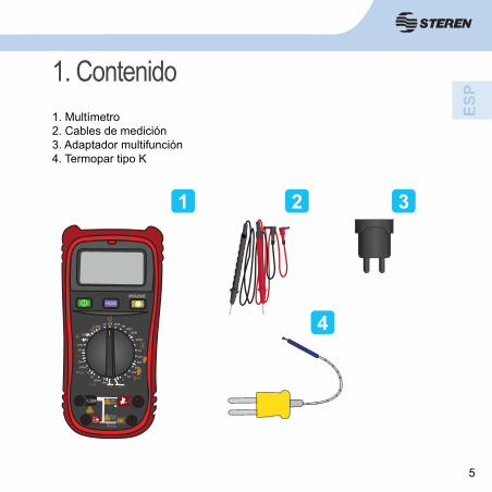
1. Contenido1. Multímetro2. Cables de medición3. Adaptador multifunción4. Termopar tipo K
1 2 3
4HOLD
20K
20
20
200
200
600
600
200K200
200
200n
20n
20m
200m
1010
200m20m
2
TEMP
A hFE 20kHz
2
2K2M
20M200M
200m
MS8260C
A
COM Hz
hFEmATEMP 10A
600VCAT III
MAX 10AFUSED
MAX 30 sec.every 15 min.
6
2-Controles
HOLD
20K
20
20
200
200
750
1000
200K200
200
200n
20n
20m
200m
1010
200m20m
2
TEMP
A hFE 20kHz
2
2K 2M20M
200M
200m
MS8260C
A
COM Hz
hFEmATEMP 10A
600VCAT III
MAX 10AFUSED
MAX 30 sec.every 15 min.
1 2
3
4
5
6
7
8
8
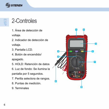
1. Área de detección de voltaje.2. Indicador de detección de voltaje.3. Pantalla LCD. 4. Botón de encendido/apagado.5. HOLD: Retención de datos6. Luz de fondo: Se ilumina la pantalla por 5 segundos.7. Perilla selectora de rangos.8. Puntas de medición.9. Terminales 9
600600
7
3. AdvertenciasPara evitar el riesgo de un choque eléctrico o daño en su persona y un posible daño al medidor o al equipo bajo prueba, observar las siguientes reglas:
- Quite los cables de prueba al abrir o quitar la tapa del comparti-mento de baterías del multímetro.
- Antes de abrir el instrumento, desconecte todas las fuentes de la corriente eléctrica y asegúrese de no estar cargado con estática eléctrica, ya que puede destruir componentes internos.
- Cualquier mantenimiento o trabajo de reparación llevado a cabo con el multímetro debe ser llevado a cabo por personal califi cado, después de haber tomado en cuenta las instrucciones de este manual.
8
3. Advertencias- Antes de utilizar el medidor inspeccione la cubierta. No lo use si la cubierta o parte de ésta ha sido removida. Revise la pérdida de plástico sobre todo alrededor de los conectores.
- Inspeccione las puntas de prueba por daño en el aislamiento o exposición de las partes metálicas. Revise las puntas de prueba por continuidad. Reemplace las puntas dañadas con un modelo idéntico de las mismas características eléctricas antes de utilizar el medidor.
- No aplicar más de la razón de voltaje que se marca en el medidor, entre las terminales o entre cualquier terminal y tierra.
- El interruptor giratorio debe estar colocado en posición recta y nin-gún rango de sobrecarga deberá mostrarse durante la medición, esto evita el daño del medidor.
- Utilice las terminales, funciones y rango adecuados para sus mediciones.

9
3. Advertencias- No use o almacene el medidor en un ambiente de alta temperatura, humedad, explosivo, infl amable o con campo magnético fuerte. El desempeño del medidor puede deteriorarse después de ser humedecido o mojado.
-Cuando use las puntas de prueba mantenga los dedos más allá de las guardas.
- Desconecte la energía del circuito y descargue los capacitores de alto voltaje antes de medir resistencia, continuidad, diodos, corriente o capacitancia.
- Antes de medir corriente revise los fusibles del medidor y apague el circuito antes de conectar el medidor al circuito.
- Con la batería baja el medidor puede producir falsas lecturas que pueden conducir a un choque eléctrico y una lesión personal.
- El circuito interno no deberá ser alterado a riesgo de sufrir un daño o accidente.- Si no va a usar el medidor por un largo tiempo, retire la batería..
10
4. Precauciones durante el uso- Es posible que la pantalla se vuelva inestable o marque errores si se usa el multímetro cerca de equipo que genere ruido.- Sólo use el multímetro de acuerdo con este instructivo.- Tenga extrema precaución cuando trabaje con conductores desnudos o barras colectoras.- No opere el multímetro cerca de gas explosivo, vapor o polvo.- Verifi que la operación del multímetro midiendo un voltaje ya conocido. - Use las terminales, funciones y rangos adecuados para sus mediciones.- Cuando no sepa el rango de medición, comience por el más alto.- No exceda los límites máximos de los valores de entrada mostrados en las tablas.- No toque las terminales que no están en uso cuando esté midiendo circuitos.- Cuando haga las conexiones, primero conecte el cable de prueba común y después el cable de prueba vivo y viceversa, cuando desconecte, hágalo primero con el cable de prueba vivo y después el común.- Antes de cambiar de función, desconecte los cables de prueba del circuito a medir.
11
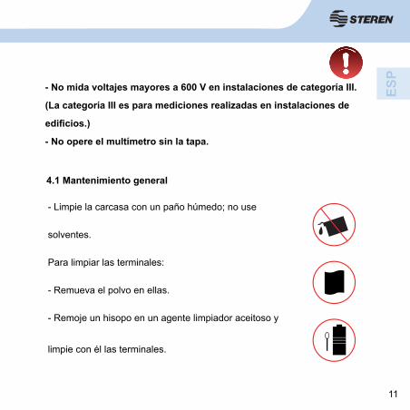
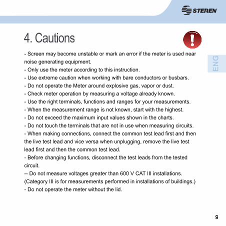
- No mida voltajes mayores a 600 V en instalaciones de categoría III.
(La categoría III es para mediciones realizadas en instalaciones de
edifi cios.)
- No opere el multímetro sin la tapa.
4.1 Mantenimiento general
- Limpie la carcasa con un paño húmedo; no use
solventes.
Para limpiar las terminales:
- Remueva el polvo en ellas.
- Remoje un hisopo en un agente limpiador aceitoso y
limpie con él las terminales.
12
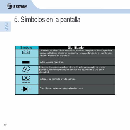
5. Símbolos en la pantalla
Símbolo SignificadoLa batería está baja. Para evitar lecturas falsas, que podrían llevar a posibles choques eléctricos o lesiones corporales, remplace la batería en cuanto este símbolo aparezca en la pantalla.
Indica lecturas negativas.
AC Indicador de corriente o voltaje alterno. El valor desplegado es el valor promedio, calibrado para indicar el valor rms equivalente a una onda sinusoidal.
DC Indicador de corriente o voltaje directo.
El multímetro está en modo prueba de diodos
13
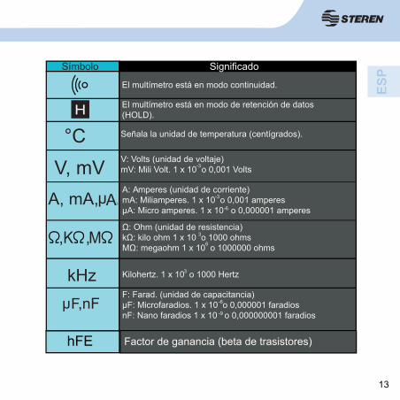
Símbolo Significado
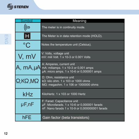
El multímetro está en modo continuidad.
El multímetro está en modo de retención de datos (HOLD).
Señala la unidad de temperatura (centígrados).
V: Volts (unidad de voltaje)mV: Mili Volt. 1 x 10 o 0,001 Volts
A: Amperes (unidad de corriente)mA: Miliamperes. 1 x 10 o 0,001 amperesµA: Micro amperes. 1 x 10 o 0,000001 amperes
H
°CV, mV
A, mA, Ah
,K ,M
kHz Kilohertz. 1 x 10 o 1000 Hertz
hF,nFF: Farad. (unidad de capacitancia)µF: Microfaradios. 1 x 10 o 0,000001 faradiosnF: Nano faradios 1 x 10 o 0,000000001 faradios
3
3
6
-6
-9
-6
-3
-3
hFE Factor de ganancia (beta de trasistores)
Ah
14
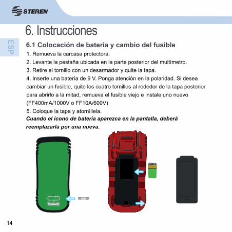
6.1 Colocación de batería y cambio del fusible1. Remueva la carcasa protectora.2. Levante la pestaña ubicada en la parte posterior del multímetro.3. Retire el tornillo con un desarmador y quite la tapa.4. Inserte una batería de 9 V. Ponga atención en la polaridad. Si desea cambiar un fusible, quite los cuatro tornillos al rededor de la tapa posterior para abrirlo a la mitad, remueva el fusible viejo e instale uno nuevo (FF400mA/1000V o FF10A/600V)5. Coloque la tapa y atorníllela.Cuando el ícono de batería aparezca en la pantalla, deberá reemplazarla por una nueva.
6. Instrucciones
15
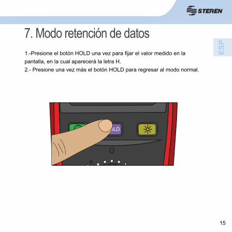
7. Modo retención de datos1.-Presione el botón HOLD una vez para fi jar el valor medido en la pantalla, en la cual aparecerá la letra H.2.- Presione una vez más el botón HOLD para regresar al modo normal.
HOLD
16
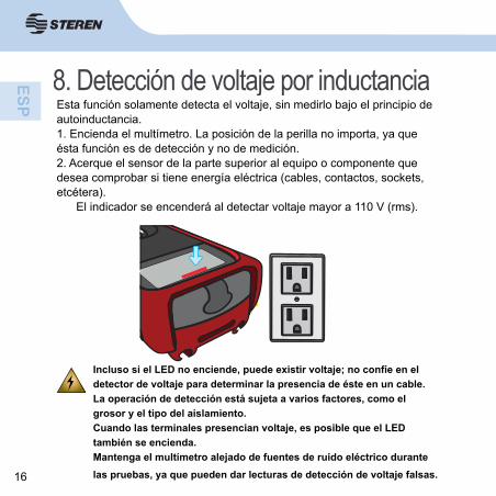
8. Detección de voltaje por inductanciaEsta función solamente detecta el voltaje, sin medirlo bajo el principio de autoinductancia.1. Encienda el multímetro. La posición de la perilla no importa, ya que ésta función es de detección y no de medición.2. Acerque el sensor de la parte superior al equipo o componente que desea comprobar si tiene energía eléctrica (cables, contactos, sockets, etcétera). El indicador se encenderá al detectar voltaje mayor a 110 V (rms).
Incluso si el LED no enciende, puede existir voltaje; no confíe en el detector de voltaje para determinar la presencia de éste en un cable.La operación de detección está sujeta a varios factores, como el grosor y el tipo del aislamiento.Cuando las terminales presencian voltaje, es posible que el LED también se encienda.Mantenga el multímetro alejado de fuentes de ruido eléctrico durante las pruebas, ya que pueden dar lecturas de detección de voltaje falsas.
17
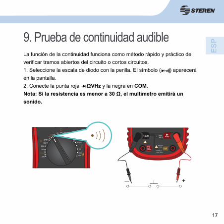
9. Prueba de continuidad audibleLa función de la continuidad funciona como método rápido y práctico de verifi car tramos abiertos del circuito o cortos circuitos.1. Seleccione la escala de diodo con la perilla. El símbolo ( ) aparecerá en la pantalla.2. Conecte la punta roja ΩVHz y la negra en COM.Nota: Si la resistencia es menor a 30 Ω, el multímetro emitirá un sonido.
20K
20
200
200K200
200
200n
20n
20m
TEMP
2
2K 2M20M
200M
200m
+
COM
hFEmATEMP 10A
600VCAT III
MAX 10AFUSED
MAX 30 sec.every 15 min.
Hz
600
18
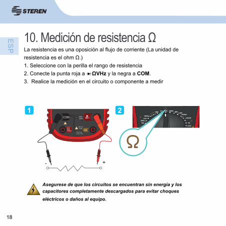
10. Medición de resistencia ΩLa resistencia es una oposición al fl ujo de corriente (La unidad de resistencia es el ohm Ω.) 1. Seleccione con la perilla el rango de resistencia2. Conecte la punta roja a ΩVHz y la negra a COM.3. Realice la medición en el circuito o componente a medir
1 2
+-
COM
hFEmATEMP 10A
600VCAT III
MAX 10AFUSED
MAX 30 sec.every 15 min.
Hz
Asegurese de que los circuitos se encuentran sin energía y los capacitores completamente descargados para evitar choques eléctricos o daños al equipo.
19
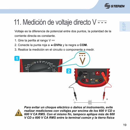
11. Medición de voltaje directo V - - -
Para evitar un choque eléctrico o daños al instrumento, evite realizar mediciones con voltajes por encima de los 600 V CD o 600 V CA RMS. Con el mismo fi n, tampoco aplique más de 600 V CD o 600 V CA RMS entre la terminal común y la tierra física
Voltaje es la diferencia de potencial entre dos puntos, la polaridad de la corriente directa es constante.1. Gire la perilla al rango V --- 2. Conecte la punta roja a ΩVHz y la negra a COM.3. Realice la medición en el circuito o componente a medir.
1
2
+-
COM
hFEmATEMP 10A
600VCAT III
MAX 10AFUSED
MAX 30 sec.every 15 min.
Hz
20
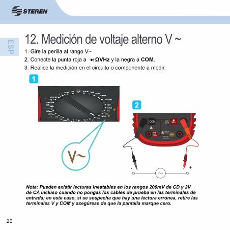
12. Medición de voltaje alterno V ~1. Gire la perilla al rango V~2. Conecte la punta roja a ΩVHz y la negra a COM.3. Realice la medición en el circuito o componente a medir.
1
2
Nota: Pueden existir lecturas inestables en los rangos 200mV de CD y 2V de CA incluso cuando no pongas los cables de prueba en las terminales de entrada; en este caso, si se sospecha que hay una lectura errónea, retire las terminales V y COM y asegúrese de que la pantalla marque cero.
+-
COM
hFEmATEMP 10A
600VCAT III
MAX 10AFUSED
MAX 30 sec.every 15 min.
Hz
600
600
21
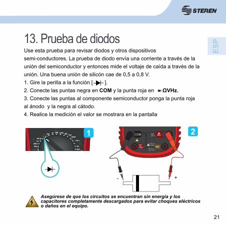
13. Prueba de diodosUse esta prueba para revisar diodos y otros dispositivos semi-conductores. La prueba de diodo envía una corriente a través de la unión del semiconductor y entonces mide el voltaje de caída a través de la unión. Una buena unión de silicón cae de 0,5 a 0,8 V.1. Gire la perilla a la función [ ].2. Conecte las puntas negra en COM y la punta roja en ΩVHz.3. Conecte las puntas al componente semiconductor ponga la punta roja al ánodo y la negra al cátodo.4. Realice la medición el valor se mostrara en la pantalla
1 2
Asegúrese de que los circuitos se encuentran sin energía y los capacitores completamente descargados para evitar choques eléctricos o daños en el equipo.
+-
COM
hFEmATEMP 10A
600VCAT III
MAX 10AFUSED
MAX 30 sec.every 15 min.
Hz
22
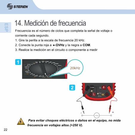
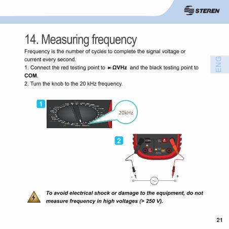
14. Medición de frecuenciaFrecuencia es el número de ciclos que completa la señal de voltaje o corriente cada segundo.1. Gire la perilla a la escala de frecuencia 20 kHz.2. Conecte la punta roja a ΩVHz y la negra a COM.3. Realice la medición en el circuito o componente a medir
Para evitar choques eléctricos o daños en el equipo, no mida frecuencia en voltajes altos (>250 V).
1
2
+-
COM
hFEmATEMP 10A
600VCAT III
MAX 10AFUSED
MAX 30 sec.every 15 min.
Hz
20kHz
23
15. Medición de corriente directa A - - -Para evitar daños en el multímetro o lesiones si el fusible
se quema, nunca intente una medición en un circuito con
corriente donde el potencial del circuito abierto a la tierra
sea mayor a 250 V, y revise el fusible antes de realizar la
medición.
Use las terminales, las funciones y los rangos correctos
para la medición. Nunca coloque los cables de prueba en
paralelo con un circuito o componente cuando los cables
estén conectados a las terminales de corriente.
Corriente es el fl ujo de electrones a través de un conductor.
24
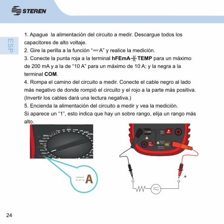
1. Apague la alimentación del circuito a medir. Descargue todos los capacitores de alto voltaje.2. Gire la perilla a la función “--- A” y realice la medición.3. Conecte la punta roja a la terminal hFEmA TEMP para un máximo de 200 mA y a la de “10 A” para un máximo de 10 A; y la negra a la terminal COM.4. Rompa el camino del circuito a medir. Conecte el cable negro al lado más negativo de donde rompió el circuito y el rojo a la parte más positiva. (Invertir los cables dará una lectura negativa.)5. Encienda la alimentación del circuito a medir y vea la medición.Si aparece un “1”, esto indica que hay un sobre rango, elija un rango más alto.
+
COM
hFEmATEMP 10A
600VCAT III
MAX 10AFUSED
MAX 30 sec.every 15 min.
Hz
A
25
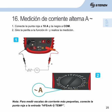
16. Medición de corriente alterna A ~1. Conecte la punta roja a 10 A y la negra a COM.2. Gire la perilla a la función A~ y realice la medición.
Nota: Para medir escalas de corriente más pequeñas, conecte la punta roja a la entrada “hFEmA TEMP”.
+
COM
hFEmATEMP 10A
600VCAT III
MAX 10AFUSED
MAX 30 sec.every 15 min.
Hz1
2
A600
600
26
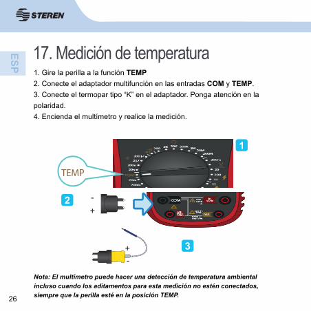
17. Medición de temperatura1. Gire la perilla a la función TEMP2. Conecte el adaptador multifunción en las entradas COM y TEMP.3. Conecte el termopar tipo “K” en el adaptador. Ponga atención en la polaridad.4. Encienda el multímetro y realice la medición.
1
2
3
TEMP
Nota: El multímetro puede hacer una detección de temperatura ambiental incluso cuando los aditamentos para esta medición no estén conectados, siempre que la perilla esté en la posición TEMP.
+-
+-
600
600
27
Para evitar choque eléctrico o daños al instrumento, nunca
aplique más de 250 V CD o 250 V CA RMS entre la terminal °C
y la terminal COM.
Evite usar el multímetro cuando los voltajes excedan 60 V CD
o 24 V CA RMS.
Para evitar daños o quemaduras, no haga mediciones de
temperatura en hornos de microondas.
Nota: Únicamente realiza mediciones en grados °C
28
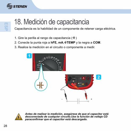
18. Medición de capacitancia Capacitancia es la habilidad de un componente de retener carga eléctrica.
1. Gire la perilla al rango de capacitancia ( )2. Conecte la punta roja a hFE, mA, TEMP y la negra a COM.3. Realice la medición en el circuito o componente a medir.
1
2
Antes de realizar la medición, asegúrese de que el capacitor está desconectado de cualquier circuito.Use la función de voltaje CD paraconfi rmar que el capacitor está descargado.
- +
COM
hFEmATEMP 10A
600VCAT III
MAX 10AFUSED
MAX 30 sec.every 15 min.
Hz
29
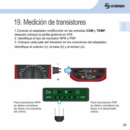
19. Medición de transistores1.Conecte el adaptador multifunción en las entradas COM y TEMP, después coloque la perilla giratoria en hFE.2. Identifi que el tipo de transistor NPN o PNP3. Coloque cada pata del transistor en los conectores del adaptador. Identifi que el colector (c), la base (b) y el emisor (e).
+
-
Para transistores NPN se deben considerar las letras a la izquierda del orifi cio.
Para transistores PNP se deben considerar las letras a la derechadel orifi cio.
30
Para evitar choque eléctrico o daños al instrumento, nunca
aplique más de 250 V CD o 250 V CA RMS entre la terminal hFE y la
terminal COM.
Antes de realizar la medición, asegúrese de que el transistor está
desconectado de cualquier circuito.
31
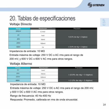
20. Tablas de especifi cacionesVoltaje Directo
Rango Precisión200mV
2V
20V
200V
600V
+- (0.5% de rdg + 2 digitos)
+- (0.8% de rdg + 2 digitos)
0.1mV
1mV
10mV
100mV
1V
Resolución
Impedancia de entrada: 10 MΩEntrada máxima de voltaje: 250 V DC o AC rms para el rango de 200 mV, y 600 V DC o 600 V AC rms para otros rangos.
Voltaje AlternoRango Precisión
2v
20V
200V
750V
+- (0.8% de rdg + 3 digitos)
+- (1.2% de rdg + 3 digitos)
1mV
10mV
100mV
1V
Resolución
Impedancia de entrada: 10 MΩEntrada máxima de voltaje: 250 V DC o AC rms para el rango de 200 mV, y 600 V DC o 600 V AC rms para otros rangos.Rango de frecuencia: 40 Hz-400 HzRespuesta: Promedio, calibrada en rms de onda sinusoidal.
V
600V
32
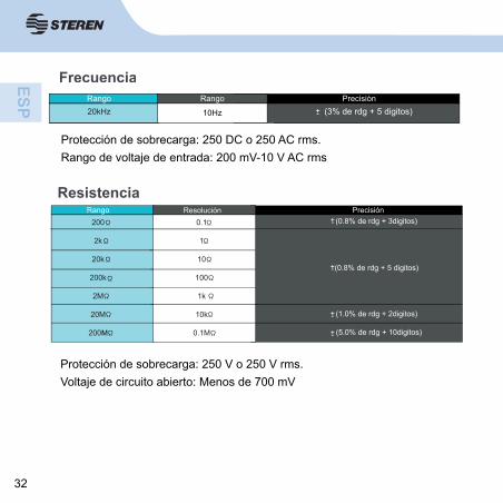
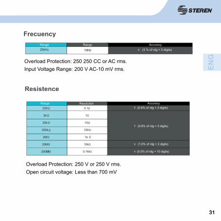
FrecuenciaRango Precisión20kHz +- (3% de rdg + 5 digitos)
Rango
10Hz
Protección de sobrecarga: 250 DC o 250 AC rms.Rango de voltaje de entrada: 200 mV-10 V AC rms
ResistenciaRango Precisión
200
2k
20k
200k
2M
20M
200m
+- (0.8% de rdg + 3digitos)
(0.8% de rdg + 5 digitos)+-
+- (1.0% de rdg + 2digitos)
(5.0% de rdg + 10digitos)+-
0.1
1
10
100
1k
10k
0.1M
Resolución
Protección de sobrecarga: 250 V o 250 V rms.Voltaje de circuito abierto: Menos de 700 mV
M
33
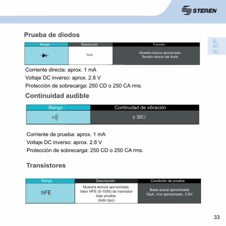
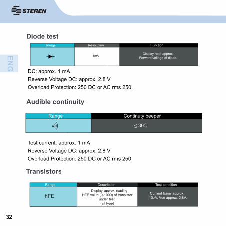
Prueba de diodosRango Función
Muestra lectura aproximada.Tensión directa del diodo.
Resolución
1mV
Corriente directa: aprox. 1 mAVoltaje DC inverso: aprox. 2.8 VProtección de sobrecarga: 250 CD o 250 CA rms.
Continuidad audibleRango Continudad de vibración
< 30
Corriente de prueba: aprox. 1 mAVoltaje DC inverso: aprox. 2.8 VProtección de sobrecarga: 250 CD o 250 CA rms.
Transistores
Rango
Muestra lectura aproximada.Tensión directa del diodo.
Rango Descripción Condición de prueba
hFEMuestra lectura apróximada.
Valor HFE (0-1000) de transistorbajo prueba.(todo tipo)
Base actual aproximada10 A, Vce aproximado. 2.8V.h
34
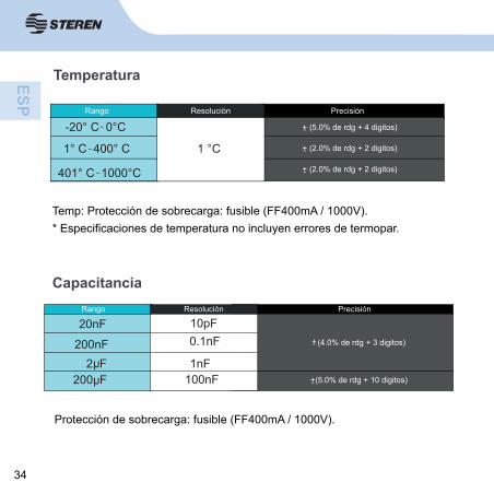
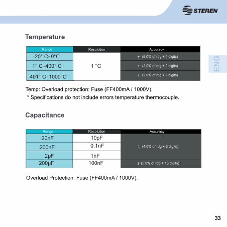
Temperatura
RangoRango Precisión
-20° C 0°C
1° C 400° C
401° C 1000°C
(5.0% de rdg + 4 digitos)+-
(2.0% de rdg + 2 digitos)+-
(2.0% de rdg + 2 digitos)+-
Resolución
1 °C
Temp: Protección de sobrecarga: fusible (FF400mA / 1000V).* Especifi caciones de temperatura no incluyen errores de termopar.
CapacitanciaRango Precisión
+- (4.0% de rdg + 3 digitos)
+- (5.0% de rdg + 10 digitos)
20nF
200nF2 F
200 F
hh
10pF0.1nF
1nF 100nF
Resolución
Protección de sobrecarga: fusible (FF400mA / 1000V).
35
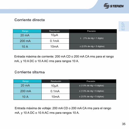
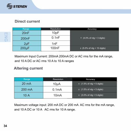
Corriente directa
Rango ResoluciónRango Precisión
20 mA
200 mA
10 A
(1% de rdg + 1 digito)+-
(2.0% de rdg + 5 digitos)+-10mA
10µA
0.1mA
Entrada máxima de corriente: 200 mA CD o 200 mA CA rms para el rango mA, y 10 A DC o 10 A AC rms para rangos 10 A.
Corriente alterna
RangoRango Precisión
20 mA
200 mA
10 A
(1.5% de rdg + 5 digitos)+-
(1.5% de rdg + 5 digitos)+-
(3.0% de rdg + 5 digitos)+-
0µA
0.1mA
10mA
Resolución
Entrada máxima de voltaje: 200 mA CD o 200 mA CA rms para el rango mA, y 10 A DC o 10 A AC rms para rangos 10 A.
1
36
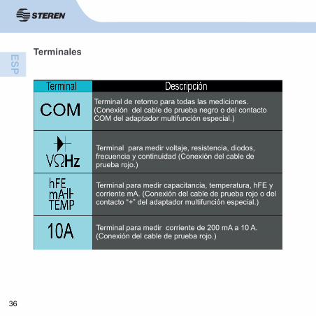
Terminales
Terminal de retorno para todas las mediciones. (Conexión del cable de prueba negro o del contacto COM del adaptador multifunción especial.)
Terminal para medir voltaje, resistencia, diodos, frecuencia y continuidad (Conexión del cable de prueba rojo.)
Terminal para medir capacitancia, temperatura, hFE y corriente mA. (Conexión del cable de prueba rojo o del contacto “+” del adaptador multifunción especial.)
Terminal para medir corriente de 200 mA a 10 A. (Conexión del cable de prueba rojo.)
37
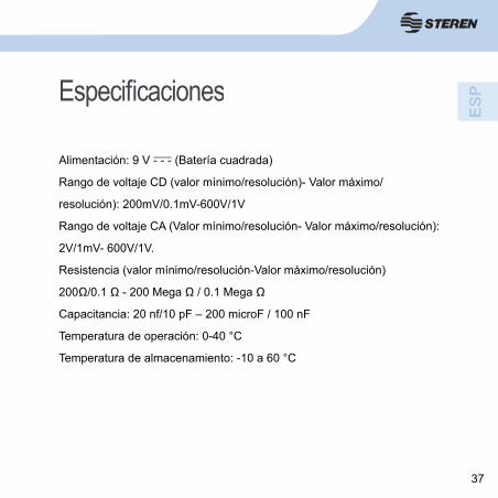
Especifi caciones
Alimentación: 9 V - - - (Batería cuadrada)
Rango de voltaje CD (valor mínimo/resolución)- Valor máximo/
resolución): 200mV/0.1mV-600V/1V
Rango de voltaje CA (Valor mínimo/resolución- Valor máximo/resolución):
2V/1mV- 600V/1V.
Resistencia (valor mínimo/resolución-Valor máximo/resolución)
200Ω/0.1 Ω - 200 Mega Ω / 0.1 Mega Ω
Capacitancia: 20 nf/10 pF – 200 microF / 100 nF
Temperatura de operación: 0-40 °C
Temperatura de almacenamiento: -10 a 60 °C
38
Producto: Multímetro digital con detector de voltajeModelo: MUL-288Marca: Steren
PÓLIZA DE GARANTÍAEsta póliza garantiza el producto por el término de un año en todas sus partes y mano de obra, contra cualquier defecto de fabricación y funcionamiento, a partir de la fecha de entrega.
CONDICIONES1.- Para hacer efectiva la garantía, presente esta póliza y el producto, en donde fue adquirido o en Electrónica Steren S.A. de C.V.2.- Electrónica Steren S.A de C.V. se compromete a reparar el producto en caso de estar defectuoso sin ningún cargo al consumidor. Los gastos de transportación serán cubiertos por el proveedor.3.- El tiempo de reparación en ningún caso será mayor a 30 días, contados a partir de la recepción del producto en cualquiera de los sitios donde pueda hacerse efectiva la garantía.4.- El lugar donde puede adquirir partes, componentes, consumibles y accesorios, así como hacer válida esta garantía es en cualquiera de las direcciones mencionadas posteriormente.
ESTA PÓLIZA NO SE HARÁ EFECTIVA EN LOS SIGUIENTES CASOS:1.- Cuando el producto ha sido utilizado en condiciones distintas a las normales.2.- Cuando el producto no ha sido operado de acuerdo con el instructivo de uso.3.- Cuando el producto ha sido alterado o reparado por personal no autorizado por Electrónica Steren S.A. de C.V.El consumidor podrá solicitar que se haga efectiva la garantía ante la propia casa comercial donde adquirió el producto. Si la presente garantía se extraviara, el consumidor puede recurrir a su proveedor para que le expida otra póliza, previa presentación de la nota de compra o factura respectiva.
DATOS DEL DISTRIBUIDORNombre del Distribuidor __________________________Domicilio ______________________________________Producto ______________________________________Marca ________________________________________Modelo _______________________________________Número de serie ________________________________Fecha de entrega ________________________________
ELECTRÓNICA STEREN S.A. DE C.V.Camarones 112, Obrero Popular, 02840, Del. Azcapotzalco, México, D.F. RFC: EST850628-K51STEREN PRODUCTO EMPACADO S.A. DE C.V.Biólogo Maximino Martínez No. 3408 Int. 2, 3 y 4, San Salvador Xochimanca, Del. Azcapotzalco, México, D.F. 02870, RFC: SPE941215H43ELECTRÓNICA STEREN DEL CENTRO, S.A. DE C.V.Rep. del Salvador 20 A y B, Centro, 06000, Del. Cuauhtémoc, México. D.F. RFC: ESC9610259N4ELECTRÓNICA STEREN DE GUADALAJARA, S.A.López Cotilla No. 51, Centro, 44100, Guadalajara, Jal. RFC: ESG810511HT6ELECTRÓNICA STEREN DE MONTERREY, S.A.Colón 130 Pte., Centro, 64000, Monterrey, N.L. RFC: ESM830202MF8ELECTRÓNICA STEREN DE TIJUANA, S.A. de C.V.Calle 2a, Juárez 7636, Centro, 22000, Tijuana, B.C.N. RFC: EST980909NU5
En caso de que su producto presente alguna falla, acuda al centro de distribución más cercano a su domicilio y en caso de tener alguna duda o pregunta por favor llame a nuestro Centro de Atención a Clientes, en donde con gusto le atenderemos en todo lo relacionado con su producto Steren.
Centro de Atención a Clientes01 800 500 9000
MUL-288
Voltage detector multitester
Instruction manual0715v
HOLD
20K
20
20
200
200
600600
200K
200
200
200n
20n
20m
200m10
10200m 20m
2TEMP
AhFE 20kHz
2
2K
2M 20M200M
200m
MS8260C
A
COM
Hz
hFEmATEMP
10A
600V
CAT III
MAX 10A
FUSED
MAX 30 sec.
every 15 min.
V0.1

22
Thank You on purchasing your new Steren product.
This manual includes all the feature operations and troubleshooting necessary to install and operate your new Steren´s VOLTAGE DETECTOR
MULTITESTER
Please review this manual thoroughly to ensure proper installation and operation of this product. For support, shopping,
and everything new at Steren, visit our website:
www.steren.com
MUL-288
VOLTAGE DETECTOR MULTITESTER
The instructions of this manual are for reference about the product. There may be differences due to updates.
Please check our web site (www.steren.com) to obtain the latest version of the instruction manual.
33
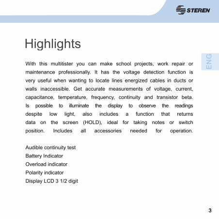
HighlightsWith this multitister you can make school projects, work repair or maintenance professionally. It has the voltage detection function is very useful when wanting to locate lines energized cables in ducts or walls inaccessible. Get accurate measurements of voltage, current,capacitance, temperature, frequency, continuity and transistor beta.Is possible to illuminate the display to observe the readings despite low light, also includes a function that returnsdata on the screen (HOLD), ideal for taking notes or switchposition. Includes all accessories needed for operation.
Audible continuity testBattery IndicatorOverload indicatorPolarity indicatorDisplay LCD 3 1/2 digit
44
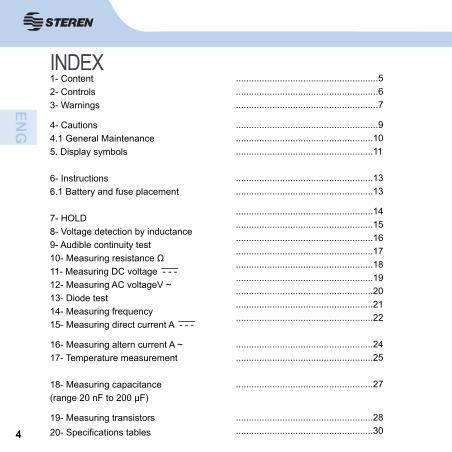
INDEX1- Content2- Controls3- Warnings
4- Cautions4.1 General Maintenance5. Display symbols
6- Instructions6.1 Battery and fuse placement
7- HOLD8- Voltage detection by inductance9- Audible continuity test10- Measuring resistance Ω11- Measuring DC voltage - - -12- Measuring AC voltageV ~13- Diode test14- Measuring frequency15- Measuring direct current A - - -
16- Measuring altern current A ~17- Temperature measurement
18- Measuring capacitance (range 20 nF to 200 μF)
19- Measuring transistors20- Specifi cations tables
.......................................................5
.......................................................6
.......................................................7
.......................................................9
.....................................................10
.....................................................11
.....................................................13
.....................................................13
.....................................................14
.....................................................15
.....................................................16
.....................................................17
.....................................................18
.....................................................19
.....................................................20
.....................................................21
.....................................................22
.....................................................24
.....................................................25
.....................................................27
.....................................................28
.....................................................30
55
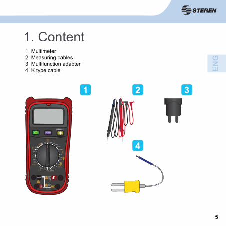
1. Content1. Multimeter2. Measuring cables3. Multifunction adapter4. K type cable
1 2 3
4HOLD
20K
20
20
200
200
600
600
200K200
200
200n
20n
20m
200m
1010
200m20m
2
TEMP
A hFE 20kHz
2
2K2M
20M200M
200m
MS8260C
A
COM Hz
hFEmATEMP 10A
600VCAT III
MAX 10AFUSED
MAX 30 sec.every 15 min.
66
2. Controls
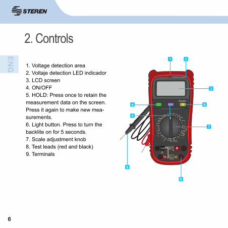
1. Voltage detection area2. Voltaje detection LED indicador3. LCD screen4. ON/OFF5. HOLD: Press once to retain the measurement data on the screen. Press it again to make new mea-surements.6. Light button. Press to turn thebacklite on for 5 seconds.7. Scale adjustment knob8. Test leads (red and black)9. Terminals
HOLD
20K
20
20
200
200
750
1000
200K200
200
200n
20n
20m
200m
1010
200m20m
2
TEMP
A hFE 20kHz
2
2K 2M20M
200M
200m
MS8260C
A
COM Hz
hFEmATEMP 10A
600VCAT III
MAX 10AFUSED
MAX 30 sec.every 15 min.
1 2
3
4
5
6
7
8
8
9
600600
77
3. Warnings
To avoid the risk of electric shock or damage to your person and possible damage to the meter or the equipment under test, observe the following warnings:- Remove the test leads before opening or removing the Meter’s battery compartment cover.- When servicing the Meter, use only the same models and spare parts identical to the original.- Before opening the instrument, remove all sources of power and ensure that you are not charged with static electricity as it can destroy internal components.- Any maintenance or repair work carried out with the meter should be performed by qualifi ed personnel, after taking into account the instructions in this manual.
88
3. Warnings- Before using the Meter inspect the case. Do not use if the cover or part of it has been removed. Check loss of plastic specially around the connectors.- Inspect the test leads for damaged insulation or exposure of metal parts. Inspect the test leads for continuity. Use only test leads included with the meter, replace the damaged ends with an identical model of the same electrical characteristics.- Do not apply more than the ratio of voltage marked on the meter, bet-ween terminals or between any terminal and earth.- The rotary switch should be placed upright and no overload range should be displayed during measurement, this prevents damage meter.- Use the proper terminals, function and range for your measurements.- Do not use or store the meter in an environment of high temperature, humidity, explosive, fl ammable or strong magnetic fi eld. Meter performance may deteriorate after being moistened or wet.- When using probes, keep fi ngers beyond the guards.- Disconnect circuit power and discharge all high-voltage capacitors before testing resistance, continuity, diodes, current or capacitance.
99
4. Cautions- Screen may become unstable or mark an error if the meter is used near noise generating equipment.- Only use the meter according to this instruction.- Use extreme caution when working with bare conductors or busbars.- Do not operate the Meter around explosive gas, vapor or dust.- Check meter operation by measuring a voltage already known.- Use the right terminals, functions and ranges for your measurements.- When the measurement range is not known, start with the highest.- Do not exceed the maximum input values shown in the charts.- Do not touch the terminals that are not in use when measuring circuits.- When making connections, connect the common test lead fi rst and then the live test lead and vice versa when unplugging, remove the live test lead fi rst and then the common test lead.- Before changing functions, disconnect the test leads from the tested circuit.-- Do not measure voltages greater than 600 V CAT III installations.(Category III is for measurements performed in installations of buildings.)- Do not operate the meter without the lid.
1010
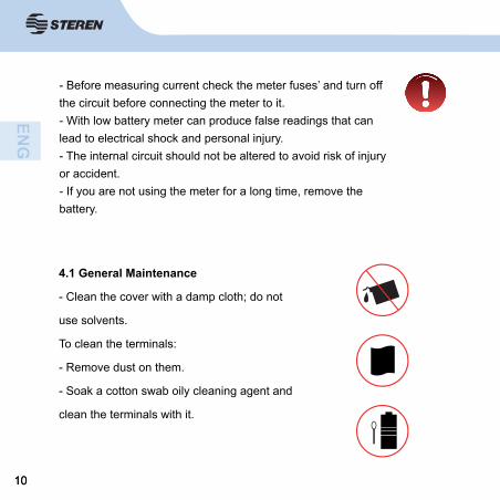
4.1 General Maintenance
- Clean the cover with a damp cloth; do not
use solvents.
To clean the terminals:
- Remove dust on them.
- Soak a cotton swab oily cleaning agent and
clean the terminals with it.
- Before measuring current check the meter fuses’ and turn off the circuit before connecting the meter to it.- With low battery meter can produce false readings that can lead to electrical shock and personal injury.- The internal circuit should not be altered to avoid risk of injury or accident.- If you are not using the meter for a long time, remove the battery.
1111
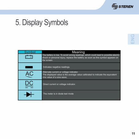
5. Display Symbols
Symbol MeaningThe battery is low. To avoid wrong readings, which could lead to possible electric shock or personal injury, replace the battery as soon as this symbol appears on the screen.
Indicates negative readings.
AC Alternate current or voltage indicator.The displayed value is the average value calibrated to indicate the equivalent rms value of a sine wave.
DC Direct current or voltage indicator.
The meter is in diode test mode
1212
hFE Gain factor (beta transistors)
1313
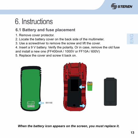
1. Remove cover protector.2. Locate the battery cover on the back side of the multimeter.3. Use a screwdriver to remove the screw and lift the cover.4. Insert a 9 V battery. Verify the polarity. Or in case, remove the old fuse and install a new one (FF400mA / 1000V or FF10A / 600V)5. Replace the cover and screw it back on.
When the battery icon appears on the screen, you must replace it.
6.1 Battery and fuse placement6. Instructions
1414
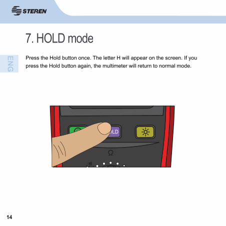
7. HOLD modePress the Hold button once. The letter H will appear on the screen. If you press the Hold button again, the multimeter will return to normal mode.
HOLD
1515
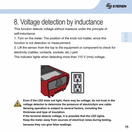
8. Voltage detection by inductanceThis function detects voltage without measure under the principle of self-inductance1. Turn on the meter. The position of the knob not matter, since this function is not detection or measurement.2. Lift the sensor from the top to the equipment or component to check for electricity (cables, contacts, sockets, etc.) part.The indicator lights when detecting more than 110 V (rms) voltage.
Even if the LED does not light, there may be voltage; do not trust in the voltage detector to determine the presence of electricityin one cable.Sensing operation is subject to several factors, including thethickness and type of insulation.If the terminal detects voltage, it is possible that the LED lights.Keep the meter away from sources of electrical noise during testing, because they can give false readings.
1616
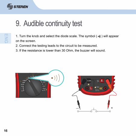
9. Audible continuity test1. Turn the knob and select the diode scale. The symbol ( ) will appear on the screen.2. Connect the testing leads to the circuit to be measured.3. If the resistance is lower than 30 Ohm, the buzzer will sound.
+
COM
hFEmATEMP 10A
600VCAT III
MAX 10AFUSED
MAX 30 sec.every 15 min.
Hz
20K
20
200
200K200
200
200n
20n
20m
TEMP
2
2K 2M20M
200M
200m
600
1717
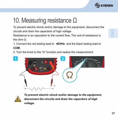
10. Measuring resistance ΩTo prevent electric shock and/or damage to the equipment, disconnect the circuits and drain the capacitors of high voltage.Resistance is an opposition to the current fl ow. The unit of resistance is the ohm Ω.1. Connect the red testing lead to ΩVHz and the black testing lead to COM.2. Turn the knob to the “Ω” function and realize the measurement.
To prevent electric shock and/or damage to the equipment, disconnect the circuits and drain the capacitors of high voltage.
1 2
+-
COM
hFEmATEMP 10A
600VCAT III
MAX 10AFUSED
MAX 30 sec.every 15 min.
Hz
1818
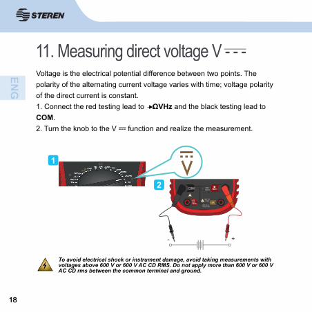
11. Measuring direct voltage V - - -Voltage is the electrical potential difference between two points. The polarity of the alternating current voltage varies with time; voltage polarity of the direct current is constant.1. Connect the red testing lead to ΩVHz and the black testing lead to COM.2. Turn the knob to the V --- function and realize the measurement.
To avoid electrical shock or instrument damage, avoid taking measurements with voltages above 600 V or 600 V AC CD RMS. Do not apply more than 600 V or 600 V AC CD rms between the common terminal and ground.
1
2
+-
COM
hFEmATEMP 10A
600VCAT III
MAX 10AFUSED
MAX 30 sec.every 15 min.
Hz
1919
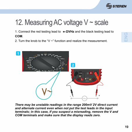
12. Measuring AC voltage V ~ scale1. Connect the red testing lead to ΩVHz and the black testing lead to COM.2. Turn the knob to the “V ~” function and realize the measurement.
There may be unstable readings in the range 200mV 2V direct current and alternate current even when not put the test leads in the input terminals; in this case, if you suspect a misreading, remove the V and COM terminals and make sure that the display reads zero.
1
2
+-
COM
hFEmATEMP 10A
600VCAT III
MAX 10AFUSED
MAX 30 sec.every 15 min.
Hz
600
600
2020
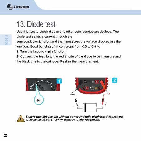
13. Diode testUse this test to check diodes and other semi-conductors devices. The diode test sends a current through the semiconductor junction and then measures the voltage drop across the junction. Good bonding of silicon drops from 0.5 to 0.8 V.1. Turn the knob to ( ) function.2. Connect the test tip to the red anode of the diode to be measure and the black one to the cathode. Realize the measurement.
Ensure that circuits are without power and fully discharged capacitors to avoid electrical shock or damage to the equipment.
1 2
+-
COM
hFEmATEMP 10A
600VCAT III
MAX 10AFUSED
MAX 30 sec.every 15 min.
Hz
2121
14. Measuring frequencyFrequency is the number of cycles to complete the signal voltage or current every second.1. Connect the red testing point to ΩVHz and the black testing point to COM.2. Turn the knob to the 20 kHz frequency.
To avoid electrical shock or damage to the equipment, do not measure frequency in high voltages (> 250 V).
1
2
+-
COM
hFEmATEMP 10A
600VCAT III
MAX 10AFUSED
MAX 30 sec.every 15 min.
Hz
20kHz
2222
15. Measuring direct current A - - -
To avoid damage to the meter or injury if the fuse blows,
never attempt a measurement on a live circuit where the open
circuit potential to ground is greater than 250 V, and check
the fuse before measuring.
Use the right terminals, functions and range for your
measurement. Never place the test leads in parallel with a
circuit or component when the cables are connected to the
current terminals.
Current is the fl ow of electrons through a conductor.

2323
1. Turn off the power to the circuit under test. Discharge all high-voltage capacitors.2. Connect the red lead to the hFEmA TEMP terminal for a maximum of 200 mA and “10 A” for up to 10 A; and black to COM terminal.
3. Turn the knob to the “ - - - A” function. 4. Break the circuit path to be measured. Connect the black wire to the more negative side of which broke the circuit and the red to the positive
side. (Reverse cables will give you a negative reading.)5. Turn on the power to the circuit under test and see the measurement.
If a “1” is in display, this indicates an over range, select a higher range.
+
COM
hFEmATEMP 10A
600VCAT III
MAX 10AFUSED
MAX 30 sec.every 15 min.
Hz
A

2424
16. Measuring alternating current (A ~)1. Connect the red testing point to 10 A and the black one to COM.2. Turn the knob to the “A~” function and realize the measurement.
Note: To measure smaller current scales, connect the red testing lead to hFEmA TEMP.
+
COM
hFEmATEMP 10A
600VCAT III
MAX 10AFUSED
MAX 30 sec.every 15 min.
Hz1
2
A
2525
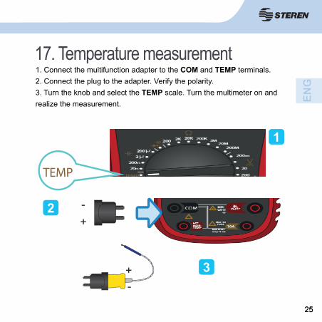
17. Temperature measurement1. Connect the multifunction adapter to the COM and TEMP terminals.2. Connect the plug to the adapter. Verify the polarity.3. Turn the knob and select the TEMP scale. Turn the multimeter on and realize the measurement.
1
2
3
TEMP
+-
+-
2626
To avoid electrical shock or instrument damage, never apply
more than 250 V or 250 V AC CD RMS between the terminal
° C and the COM terminal.
Avoid using the multimeter when voltages exceed 60 V DC or
24 V AC RMS.
To avoid damages or burns, do measurements temperature in
microwave ovens.
Note: Only makes measurements in ° C
2727
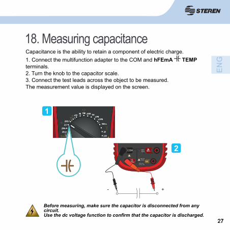
18. Measuring capacitance Capacitance is the ability to retain a component of electric charge.1. Connect the multifunction adapter to the COM and hFEmA TEMP terminals.2. Turn the knob to the capacitor scale. 3. Connect the test leads across the object to be measured. The measurement value is displayed on the screen.
Before measuring, make sure the capacitor is disconnected from any circuit.Use the dc voltage function to confi rm that the capacitor is discharged.
1
2
- +
COM
hFEmATEMP 10A
600VCAT III
MAX 10AFUSED
MAX 30 sec.every 15 min.
Hz
2828
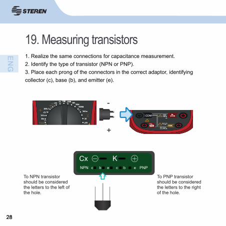
19. Measuring transistors1. Realize the same connections for capacitance measurement.2. Identify the type of transistor (NPN or PNP).3. Place each prong of the connectors in the correct adaptor, identifying collector (c), base (b), and emitter (e).
+
-
To NPN transistor should be considered the letters to the left of the hole.
To PNP transistor should be considered the letters to the right of the hole.
2929
To avoid electrical shock or instrument damage, never apply
more than 250 V or 250 V AC CD rms between the hFE terminal and
the COM terminal.
Before measuring, make sure the transistor is disconnected from
any circuit.
3030
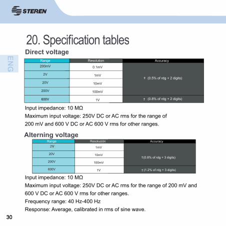
20. Specifi cation tablesDirect voltage
Input impedance: 10 MΩMaximum input voltage: 250V DC or AC rms for the range of200 mV and 600 V DC or AC 600 V rms for other ranges.
Range Accuracy200mV
2V
20V
200V
1000V
+- (0.5% of rdg + 2 digits)
+- (0.8% of rdg + 2 digits)
0.1mV
1mV
10mV
100mV
1V
Resolution
Alterning voltage
Input impedance: 10 MΩMaximum input voltage: 250V DC or AC rms for the range of 200 mV and 600 V DC or AC 600 V rms for other ranges.Frequency range: 40 Hz-400 HzResponse: Average, calibrated in rms of sine wave.
Range Accuracy2v
20V
200V
600V
+- (0.8% of rdg + 3 digits)
+- (1.2% of rdg + 3 digits)
1mV
10mV
100mV
1V
ResoluciónV
600V
3131
Frecuency
Overload Protection: 250 250 CC or AC rms.Input Voltage Range: 200 V AC-10 mV rms.
20kHz +- (3 % of rdg + 5 digits)Range AccuracyRango
10Hz
Resistence
Overload Protection: 250 V or 250 V rms.Open circuit voltage: Less than 700 mV
200
2k
20k
200k
2M
20M
200m
+- (0.8% of rdg + 3 digits)
(0.8% of rdg + 5 digits)+-
+- (1.0% of rdg + 2 digits)
(5.0% of rdg + 10 digits)+-
Range Accuracy0.1
1
10
100
1k
10k
0.1M
Resolution
M
3232
Diode test
DC: approx. 1 mAReverse Voltage DC: approx. 2.8 VOverload Protection: 250 DC or AC rms 250.
Range Function
Display read approx.Forward voltage of diode.
Resolution
1mV
Audible continuity
Test current: approx. 1 mAReverse Voltage DC: approx. 2.8 VOverload Protection: 250 DC or AC rms 250
Range Continuty beeper
< 30
Transistors
Rango
Muestra lectura aproximada.Tensión directa del diodo.
Range Description Test condition
hFEDisplay read approx.
HFE value (0-1000) of transistorunder test.(all type)
Base current approx.10 A, Vce approx. 2.8V.h
approx. readingCurrent base
3333
Temperature
Temp: Overload protection: Fuse (FF400mA / 1000V). * Specifi cations do not include errors temperature thermocouple.
RangoRange Accuracy
-20° C 0°C
1° C 400° C
401° C 1000°C
(5.0% of rdg + 4 digits)+-
(2.0% of rdg + 2 digits)+-
(2.0% of rdg + 2 digits)+-
Resolution
1 °C
Capacitance
Overload Protection: Fuse (FF400mA / 1000V).
Range Accuracy
+- (4.0% of rdg + 3 digits)
+- (5.0% of rdg + 10 digits)
20nF
200nF2 F
200 F
hh
10pF0.1nF
1nF 100nF
Resolution
3434
Direct current
Maximum Input Current: 200mA 200mA DC or AC rms for the mA range, and 10 A DC or AC rms 10 A to 10 A ranges
Range Accuracy
+- (4.0% of rdg + 3 digits)
+- (5.0% of rdg + 10 digits)
20nF
200nF2 F
200 F
hh
10pF0.1nF
1nF 100nF
Resolution
Altering current
Maximum voltage input: 200 mA DC or 200 mA AC rms for the mA range,and 10 A DC or 10 A AC rms for 10 A range.
RangoRange Accuracy
20 mA
200 mA
10 A
(1.5% of rdg + 5 digits)+-
(1.5% of rdg + 5 digits)+-
(3.0% of rdg + 5 digits)+-
0µA
0.1mA
10mA
Resolution
1
3535
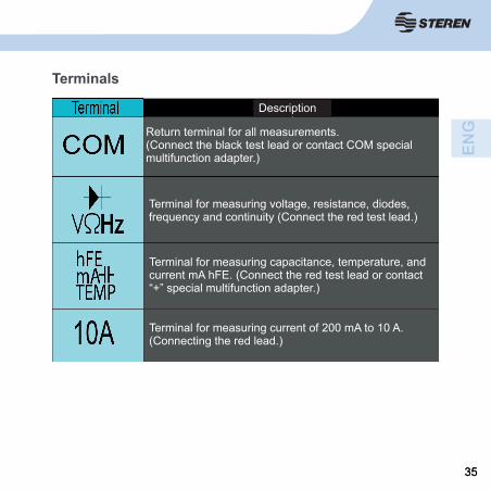
Return terminal for all measurements.(Connect the black test lead or contact COM special multifunction adapter.)
Terminal for measuring voltage, resistance, diodes,frequency and continuity (Connect the red test lead.)
Terminal for measuring capacitance, temperature, and current mA hFE. (Connect the red test lead or contact “+” special multifunction adapter.)
Terminal for measuring current of 200 mA to 10 A. (Connecting the red lead.)
Terminals
Description

3636
Specifi cations
Input: 9 V - - - (Battery square)
DC voltage range (minimum / resolution) - Maximum / resolution):
200mV / 0.1mV-600V / 1V
AC voltage range (minimum value / resolution-up / resolution Value):
2V / 1mV- 600V / 1V.
Resistance: (minimum / maximum resolution-value / resolution)
200Ω / 0.1 Ω - 200 Mega Ω / Ω 0.1 Mega
Capacitance: 20 nf / 10 pF - 200 microF / 100 nF
Operating temperature: 0-40 ° C
Storage temperature: -10 to 60 ° C
3737
WARRANTY
This Steren product is warranted under normal usage against defects in workmanship and materials to the original purchaser for one year from the date of purchase.
CONDITIONS
1. This warranty card with all the required information, invoice, product box or package, and product, must be presented when warranty service is required.2. If the product is in the warranty time, the company will repair it free of charge.3. The repairing time will not exceed 30 natural days, from the day the claim was received.4. Steren sell parts, components, consumables and accessories to customer, as well as warranty service, at any of the addresses mentioned later.
THIS WARRANTY IS VOID IN THE NEXT CASES:
If the product has been damaged by an accident, acts of God, mishandling, leaky batteries, failure to follow enclosed instructions, improper repair by unauthorized personnel, improper safe keeping, among others.
a) The consumer can also claim the warranty service in the purchase establishment.b) If you lose the warranty card, we can reissue it, if you show the invoice or purchase ticket.
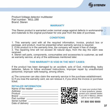
RETAILER INFORMATIONName of the retailerAddressProductBrandPart numberSerial numberDate of delivery
Product:Voltage detector multitesterPart number: MUL-288Brand: Steren
In case your product fails or have questions, please
contact your nearest dealer. If you are in Mexico, please
call to our Call Center.
01 800 500 9000

3838