
MANUAL DE USO Y MANTENIMIENTO USE AND MAINTENANCE INSTRUCTIONS - Bombas … · 2018-03-04 · norma...
72
SERIE RNI - RN MANUAL DE USO Y MANTENIMIENTO USE AND MAINTENANCE INSTRUCTIONS NOTICE D’UTILISATION ET D’ENTRETIEN ISO 9001 ISO 14001 UNE-EN 166002 RNI - RN -1037
Transcript of MANUAL DE USO Y MANTENIMIENTO USE AND MAINTENANCE INSTRUCTIONS - Bombas … · 2018-03-04 · norma...
SERIE RNI - RN
MANUAL DE USO Y MANTENIMIENTO
USE AND MAINTENANCE INSTRUCTIONS
NOTICE D’UTILISATION ET D’ENTRETIEN
ISO 9001ISO 14001 UNE-EN 166002
RNI - RN -1037

Bombas Ideal, S.A.
Índice
Introducción 4
Descripción y uso 5
Identificación 5
Garantía 6
Recepción del suministro 6
Almacenamiento 6
Manipulación 6
Montaje e instalación 7
Funcionamiento, puesta en marcha y paro 11
Gestión y controles 11
Montaje y desmontaje 13
Mantenimiento 14
Anomalias de funcionamiento 16
Anexos 51
Bombas Ideal, S.A. 4
INTRODUCCIÓN
Este manual de servicio está dirigido a los usuarios de bombas horizontales tipos RN y RNI. Contiene las
instrucciones de instalación, servicio y mantenimiento.
Antes de proceder a cualquier tipo de intervención, el usuario debe leer atentamente este manual y prestar
atención a cuantas sugerencias y recomendaciones se den en él, especialmente las que sean precedidas de
los siguientes símbolos de seguridad:
La no observancia de estas instrucciones, puede exponer a las personas a riesgos
importantes para su salud.
La no observancia de estas instrucciones, puede exponer a las personas a riesgos de
origen eléctrico.
ATENCIÓN Las instrucciones identificadas con este mensaje, indican su importancia para una correcta
instalación, utilización y mantenimiento.
Las instrucciones contenidas en este manual cumplen con la Directiva de la CEE sobre Máquinas nº89/399,
así como sus sucesivas modificaciones.
Con el objeto de mejorar el resultado final de sus productos, Bombas Ideal S.A. se reserva el derecho de
modificar el contenido del presente manual y/o el propio producto sin necesidad de avisar previamente a sus
clientes.
El incumplimiento de las sugerencias y recomendaciones de este manual, así como la incorrecta utilización
o la manipulación no autorizada del producto, invalida totalmente la responsabilidad de Bombas Ideal S.A.,
por los posibles daños causados, ya sean personales o materiales.
Ante cualquier duda respecto del producto, su utilización, mantenimiento o reparación deberán contactar con:
Bombas Ideal S.A.
Polig. Ind. Mediterráneo C/Cid nº 8
Tfno. 34 961 402 143 Fax 34 961 402 131
46560 Massalfassar – Valencia – Spain
El manual se suministra junto con la bomba y debe estar próximo al lugar de la instalación, debidamente
protegido, para que pueda ser consultado por los usuarios en caso de necesidad.
1.
Bombas Ideal, S.A. 5
DESCRIPCIÓN Y USO
Descripción.
Las bombas RN y RNI, en sus dimensiones y características hidráulicas, se ajustan a los requisitos de la norma
DIN 24255 y extensión.
Las bombas RN y RNI, son bombas centrifugas horizontales de rodete único, aspiración axial e impulsión
vertical hacia arriba, con patas de fijación en la voluta o caracol que está abierto por el lado de acoplamiento
permitiendo el desmontaje de las partes giratorias sin mover las tuberías de aspiración e impulsión de la
instalación, con la excepción de los modelos RN-PF en los que es necesario desmontar el cuerpo de aspiración
para tener acceso al rodete.
El rodete o impulsor es del tipo cerrado. El sentido de giro es el horario (a derechas) situándose del lado del
acoplamiento. La caja prensa alojada en la tapa cuerpo, está preparada para recibir empaquetadura trenzada
de la calidad adecuada al líquido que se bombea, así como para montar cierre mecánico de dimensiones según
norma DIN 24960.
El eje de accionamiento está soportado por dos rodamientos rígidos de bolas, lubricados por grasa o aceite.
Pueden ser accionadas por motor térmico o por motor eléctrico, montados sobre una bancada común y unidas
por un acoplamiento semielástico.
Uso.
Las bombas RN y RNI son adecuadas para elevación y trasiego de líquidos en industrias, instalaciones de
riego, minas, construcción, abastecimiento de poblaciones, instalaciones de aire acondicionado, equipos
contra-incendios, etc.
En su versión estándar se han diseñado para el trasiego de agua limpia hasta una temperatura máxima de
100ºC.
Bajo pedido, se pueden suministrar con configuraciones especiales, capaces de bombear distintos tipos de
líquidos y temperaturas hasta un máximo de 160º C.
En ningún caso:
� Se ubicarán en locales clasificados con riesgo de explosión.� Se utilizarán para el trasiego de líquidos inflamables.
IDENTIFICACIÓN
Las bombas RN y RNI, incorporan sobre el soporte de rodamientos una placa metálica en la que se indican
los datos siguientes:
TIPO: identificación del modelo de bomba.
Nº : número de fabricación.
Cuando en el contrato o pedido se requiera un punto de trabajo determinado, caudal y altura, se situará en la
placa junto a las indicaciones:
Q (m3 / h) : caudal en metros cúbicos por hora.
H (m) : altura manométrica en metros.
2.2.
2.
2.1.
3.
GARANTÍA
Bombas Ideal S.A., garantiza las bombas, por un período de 12 meses desde la fecha de entrega, contra todo
defecto de materiales y de fabricación, de acuerdo con lo indicado en sus condiciones generales de venta.
El incumplimiento de las sugerencias y recomendaciones de este manual, así como la incorrecta utilización o
la manipulación no autorizada del producto, invalida totalmente la garantía.
La garantía excluye el desgaste por uso, la utilización incorrecta, la reparación o sustitución de la pieza
defectuosa por el usuario o por personal no cualificado sin la autorización expresa de Bombas Ideal S.A.
RECEPCIÓN DEL SUMINISTRO
A la recepción del suministro se debe verificar que:
� El embalaje no ha sufrido deterioro durante el transporte. En caso contrario efectuar inmediatamente
la correspondiente reclamación al transportista.� El material suministrado coincide con las especificaciones del pedido.� El material no ha sufrido ningún daño durante el transporte.� Junto con el material se incluye el Manual Técnico.
ATENCIÓN Cualquier anomalía detectada debe ser comunicada de forma inmediata a Bombas Ideal S.A.
ALMACENAMIENTO
Las bombas se almacenarán en zonas aireadas y exentas de humedades.
Para períodos cortos de almacenamiento, se protegerán las partes mecanizadas con un aceite o producto
anticorrosivo.
Si el tiempo de permanencia en almacén es mas prolongado, se tomarán las precauciones necesarias para
evitar la corrosión de la bomba mediante el empleo de un producto anticorrosivo, procediendo además al cierre
de los orificios de aspiración e impulsión. Con una periodicidad de 15 días se girará a mano el eje para evitar
posibles agarrotamientos.
ATENCIÓN Asegurar que el motor térmico o eléctrico no sea expuesto a agentes atmosféricos, no
compatibles con su grado de protección, que puedan producirle daños.
Antes de almacenar una bomba que recientemente ha sido instalada deberemos proceder a su limpieza (no
utilizar productos derivados de hidrocarburos) y posterior secado con aire.
MANIPULACIÓN
Para la manipulación de los equipos se han de utilizar sistemas de elevación y transporte
adecuados y conformes con las normativas de seguridad.
Las bombas en versión eje libre se han de manipular utilizando como punto de elevación la boca de impulsión,
para posicionarla si es necesario utilizar la boca de aspiración y el soporte eje. Los modelos RNI disponen de
un ojal para su alzado.
El motor eléctrico se debe manipular utilizando el o los puntos de amarre previstos al efecto y que generalmente
se trata de una anilla situada en la parte superior de la carcasa (para motores con patas).
Bombas Ideal, S.A. 6
4.
5.
6.
7.
Bombas Ideal, S.A. 7
Cuando se trate de motores térmicos consultar el manual que acompaña al mismo.
Para manipular el conjunto bomba motor utilizar una eslinga que pase por la base de la bancada de manera
que se asegure la estabilidad durante la elevación y desplazamiento. En ningún caso utilizar la anilla situada
sobre motor o bomba.
8.1.- Cimentación
La cimentación será horizontal, firme y consistente y tendrá las dimensiones adecuadas para soportar todoel peso del equipo y absorber las vibraciones que se puedan producir durante el funcionamiento.
La cimentación se realizará en dos fases. La primera fase de la cimentación será al menos 20mm más bajaque su altura final. Se dejaran unas mangas en el lugar preciso en el que van a ir situados los pernos deanclaje de la bancada.
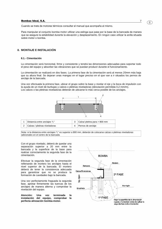
Una vez efectuada la primera fase, ubicar el grupo sobre la base y nivelar el eje y la boca de impulsión conla ayuda de un nivel de burbujas y calzos o pletinas niveladoras (desviación permitida 0,2 mm/m).Los calzos o las pletinas niveladoras deberán de ubicarse lo más cerca posible de los anclajes.
1 Distancia entre anclajes “L” 3 Calza/ pletina para > 800 mm
2 Calzas / pletinas niveladoras 4 Pernos de anclaje
Nota: si la distancia entre anclajes “L” es superior a 800 mm, deberán de colocarse calzas o pletinas niveladoras adicionales en el centro de la bancada.
Con el grupo nivelado, deberá de quedar unaseparación superior a 20 mm entre labancada y la superficie de la base pararealizar correctamente la segunda fase de lacimentación.
Efectuar la segunda fase de la cimentaciónrellenando de mortero los anclajes hasta elnivel superior de la bancada. El morterodeberá de tener la consistencia adecuadapara garantizar que no se produce laformación de cavidades bajo la bancada.
Una vez perfectamente fraguada la segundafase, apretar firmemente las tuercas de losanclajes de manera alterna y comprobar lanivelación del equipo.
Atención: Una vez terminada lainstalación del equipo, comprobar laperfecta alineación bomba-motor.
Bombas Ideal, S.A. 8
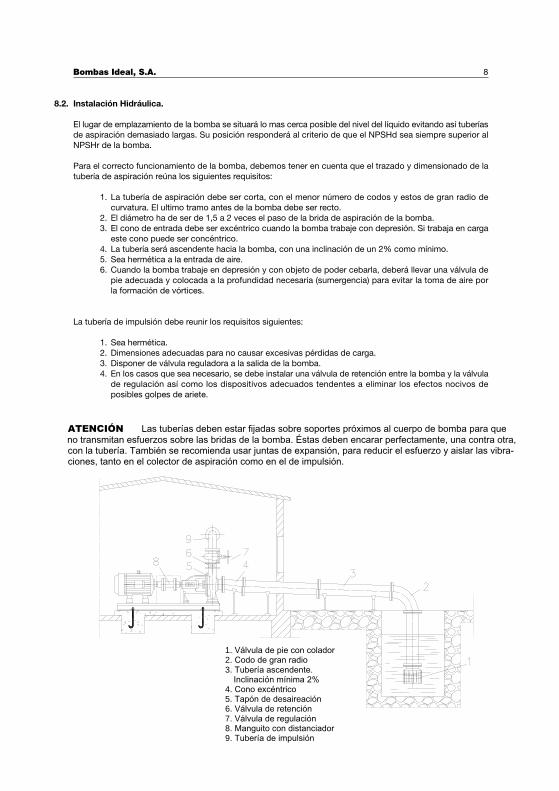
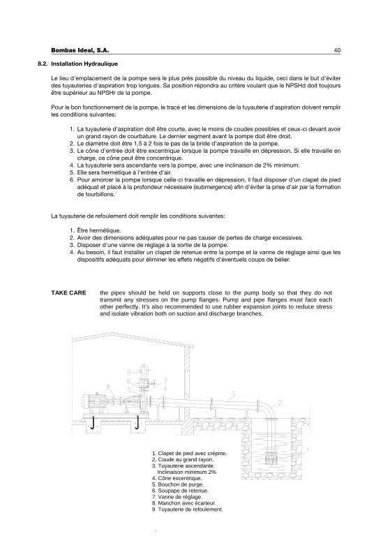
ATENCIÓN Las tuberías deben estar fijadas sobre soportes próximos al cuerpo de bomba para que no transmitan esfuerzos sobre las bridas de la bomba. Éstas deben encarar perfectamente, una contra otra,con la tubería. También se recomienda usar juntas de expansión, para reducir el esfuerzo y aislar las vibra-ciones, tanto en el colector de aspiración como en el de impulsión.
1. Válvula de pie con colador2. Codo de gran radio3. Tubería ascendente.
Inclinación mínima 2%4. Cono excéntrico5. Tapón de desaireación6. Válvula de retención7. Válvula de regulación8. Manguito con distanciador9. Tubería de impulsión
Instalación Hidráulica.
El lugar de emplazamiento de la bomba se situará lo mas cerca posible del nivel del líquido evitando así tuberías
de aspiración demasiado largas. Su posición responderá al criterio de que el NPSHd sea siempre superior al
NPSHr de la bomba.
Para el correcto funcionamiento de la bomba, debemos tener en cuenta que el trazado y dimensionado de la
tubería de aspiración reúna los siguientes requisitos:
1. La tubería de aspiración debe ser corta, con el menor número de codos y estos de gran radio de
curvatura. El ultimo tramo antes de la bomba debe ser recto.
2. El diámetro ha de ser de 1,5 a 2 veces el paso de la brida de aspiración de la bomba.
3. El cono de entrada debe ser excéntrico cuando la bomba trabaje con depresión. Si trabaja en carga
este cono puede ser concéntrico.
4. La tubería será ascendente hacia la bomba, con una inclinación de un 2% como mínimo.
5. Sea hermética a la entrada de aire.
6. Cuando la bomba trabaje en depresión y con objeto de poder cebarla, deberá llevar una válvula de
pie adecuada y colocada a la profundidad necesaria (sumergencia) para evitar la toma de aire por
la formación de vórtices.
La tubería de impulsión debe reunir los requisitos siguientes:
1. Sea hermética.
2. Dimensiones adecuadas para no causar excesivas pérdidas de carga.
3. Disponer de válvula reguladora a la salida de la bomba.
4. En los casos que sea necesario, se debe instalar una válvula de retención entre la bomba y la válvula
de regulación así como los dispositivos adecuados tendentes a eliminar los efectos nocivos de
posibles golpes de ariete.
8.2.
Alineación del grupo.
Se realiza en nuestras instalaciones, pero se debe revisar una vez se han conexionado las tuberías y antes de
poner en marcha el grupo.
ATENCIÓN Verificar que el sentido de giro del motor coincide con el sentido de giro de la bomba.
El acoplamiento semielástico debe estar perfectamente alineado. Un mal alineamiento
puede provocar un desgaste de los elementos elásticos del acoplamiento (flectores), del
cierre mecánico de la bomba y rodamientos del motor. Puede también generar vibraciones
y dañar el eje.
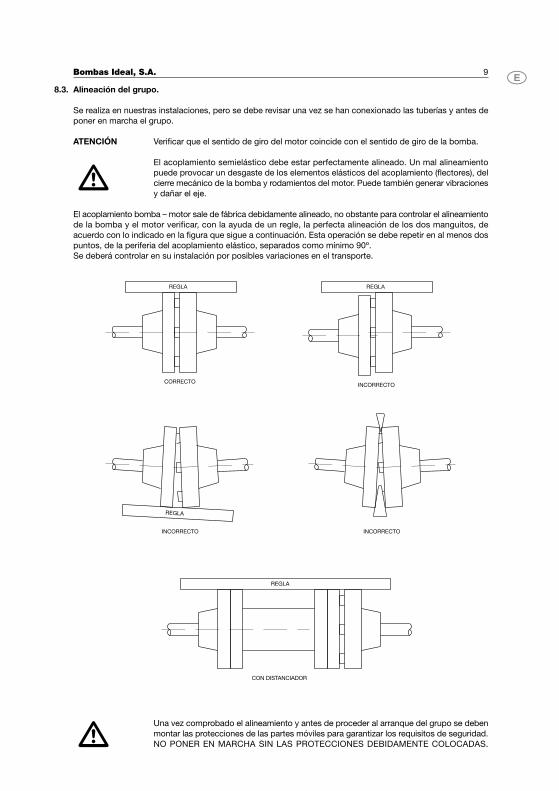
El acoplamiento bomba – motor sale de fábrica debidamente alineado, no obstante para controlar el alineamiento
de la bomba y el motor verificar, con la ayuda de un regle, la perfecta alineación de los dos manguitos, de
acuerdo con lo indicado en la figura que sigue a continuación. Esta operación se debe repetir en al menos dos
puntos, de la periferia del acoplamiento elástico, separados como mínimo 90º.
Se deberá controlar en su instalación por posibles variaciones en el transporte.
Una vez comprobado el alineamiento y antes de proceder al arranque del grupo se deben
montar las protecciones de las partes móviles para garantizar los requisitos de seguridad.
NO PONER EN MARCHA SIN LAS PROTECCIONES DEBIDAMENTE COLOCADAS.
Bombas Ideal, S.A. 9
8.3.
REGLA
CORRECTO
REGLA
REGLA
REGLA
INCORRECTO
INCORRECTO INCORRECTO
CON DISTANCIADOR
Conexiones eléctrica.
Las conexiones eléctricas se deben realizar por personal cualificado.
Antes de realizar el conexionado de los motores, comprobar que las partes eléctricas en
las que operaremos no están conectadas con la red de alimentación.
Los cables de tierra (color amarillo-verde) deben conectarse al circuito de tierra de la
instalación antes de conectar los restantes conductores.
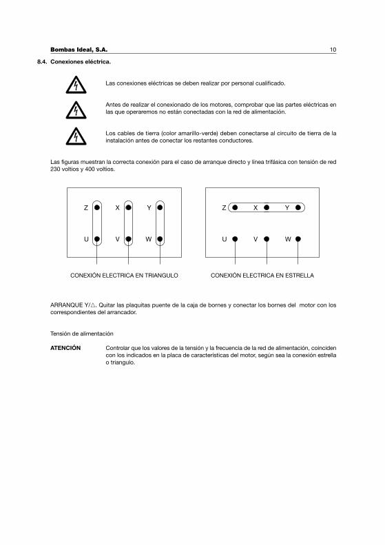
Las figuras muestran la correcta conexión para el caso de arranque directo y línea trifásica con tensión de red
230 voltios y 400 voltios.
ARRANQUE Y/�. Quitar las plaquitas puente de la caja de bornes y conectar los bornes del motor con los
correspondientes del arrancador.
Tensión de alimentación
ATENCIÓN Controlar que los valores de la tensión y la frecuencia de la red de alimentación, coinciden
con los indicados en la placa de características del motor, según sea la conexión estrella
o triangulo.
Bombas Ideal, S.A. 10
8.4.
Z
U
X
V
Y
W WVU
Z X Y
CONEXIÓN ELECTRICA EN TRIANGULO CONEXIÓN ELECTRICA EN ESTRELLA
Bombas Ideal, S.A. 11
FUNCIONAMIENTO, PUESTA EN MARCHA Y PARO
El funcionamiento de las bombas centrífugas del tipo RN y RNI es simple y seguro. No se debe utilizar una
bomba para un servicio distinto para el cual ha sido preparada. Si las condiciones en la instalación han variado,
deberá ponerlo en conocimiento de Bombas Ideal S.A. o de alguno de sus servicios técnicos, con la finalidad
de determinar los cambios necesarios para adecuarla a las nuevas exigencias.
Puesta en Marcha.
Antes de la puesta en marcha se tendrán en cuenta las siguientes indicaciones:
1. Comprobar el perfecto cebado de la bomba y tubería, el fluido debe desbordar la instalación para
garantizar que se ha eliminado el aire, especialmente el contenido en la tubería de aspiración.
2. La empaquetadura debe estar perfectamente colocada y apretada suavemente.
3. Comprobar con la mano que el eje gira fácilmente.
4. Comprobar la alineación del grupo de acuerdo con lo descrito en 8.3.
5. Verificar que el sentido de giro es coincidente con el indicado por la flecha que está situada en el
cuerpo de bomba.
6. En el caso de que la lubricación sea por aceite, comprobar nivel de llenado de la caja de rodamientos.
7. En el caso de cajas prensa refrigeradas, se comprobará la correcta circulación del líquido refrigerante.
8. Comprobar que se han montado todas las protecciones de las partes móviles.
La primera puesta en marcha, una vez efectuadas todas las comprobaciones , debe realizarse con la válvula
de impulsión cerrada, para reducir al mínimo el consumo de la bomba. Cuando se haya alcanzado la velocidad
de régimen, se abrirá lentamente la válvula, observando al mismo tiempo la variación del consumo, hasta la
total apertura de la misma. En régimen normal, el consumo, medido en amperios no debe superar al que se
indica en la placa del motor.
Paro de la bomba.
Para proceder a la parada del equipo, la válvula reguladora deberá llevarse a la misma posición, que la mantenida
durante la puesta en marcha. Podríamos efectuar la parada con la válvula de regulación abierta en el caso de
que la instalación esté dotada con dispositivo anti-ariete.
Controlar que la deceleración del motor sea normal y una vez se haya parado cerrar los circuitos auxiliares.
Para períodos largos de parada de los equipos, se debe vaciar por completo la bomba y las tuberías, para
evitar los riesgos de helada durante el invierno y la posible oxidación de los elementos mecánicos que se pueda
originar por el líquido estancado.
GESTION Y CONTROLES
El funcionamiento de las bombas centrífugas es sencillo y seguro no requiriendo un control exhaustivo, no
obstante para garantizar una correcta funcionalidad es importante tener en cuenta tanto en el primer momento
del arranque como después de un período prolongado de funcionamiento las siguientes indicaciones:
1. El funcionamiento debe ser silencioso y exento de vibraciones. Controlar, transcurridas las primeras
200 horas de utilización, la perfecta alineación del equipo bomba – maquina motriz de acuerdo con
lo descrito en 8.3.- Alineación del grupo.
2. Verificar que el caudal y la presión de servicio se corresponden con los determinados en los campos
de trabajo (ver la documentación técnica pertinente de Bombas Ideal S.A.).
3. Para los equipos con motor eléctrico, controlar que la corriente absorbida (consumo en amperios)
no supere los valores indicados en la placa de características del motor.
4. El calor producido por el frotamiento de la empaquetadura con el eje (en el caso de bombas
suministradas con empaquetadura) se elimina por refrigeración con el mismo líquido bombeado, para
lo cual debemos garantizar un goteo leve. Si el goteo es elevado y no puede reducirse mediante el
9.
9.1.
9.2.
10.
apriete del prensa estopas será necesario será necesario sustituir la estopada de acuerdo con lo
descrito en el apartado Mantenimiento.
5. Si la caja prensa es del tipo refrigerada, se comprobará que el líquido refrigerante cumple su misión.
Tener en cuenta que la diferencia de las temperaturas de entrada y de salida debe oscilar entre
10/15ºC.
Lubricación.
Las bombas RN y RNI se pueden suministrar con lubricación por grasa o por aceite de acuerdo con la
clasificación siguiente en función del modelo de soporte utilizado. Para identificar que tipo de soporte lleva
cada bomba ver la tabla de INTERCAMBIABILIDAD.
� RN con soporte N-250 y N-300. Se suministran con rodamientos estancos engrase de por vida, por
lo que no requieren control respecto del engrase.� RN con soportes N-400 y N-500. Se suministran con rodamientos lubricados por grasa. Bajo pedido
se pueden suministrar con lubricación por aceite.� RN con soportes N-550, N-600 y N-800. Se suministran con rodamientos lubricados por aceite.
ATENCIÓN Las bombas RN que se suministran con rodamientos lubricados por aceite disponen de
una varilla con una marca que indica el nivel de llenado.
� RNI con soportes N-25A, N-25B, N-35, N-35G, N-45, N-45DA, 55, 60 y 75. Se suministran con
rodamientos lubricados por grasa.� RNI con soporte N25h, N35h y N-35H . Se suministran con rodamientos lubricados por aceite.
ATENCIÓN Las bombas RNI que se suministran con rodamientos lubricados por aceite, disponen
en el soporte de rodamientos de un visor que debe estar cubierto por el aceite hasta la
mitad.
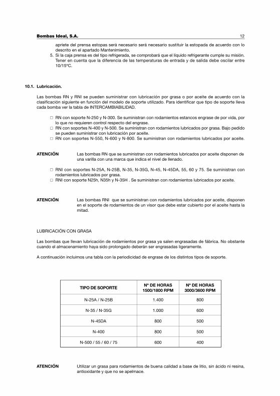
LUBRICACIÓN CON GRASA
Las bombas que llevan lubricación de rodamientos por grasa ya salen engrasadas de fábrica. No obstante
cuando el almacenamiento haya sido prolongado deberán ser engrasadas ligeramente.
A continuación incluimos una tabla con la periodicidad de engrase de los distintos tipos de soporte.
ATENCIÓN Utilizar un grasa para rodamientos de buena calidad a base de litio, sin ácido ni resina,
antioxidante y que no se apelmace.
Bombas Ideal, S.A. 12
10.1.
TIPO DE SOPORTENº DE HORAS
1500/1800 RPMNº DE HORAS
3000/3600 RPM
N-25A / N-25B
N-35 / N-35G
N-45DA
N-400
N-500 / 55 / 60 / 75
1.400
1.000
800
800
600
800
600
500
500
400
Bombas Ideal, S.A. 13
LUBRICACIÓN POR ACEITE
Cuando la lubricación se realice por aceite, se recomienda que después de las primeras doscientas horas de
funcionamiento se renueve completamente. Los siguientes cambios se deben realizar cada 1.000 horas de
servicio o como mínimo una vez al año, siempre que la temperatura ambiente sea inferior a 50º C. Para
temperaturas ambientes superiores a 50º C acortar el período de renovación del aceite.
ATENCIÓN Utilizar aceites de viscosidad 4 a 6 ENGLER a 40º C
MONTAJE Y DESMONTAJE
En el caso de que sea necesario desmontar la bomba para realizar alguna operación de mantenimiento o
reparación se procederá de acuerdo con lo descrito a continuación.
Detrás del nombre de las diferentes piezas aparece el número con el que han sido designadas tanto en las
secciones contenidas en este manual como en el listado de denominación de piezas.
Generalmente el cuerpo de bomba nº 379 no requiere intervención, por lo que quedará unido a las tuberías
de aspiración e impulsión. En primer lugar procederemos al vaciado del líquido contenido en las tuberías y en
el cuerpo de bomba aflojando el tapón vaciado bomba nº 42. Procederemos también al vaciado del aceite,
cuando se trate de bombas lubricadas por aceite, aflojando el tapón vaciado soporte nº 41 del soporte
rodamientos nº 789.
A continuación podremos soltar el motor de la bancada y dejar sitio para el desmontaje de las partes giratorias
de la bomba. En el supuesto de que el acoplamiento elástico sea con espaciador, será suficiente soltar el
mismo.
Soltar a continuación los tornillos nº 51 (en las RN soportes N-250, N-400 y N-500) que fijan la tapa cuerpo
nº 812 al cuerpo de bomba nº 379, en el caso de las RNI se deben soltar las tuercas nº 96. De esta manera
se desmontará el conjunto formado por el soporte rodamientos nº 789 con la tapa cuerpo nº 812 y el rodete
nº 726.
Para separar el rodete nº 726 del conjunto, en el caso de las RN, aflojar el prisionero y la tuerca sujeción rodete
nº 828. En el caso de las RNI aflojar la tuerca sujeción rodete nº 828 y quitar la arandela tope rodete nº 236.
La chaveta ajuste rodete nº 22 debe ser guardada en lugar adecuado para que quede protegida de golpes y
oxidaciones.
Soltando los tornillos nº 33 (en el caso de las RN) o las tuercas nº 95 (en el caso de las RNI) que fijan el soporte
rodamientos nº 789 a la tapa cuerpo nº 812 podremos desmontar el cierre mecánico nº 63. En el caso de las
RN con empaquetadura desmontaremos el prensa estopas nº 653 la empaquetadura nº 32 y la propia tapa
cuerpo nº 812.
Aflojando los tornillos nº 34 de las dos tapas rodamiento nº 810 y 811 podremos desmontarlas y separar el eje
nº450 con los rodamientos nº 29 y 30 de su alojamiento en el soporte rodamientos nº 789. Utilizar procedimientos
habituales para separar los rodamientos del eje.
Todas las piezas deben ser tratadas con esmero, engrasándolas y guardándolas en lugar adecuado hasta que
se vuelvan a montar. Para la limpieza de los rodamientos y sus alojamientos debe emplearse gasolina, benzol
o producto de características similares.
Después de reparar o sustituir las piezas defectuosas se procederá al montaje de la bomba procediendo de
manera inversa a lo descrito en este apartado.
11.
(ISO VG68, SAE20, SAE10W 30)
AGIP Acer 68SHELL Tellos 68ESSO Nuto 68
MOBIL DTE 26TEXACO Rando HD 68
ACEITES RECOMENDADOS:
Bombas Ideal, S.A. 14
12.- MANTENIMIENTO ATENCIÓN Las reparaciones y las operaciones de mantenimiento deben ser realizadas por
personal cualificado que conozca la mecánica, las normas de seguridad y la hidráulica. Las operaciones de mantenimiento extraordinario o reparaciones importantes deben ser realizadas por talleres especializados. 12.1.- Desmontaje. Atenerse a lo descrito en el apartado 11.- MONTAJE Y DESMONTAJE. 12.2.- Sustitución del aceite en el soporte de rodamientos.
Quitar el tapón vaciado soporte, cuidando que el aceite se deposite en un recipiente adecuado.
Introducir el aceite nuevo, una vez se haya colocado el tapón vaciado soporte (tener en cuenta lo descrito en 10.1.- Lubricación)
El aceite retirado debe ser tratado de acuerdo con la normativa vigente para el tratamiento de residuos.
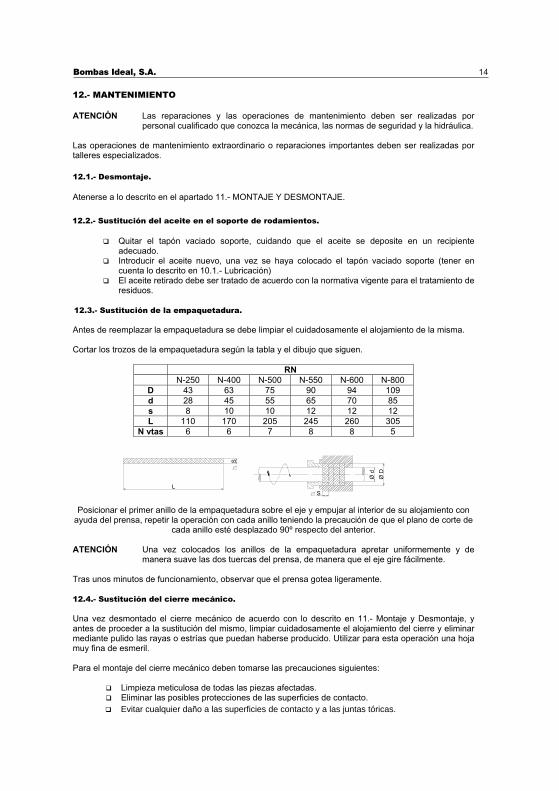
12.3.- Sustitución de la empaquetadura. Antes de reemplazar la empaquetadura se debe limpiar el cuidadosamente el alojamiento de la misma. Cortar los trozos de la empaquetadura según la tabla y el dibujo que siguen.
RN N-250 N-400 N-500 N-550 N-600 N-800
D 43 63 75 90 94 109 d 28 45 55 65 70 85 s 8 10 10 12 12 12 L 110 170 205 245 260 305
N vtas 6 6 7 8 8 5
Posicionar el primer anillo de la empaquetadura sobre el eje y empujar al interior de su alojamiento con ayuda del prensa, repetir la operación con cada anillo teniendo la precaución de que el plano de corte de
cada anillo esté desplazado 90º respecto del anterior. ATENCIÓN Una vez colocados los anillos de la empaquetadura apretar uniformemente y de
manera suave las dos tuercas del prensa, de manera que el eje gire fácilmente. Tras unos minutos de funcionamiento, observar que el prensa gotea ligeramente. 12.4.- Sustitución del cierre mecánico. Una vez desmontado el cierre mecánico de acuerdo con lo descrito en 11.- Montaje y Desmontaje, y antes de proceder a la sustitución del mismo, limpiar cuidadosamente el alojamiento del cierre y eliminar mediante pulido las rayas o estrías que puedan haberse producido. Utilizar para esta operación una hoja muy fina de esmeril. Para el montaje del cierre mecánico deben tomarse las precauciones siguientes:
Limpieza meticulosa de todas las piezas afectadas. Eliminar las posibles protecciones de las superficies de contacto.
S
Ø D
Ø d
L
S
� Evitar cualquier daño a las superficies de contacto y a las juntas tóricas.
Bombas Ideal, S.A. 15
12.5.- Sustitución de los flectores de goma del acoplamiento elástico. Para sustituir los flectores de goma, seguir la siguiente secuencia: 1. Desmontar la protección.2. Desmontar el motor de la base de acuerdo con lo descrito en 11.- Montaje y desmontaje.3. Desplazar el motor hasta conseguir que se desacoplen las dos semijuntas. 4. Cambiar los flectores de goma desgastados. 5. Volver a ensamblar el conjunto teniendo en cuenta lo descrito en 8.3-Alineación del Grupo, y verificar
dicho alineamiento transcurrido un corto periodo de tiempo.
No arrancar el grupo sin haber montado todas las protecciones de las partes móviles quegarantizan los requisitos de seguridad.
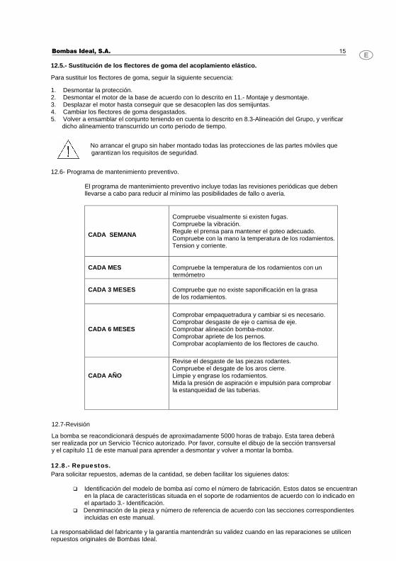
12.6- Programa de mantenimiento preventivo.
El programa de mantenimiento preventivo incluye todas las revisiones periódicas que deben llevarse a cabo para reducir al mínimo las posibilidades de fallo o avería.
CADA SEMANA
Compruebe visualmente si existen fugas.Compruebe la vibración. Regule el prensa para mantener el goteo adecuado.Compruebe con la mano la temperatura de los rodamientos.Tension y corriente.
CADA MES
Compruebe la temperatura de los rodamientos con un termómetro
CADA 3 MESES
Compruebe que no existe saponificación en la grasade los rodamientos.
CADA 6 MESES
Comprobar empaquetradura y cambiar si es necesario.Comprobar desgaste de eje o camisa de eje. Comprobar alineación bomba-motor. Comprobar apriete de los pernos.Comprobar acoplamiento de los flectores de caucho.
CADA AÑO
Revise el desgaste de las piezas rodantes. Compruebe el desgate de los aros cierre. Limpie y engrase los rodamientos. Mida la presión de aspiración e impulsión para comprobarla estanqueidad de las tuberias.
12.7-Revisión La bomba se reacondicionará después de aproximadamente 5000 horas de trabajo. Esta tarea deberáser realizada por un Servicio Técnico autorizado. Por favor, consulte el dibujo de la sección transversaly el capítulo 11 de este manual para aprender a desmontar y volver a montar la bomba.
12.8.- Repuestos. Para solicitar repuestos, ademas de la cantidad, se deben facilitar los siguienes datos:
� Identificación del modelo de bomba así como el número de fabricación. Estos datos se encuentran en la placa de características situada en el soporte de rodamientos de acuerdo con lo indicado enel apartado 3.- Identificación.
� Denominación de la pieza y número de referencia de acuerdo con las secciones correspondientesincluidas en este manual.
La responsabilidad del fabricante y la garantía mantendrán su validez cuando en las reparaciones se utilicen repuestos originales de Bombas Ideal.
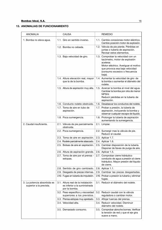
ANOMALIAS DE FUNCIONAMIENTO
Bombas Ideal, S.A. 16
13.
ANOMALIA CAUSA REMEDIO
1.1. Giro en sentido inverso.
1.2. Bomba no cebada.
1.3. Baja velocidad de giro.
1.4. Altura elevación real, mayor
que la de la bomba.
1.5. Altura de aspiración muy alta.
1.6. Conducto rodete obstruido.
1.7. Toma de aire en tubo de
aspiración.
1.8. Poca sumergencia.
1. Bomba no eleva agua.
2.1. Válvula de pie parcialmente
obstruida.
2.2. Poca sumergencia.
2.3. Toma de aire en aspiración.
2.4. Rodete parcialmente atascado.
2.5. Bolsas de aire en aspiración.
2.6. Altura de aspiración grande.
2.7. Toma de aire por el prensa -
estopas.
2.8. Sentido de giro cambiado.
2.9. Desgaste de piezas internas.
2.10. Fugas en tubería de impulsión.
3.1. Altura real de la instalación
es inferior a la suministrada
por la bomba.
3.2. Peso específico y viscosidad
superiores a los previstos.
3.3. Prensa estopas muy apretado.
3.4. Velocidad alta.
3.5. Demasiado consumo.
1.1. Cambio conexiones motor eléctrico.
Cambio posición motor de explosión.
1.2. Válvula de pie pierde. Pérdidas en
juntas o tubería de aspiración.
Revisar estos elementos.
1.3. Comprobar la velocidad con un
tacómetro, motor de explosión
acelerar.
Motor eléctrico. Averiguar el motivo
que provoca esa baja velocidad
(consumo excesivo o frecuencia
baja).
1.4. Aumentar la velocidad de giro de
la bomba o aumentar el diámetro del
rodete.
1.5. Acercar la bomba al nivel del agua.
Cambiar la bomba por otra de menor
NPSHr.
Reducir pérdidas en la tubería de
aspiración.
1.6. Desatascar los conductos del rodete.
1.7. Probar a presión, la tubería de
aspiración, incluyendo la bomba y
observar cualquier escape de líquido.
1.8. Prolongar la tubería de aspiración
aumentando la sumergencia.
2.1. Limpiar.
2.2. Sumergir mas la válvula de pie.
Reducir el caudal.
2.3. Aplicar 1.7.
2.4. Aplicar 1.6.
2.5. Cambiar disposición de la tubería.
Disponer de llaves de purga de aire.
2.6. Aplicar 1.5.
2.7. Comprobar cierre hidráulico
conducto de agua a presión al cierre
hidráulico. Mayor presión del líquido
de cierre.
2.8. Aplicar 1.1.
2.9. Cambiar las piezas desgastadas.
2.10. Probar a presión la tubería y eliminar
fugas.
3.1. Reducir el diámetro del rodete.
3.2. Reducir caudal con la válvula
reguladora o cambiar motor.
3.3. Aflojar tuercas del prensa.
3.4. Reducir velocidad. Disminuir
diámetro del rodete.
3.5. Comprobar abroche bornes. Verificar
la tensión de red y que el eje gira
suave a mano.
2. Caudal insuficiente.
3. La potencia absorbida es
superior a la prevista.
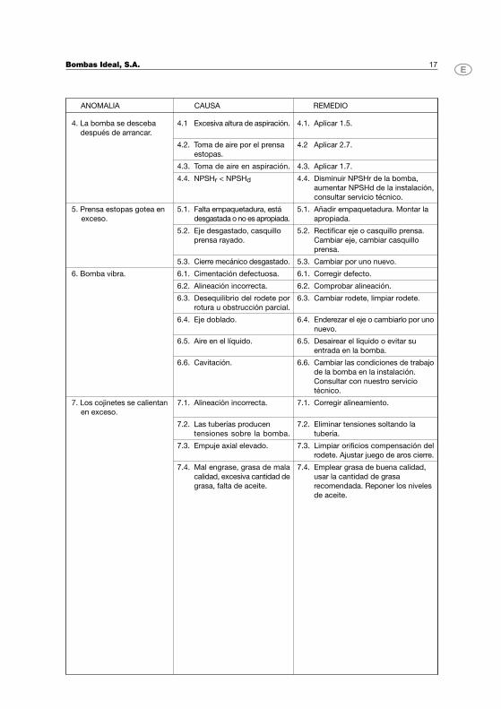
Bombas Ideal, S.A. 17
ANOMALIA CAUSA REMEDIO
4.1 Excesiva altura de aspiración.
4.2. Toma de aire por el prensa
estopas.
4.3. Toma de aire en aspiración.
4.4. NPSHr < NPSHd
5.1. Falta empaquetadura, está
desgastada o no es apropiada.
5.2. Eje desgastado, casquillo
prensa rayado.
5.3. Cierre mecánico desgastado.
4. La bomba se desceba
después de arrancar.
6.1. Cimentación defectuosa.
6.2. Alineación incorrecta.
6.3. Desequilibrio del rodete por
rotura u obstrucción parcial.
6.4. Eje doblado.
6.5. Aire en el líquido.
6.6. Cavitación.
7.1. Alineación incorrecta.
7.2. Las tuberías producen
tensiones sobre la bomba.
7.3. Empuje axial elevado.
7.4. Mal engrase, grasa de mala
calidad, excesiva cantidad de
grasa, falta de aceite.
7. Los cojinetes se calientan
en exceso.
5. Prensa estopas gotea en
exceso.
6. Bomba vibra.
4.1. Aplicar 1.5.
4.2 Aplicar 2.7.
4.3. Aplicar 1.7.
4.4. Disminuir NPSHr de la bomba,
aumentar NPSHd de la instalación,
consultar servicio técnico.
5.1. Añadir empaquetadura. Montar la
apropiada.
5.2. Rectificar eje o casquillo prensa.
Cambiar eje, cambiar casquillo
prensa.
5.3. Cambiar por uno nuevo.
6.1. Corregir defecto.
6.2. Comprobar alineación.
6.3. Cambiar rodete, limpiar rodete.
6.4. Enderezar el eje o cambiarlo por uno
nuevo.
6.5. Desairear el líquido o evitar su
entrada en la bomba.
6.6. Cambiar las condiciones de trabajo
de la bomba en la instalación.
Consultar con nuestro servicio
técnico.
7.1. Corregir alineamiento.
7.2. Eliminar tensiones soltando la
tubería.
7.3. Limpiar orificios compensación del
rodete. Ajustar juego de aros cierre.
7.4. Emplear grasa de buena calidad,
usar la cantidad de grasa
recomendada. Reponer los niveles
de aceite.

NOTAS / NOTES
Bombas Ideal, S.A.
Index
Introduction 20
Description and use 21
Identification 21
Guarantee 22
Reception of the goods 22
Storage 22
Manipulation 23
Setup and installation 23
Running and controls 27
Handling and controls 27
Assembly and dismantling 29
Maintenance 30
Operating anomalies 32
Annexes 51
INTRODUCTION
This service manual is intended for users of type RN and RNI horizontal pumps. It contains the instructions for
installation, service and maintenance.
Before proceeding to do any kind of work on the equipment, users should read this manual carefully and pay
attention to any suggestions and tips given in it, particularly the ones preceded by the following safety symbols:
Failure to observe these instructions may expose people to serious danger for their health.
Failure to observe these instructions may expose people to electrical risks.
TAKE NOTE Any instructions preceded by this message are of great importance for proper installation,
use and maintenance.
The instructions contained in this manual comply with EEC directive nº89/399 on machines, as well as its
subsequent modifications.
In order to improve the final result of its products, Bombas Ideal S.A. reserves the right to modify the content
of this manual and/or the product itself with no need to inform its customers beforehand.
Failure to comply with the suggestions and recommendations in this manual, as well as improper use or non-
authorised handling of the product, shall fully release Bombas Ideal S.A. from any liability as regards possible
damage caused, whether this be personal or material.
In the event of any doubt about the product, its use, maintenance or repair, please contact:
Bombas Ideal S.A.
Polig. Ind. Mediterráneo C/Cid nº 8
Tel. 34 961 402 143 Fax 34 961 402 131
46560 Massalfassar – Valencia – Spain
The manual is supplied along with the pump and should be kept close to the point of installation, duly protected
so that this can be consulted by users when required.
Bombas Ideal, S.A. 20
1.
Bombas Ideal, S.A. 21
DESCRIPTION AND USE
Description
RN and RNI pumps conform to the requisites of DIN standard 24255 and extension as per their sizes and
hydraulic characteristics.
Pumps RN and RNI are horizontal en suction centrifugal pumps with single impeller. Feet are
casted together with the pump casing wich is open at the back to allow the rotating parts been dismantled
without disturbing the suction and delivery pipes of the system, except for models RN-PF, in which it is necessary
to dismount the suction body to have access to the impeller.
The impeller is closed type. The rotation direction is clockwise (to the right) viewed from coupling side. The
sealing box built into the casing cover is prepared to accept packing, with different types depending on the
liquid being pumped. Mechanical seals according to DIN 24960 standard can also be assembled.
The drive shaft is held by two rigid ball bearings, lubricated either by grease or oil.
Pump can be driven by a diesel engine or electric motor, set on a common bedplate and joined by a semi-
elastic coupling.
Use
RN and RNI pumps are appropriate for lifting and moving liquids in industries, irrigation systems, mines, building,
urban supply, air conditioning installations, fire-fighting equipment, etc.
In their standard version they have been designed for moving clean water with temperature up to 100º C.
Upon request, special configurations can be supplied for different liquids and temperatures up to 160º C.
Do not under any circumstances:
� Locate the systems in premises classified as involving an explosion risk.� Use these for moving inflammable liquids.
IDENTIFICATION
RN and RNI pumps have a metal plate on the bearing support on which the following data is stated:
TYPE: identification of the pump model.
Nº : manufacturing number.
When a specific working point, flow & head, is specified in the contract or order, the following details will appear
on the plate :
Q (m3 / h) : flow in cubic metres per hour.
H (m) : manometric head in metres.
2.2.
2.
2.1.
3.
GUARANTEE
Pumps from Bombas Ideal S.A., have a guarantee period of 12 months from delivery date, against any flaw in
materials and manufacture, according to the general sales terms.
Failure to comply with the suggestions and recommendations in this manual, as well as any improper use or
non-authorised handling of the product, will completely invalidate the guarantee.
The guarantee excludes wear and tear through use, improper use, repair or replacement of the faulty part by
the user or by unqualified staff without the express consent of Bombas Ideal S.A.
RECEPTION OF THE GOODS
On reception of the goods please check that:
� The packaging has not undergone any damage during transport. Otherwise immediately make the
relevant claim to the forwarder.� The material supplied coincides with the order specifications.� The material has not undergone any damage during transport.� The Technical Manual is included with the material.
TAKE NOTE Bombas Ideal S.A. should immediately be informed of any anomaly found.
STORAGE
The pumps should be stored in well-ventilated zones free of damp.
For short storage periods the machined parts should be protected with an oil or anti-corrosion product.
If the pump is to be left for longer periods in the store, precautions should be taken to prevent the pump from
corroding by using an anti-corrosion product, also proceeding to cover up the suction and delivery flanges.
Turn the shaft by hand every 15 days to prevent any possible seizing up.
TAKE NOTE Make sure that the diesel engine or electric motor is not exposed to atmospheric agents
not compatible with its degree of protection which might cause damage to this.
Before storing a pump, which has recently been installed, proceed to clean and then air-dry it (do not used
hydrocarbide-based products).
Bombas Ideal, S.A. 22
4.
5.
6.
Bombas Ideal, S.A. 23
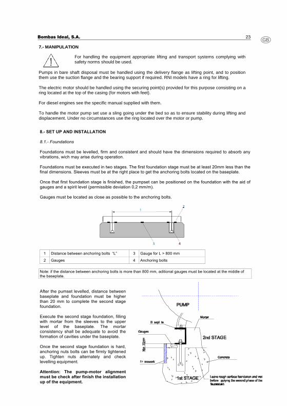
7.- MANIPULATION
For handling the equipment appropriate lifting and transport systems complying with safety norms should be used.
Pumps in bare shaft disposal must be handled using the delivery flange as lifting point, and to position them use the suction flange and the bearing support if required. RNI models have a ring for lifting. The electric motor should be handled using the securing point(s) provided for this purpose consisting on a ring located at the top of the casing (for motors with feet). For diesel engines see the specific manual supplied with them. To handle the motor pump set use a sling going under the bed so as to ensure stability during lifting and displacement. Under no circumstances use the ring located over the motor or pump. 8.- SET UP AND INSTALLATION 8.1.- Foundations Foundations must be levelled, firm and consistent and should have the dimensions required to absorb any vibrations, wich may arise during operation. Foundations must be executed in two stages. The first foundation stage must be at least 20mm less than the final dimensions. Sleeves must be at the right place to get the anchoring bolts located on the baseplate. Once that first foundation stage is finished, the pumpset can be positioned on the foundation with the aid of gauges and a spirit level (permissible deviation 0,2 mm/m). Gauges must be located as close as possible to the anchoring bolts.
1 Distance between anchoring bolts “L” 3 Gauge for L > 800 mm
2 Gauges 4 Anchoring bolts Note: if the distance between anchoring bolts is more than 800 mm, aditional gauges must be located at the middle of the baseplate. After the pumset levelled, distance between baseplate and foundation must be higher than 20 mm to complete the second stage foundation. Execute the second stage foundation, filling with mortar from the sleeves to the upper level of the baseplate. The mortar consistency shall be adequate to avoid the formation of cavities under the baseplate. Once the second stage foundation is hard, anchoring nuts bolts can be firmly tightened up. Tighten nuts alternately and check levelling equipment. Attention: The pump-motor alignment must be check after finish the installation up of the equipment.
Bombas Ideal, S.A. 24
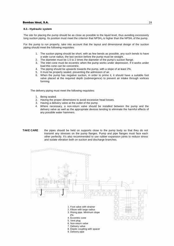
1. Foot valve with strainer 2. Elbow with large radius 3. Rising pipe. Minimum slope
2% 4. Eccentric cone 5. Vent plug 6. Non-return valve 7. Delivery valve 8. Elastic coupling with spacer 9. Delivery pipe
TAKE CARE the pipes should be held on supports close to the pump body so that they do not transmit any stresses on the pump flanges. Pump and pipe flanges must face each other perfectly. It’s also recommended to use rubber expansion joints to reduce stress and isolate vibration both on suction and discharge branches.
8.2.- Hydraulic system The site for placing the pump should be as close as possible to the liquid level, thus avoiding excessively long suction piping. Its position must meet the criterion that NPSHd is higher than the NPSHr of the pump. For the pump to run properly, take into account that the layout and dimensional design of the suction piping should meet the following requisites:
1. The suction piping should be short, with as few bends as possible, any such bends to have a wide curve radius, the last section before the pump must be straight.
2. The diameter must be 1.5 to 2 times the diameter of the pump’s suction flange. 3. The inlet cone must be eccentric when the pump works under depression. If it works under
load this cone can be concentric. 4. The piping should be upwards towards the pump, with a slope of at least 2%. 5. It must be properly sealed, preventing the admission of air. 6. When the pump has negative suction, in order to prime it, it should have a suitable foot
valve placed at the required depth (submergence) to prevent air intake through vortices forming.
The delivery piping must meet the following requisites:
1. Being sealed. 2. Having the proper dimensions to avoid excessive head losses. 3. Having a delivery valve at the outlet of the pump. 4. Where necessary, a non-return valve should be installed between the pump and the
delivery valve as well as the appropriate devices tending to eliminate the harmful effects of any possible water hammers.
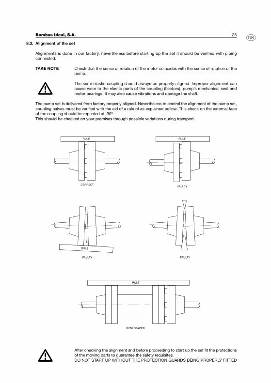
Alignment of the set
Alignments is done in our factory, nevertheless before starting up the set it should be verified with piping
connected.
TAKE NOTE Check that the sense of rotation of the motor coincides with the sense of rotation of the
pump.
The semi-elastic coupling should always be properly aligned. Improper alignment can
cause wear to the elastic parts of the coupling (flectors), pump’s mechanical seal and
motor bearings. It may also cause vibrations and damage the shaft.
The pump set is delivered from factory properly aligned. Nevertheless to control the alignment of the pump set,
coupling halves must be verified with the aid of a rule of as explained bellow. This check on the external face
of the coupling should be repeated at 90º.
This should be checked on your premises through possible variations during transport.
After checking the alignment and before proceeding to start up the set fit the protections
of the moving parts to guarantee the safety requisites.
DO NOT START UP WITHOUT THE PROTECTION GUARDS BEING PROPERLY FITTED
Bombas Ideal, S.A. 25
8.3.
RULE
CORRECT
RULE
RULE
RULE
FAULTY
FAULTY FAULTY
WITH SPACER
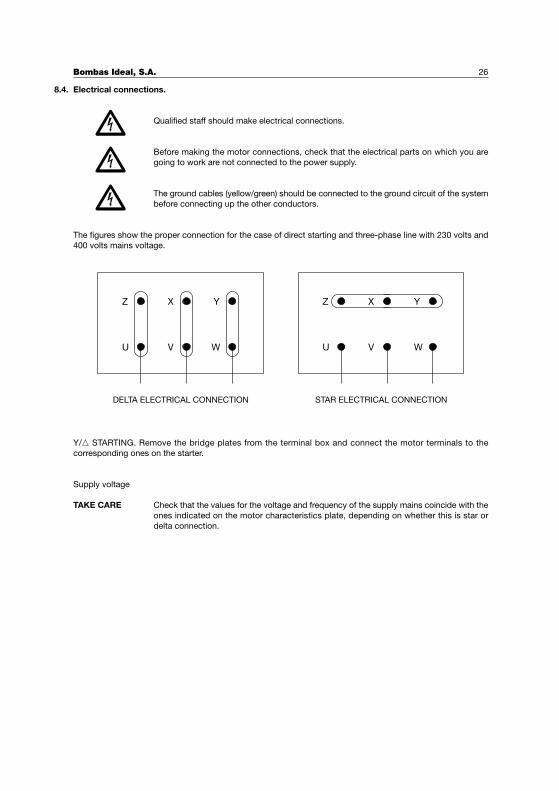
Electrical connections.
Qualified staff should make electrical connections.
Before making the motor connections, check that the electrical parts on which you are
going to work are not connected to the power supply.
The ground cables (yellow/green) should be connected to the ground circuit of the system
before connecting up the other conductors.
The figures show the proper connection for the case of direct starting and three-phase line with 230 volts and
400 volts mains voltage.
Y/� STARTING. Remove the bridge plates from the terminal box and connect the motor terminals to the
corresponding ones on the starter.
Supply voltage
TAKE CARE Check that the values for the voltage and frequency of the supply mains coincide with the
ones indicated on the motor characteristics plate, depending on whether this is star or
delta connection.
Bombas Ideal, S.A. 26
8.4.
Z
U
X
V
Y
W WVU
Z X Y
DELTA ELECTRICAL CONNECTION STAR ELECTRICAL CONNECTION
Bombas Ideal, S.A. 27
RUNNING, STARTING AND STOPPING
The operation of centrifugal pumps as RN, RNI and RNE is a simple and safe matter. Pump should not be used
for any purpose other than the one it was prepared for. If the conditions in the installation have varied, Bombas
Ideal S.A. or one of its technical services should be informed, in order to determine what changes might be
required to adapt to the new requirements.
Starting up.
Before starting up the following points should be taken into account:
1. Check the proper priming of the pump and pipelines, as the fluid should overflow the system to ensure
that all the air has been vented, especially any contained in the suction piping.
2. The packing should be properly placed and gently tightened.
3. Check that the shaft turns easily with your hand.
4. Check the alignment of the set in as described in 8.3.
5. Make sure that the sense of rotation coincides with the direction of the arrow located on the pump
body.
6. In the case of oil lubrication, check the filling level of the bearing box.
7. In the event of cooled sealing boxes, check the proper circulation of the cooling liquid.
8. Check that all the guards for the moving parts have been properly fitted.
For the first start up, after making all the checks, this should be done with the drive valve closed, to reduce
the consumption of the pump as far as possible. When the running speed has been reached, the valve should
slowly be opened, observing at the same time the variation in consumption, until this opens completely. In
normal operation the consumption, measured in amperes, should not be over what is stated on the motor plate.
Stopping the pump
To stop the pump, the delivery valve should be returned to the original position as before the start up. When
installation has a anti-water hammer device there is no need to close the delivery valve for stopping the pump.
Check that motor deceleration is normal and after it has completely stopped close the auxiliary circuits.
When the equipment is to be idle for long periods, the pump and piping should be completely drained, to
prevent the risks of frost during the winter and any possible rusting of the mechanical items that might be
caused through trapped liquid.
HANDLING AND CONTROLS
Centrifugal pumps performance is simple and safe and does not require any exhaustive checking, though to
guarantee proper operation it is important to take the following points into account both the first time this is
started up and after a long period running:
1. Operation should be silent and vibration-free. After the first 200 hours’ use, check proper alignment
of the pump-drive set as described in 8.3.- Alignment of the set.
2. Check that the flow and service pressure match what is determined in the work fields (see the relevant
technical documentation from Bombas Ideal S.A.).
3. For equipment with electrical motors, check that the input current (consumption in amperes) is not
over the values stated in the motor characteristics plate.
4. The heat produced by friction between the packing and the shaft (in the case of pumps supplied with
packing) is removed by cooling with the same liquid as is pumped through, for which purpose a slight
drip should be ensured. If the dripping is too high and cannot be reduced by tightening the stuffing
box, the packing will have to be replaced as described in the Maintenance section.
9.
9.1.
9.2.
10.
5. For externally cooled stuffing box should be checked that the cooling liquid is doing its job. Bear in
mind that the difference between input and output temperatures should range between 10/15º C.
Lubrication
RN, RNI and RNE pumps can be supplied with lubrication by grease or by oil in accordance with the following
classification depending on the support type. To identify which type of support is fitted on each pump see the
INTERCHANGEABLILITY TABLE.
� RN with N-250 and N-300 support. Supplied with sealed bearings, greased for life, so no check is
required as regards lubrication.� RN with N-400 and N-500 supports. Supplied with grease-lubricated bearings. These can be supplied
with oil lubrication under request.� RN with N-550, N-600 and N-800 supports. Supplied with oil-lubricated bearings.
TAKE NOTE The RN pumps supplied with bearings lubricated by oil have an oil stick with a mark
indicating the filling level.
� RNI with N-25A, N-25B, N-35, N-35G, N-45, N-45DA, 55, 60 and 75 supports. Supplied with grease-
ubricated bearings.� RNI with N25h, N35h y N-35H supports. Supplied with oil-lubricated bearings.
TAKE CARE The RNI and RNE pumps supplied with oil-lubricated bearings have a oil glass in the
bearing support which should be covered with the oil up to half way up.
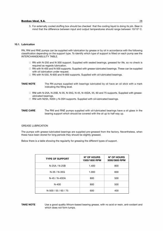
GREASE LUBRICATION
The pumps with grease-lubricated bearings are supplied pre-greased from the factory. Nevertheless, when
these have been stored for long periods they should be slightly greased.
Below there is a table showing the regularity for greasing the different types of support.
TAKE NOTE Use a good quality lithium-based bearing grease, with no acid or resin, anti-oxidant and
which does not form lumps.
Bombas Ideal, S.A. 28
10.1.
TYPE OF SUPPORTNº OF HOURS
1500/1800 RPMNº OF HOURS
3000/3600 RPM
N-25A / N-25B
N-35 / N-35G
N-45 / N-45DA
N-400
N-500 / 55 / 60 / 75
1.400
1.000
800
800
600
800
600
500
500
400
Bombas Ideal, S.A. 29
OIL LUBRICATION
Oil-lubricated pumps should have the oil completely renewed after the first two hundred hours’ operation. The
following changes should be made every 1.000 hours’ service or at least once a year when ambiance temperature
is under 50º C. For temperatures over 50º C reduce the periods at which oil is replaced.
TAKE NOTE Use oils with a viscosity of 4 to 6 ENGLER at 40ºC
ASSEMBLY AND DISMANTLING
If the pump needs to be dismantled to carry out any maintenance or repairing, proceed as described below.
Attached to the name of the different parts you will have the reference number as described in the sectional
views of this manual and in the parts list book.
It is quite often that pump casing nº 379 does not need any repairing, so it can be left on site, connected to
suction and delivery pipes. Drain all the liquid from the pipelines and pump casing by removing the pump drain
plug nº 42. Also proceed to drain out the oil on oil-lubricated supports removing the support drain plug nº 41
on the bearing support nº 789.
Remove motor from bed plate to leave room enough and dismantle the rotating parts of the pump. When pump
has a coupling with spacer, you will obtain the necessary room simply by removing the spacer, without moving
the motor.
Loose screws nº 51 (in the RN supports N-250, N-400 and N-500) that secure the casing cover nº 812 to pump
casing nº 379; for RNIs you have to loose stud-nuts nº 96. You can then dismantle the sub-assembly consisting
of the bearing support nº 789 with the casing cover nº 812 and the impeller nº 726.
To disassemble the impeller nº 726, loose the stud bolt and the impeller nut nº 828 (RNs series). For RNIs, loose
the impeller nut nº 828 and remove the impeller ring nº 236. The impeller key nº 22 should be kept in a suitable
place to be protected from blows and rust.
To dismantle the mechanical seal nº 63, you have to release screws nº 33 on RN pumps or stud-nuts nº 95 for
RNIs, that fix the bearing support nº 789 to the casing cover nº 812. To dismantle packing on RNs, you should
remove the packing gland nº 653, the packing nº 32 and the casing cover nº 812 itself.
Remove screws nº 34 from both bearing covers nº 810 and 811, and dismantle them. Remove the shaft nº450
with the bearings nº 29 and 30 from its housing in the support bearings nº 789. Remove the bearings from the
shaft in the normal way.
All the parts must be treated with great care, greasing these and putting them away in a suitable place until
these are assembled again. For cleaning the bearings and their housings you should use petrol, benzol or a
similar product.
After repairing or replacing the faulty parts you can proceed to assemble the pump proceeding as stated in
this section, inversely.
11.
(ISO VG68, SAE20, SAE10W 30)
AGIP Acer 68SHELL Tellos 68ESSO Nuto 68
MOBIL DTE 26TEXACO Rando HD 68
LUBRICANT RECOMMENDED:
Bombas Ideal, S.A. 30
12.- MAINTENANCE TAKE NOTE Maintenance operations and repairs should be done by qualified staff who know about
mechanics, safety standards and hydraulics. Special maintenance operations or important repair work should be done by specialised workshops. 12.1.- Dismantling. Proceed as described in section 11.- ASSEMBLY AND DISMANTLING. 12.2.- Replacing the oil in the bearing support.
� Remove the support drain plug, making sure that the oil drops into a suitable recipient. � Pour in oil after the support drain plug has been fitted (take into account what is described in
10.1.- Lubrication) � The oil removed must be handled according to health & waste standards in force.
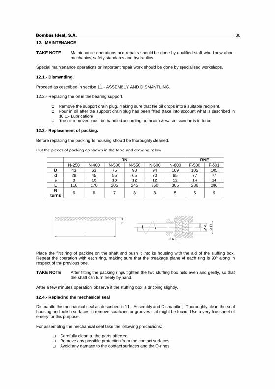
12.3.- Replacement of packing. Before replacing the packing its housing should be thoroughly cleaned. Cut the pieces of packing as shown in the table and drawing below.
RN RNE N-250 N-400 N-500 N-550 N-600 N-800 F-500 F-501
D 43 63 75 90 94 109 105 105 d 28 45 55 65 70 85 77 77 s 8 10 10 12 12 12 14 14 L 110 170 205 245 260 305 286 286 N
turns 6 6 7 8 8 5 5 5
Place the first ring of packing on the shaft and push it into its housing with the aid of the stuffing box. Repeat the operation with each ring, making sure that the breakage plane of each ring is 90º along in respect of the previous one. TAKE NOTE After fitting the packing rings tighten the two stuffing box nuts even and gently, so that
the shaft can turn freely by hand. After a few minutes operation, observe if the stuffing box is dripping slightly. 12.4.- Replacing the mechanical seal Dismantle the mechanical seal as described in 11.- Assembly and Dismantling. Thoroughly clean the seal housing and polish surfaces to remove scratches or grooves that might be found. Use a very fine sheet of emery for this purpose. For assembling the mechanical seal take the following precautions:
� Carefully clean all the parts affected. � Remove any possible protection from the contact surfaces.
S
Ø D
Ø d
L
S
� Avoid any damage to the contact surfaces and the O-rings.
Bombas Ideal, S.A. 31
12.5.- Replacing the rubber flectors of the elastic coupling. The following sequence should be followed to replace the rubber flectors; 1. Remove the protection. 2. Dismantle the motor from the base plate as described in 11.- Assembly and dismantling. 3. Move the motor backwards until the two coupling halves become disengaged. 4. Change the worn rubber flectors. 5. Put the assembly together again taking into account the points stated in 8.3.- Aligning the Set, and
check this alignment after a short period of time.
Do not start the set without having fitted all the guards for the moving parts, to guarantee the safety requirements.
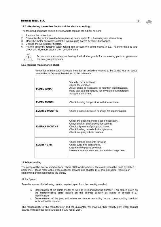
12.6-Routine maintenance chart
Preventive maintenance schedule includes all periodical checks to be carried out to reduce possibilities of failure or breakdown to the minimum.
EVERY WEEK
Visually check for leaks Check for vibration. Adjust gland as necessary to maintain slight leakage. Hand test bearing housing for any sign of temperature. Voltage and current.
EVERY MONTH
Check bearing temperature with thermometer.
EVERY 3 MONTHS
Check grease lubricated bearings for saponification.
EVERY 6 MONTHS
Check the packing and replace if necessary. Check shaft or shaft sleeve for scoring. Check alignment of pump and motor. Check holding down bolts for tightness. Check coupling rubber bushes.
EVERY YEAR
Check rotating elements for wear. Check wear ring clearances. Clean and regrease bearings. Measure total dynamic suction and discharge head.
12.7-Overhauling The pump will be due for overhaul after about 5000 working hours. This work should be done by skilled personnel. Please refer to the cross sectional drawing and chapter 11 of this manual for learning on dismantling and reassembling the pump.
12.8.- Spares. To order spares, the following data is required apart from the quantity needed:
� Identification of the pump model as well as its manufacturing number. This data is given on the characteristics plate located on the bearing support as stated in section 3 3.- Identification.
� Denomination of the part and reference number according to the corresponding sections included in this manual.
The responsibility of the manufacturer and the guarantee will maintain their validity only when original spares from Bombas Ideal are used in any repair work.
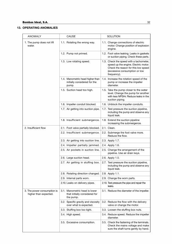
OPERATING ANOMALIES
Bombas Ideal, S.A. 32
13.
ANOMALY CAUSE SOLUTION
1.1. Rotating the wrong way.
1.2. Pump not primed.
1.3. Low rotating speed.
1.4. Manometric head higher than
initially considered for the
pump.
1.5. Suction head too high.
1.6. Impeller conduit blocked.
1.7. Air getting into suction pipe.
1.8. Insufficient submergence.
1. The pump does not lift
water.
2.1. Foot valve partially blocked.
2.2. Insufficient submergence.
2.3. Air getting into suction line.
2.4. Impeller partially jammed.
2.5. Air pockets in suction line.
2.6. Large suction head.
2.7. Air getting in stuffing box.
2.8. Rotating direction changed.
2.9. Internal parts worn.
2.10. Leaks on delivery pipes.
3.1. Manometric head is lower
that initially considered for
the pump.
3.2. Specific gravity and viscosity
over what is expected.
3.3. Stuffing box too tight.
3.4. High speed.
3.5. Excessive consumption.
1.1. Change connections of electric
motor. Change position of explosion
engine.
1.2. Foot valve leaking. Leaks in gaskets
or suction piping. Check these parts.
1.3. Check the speed with a tachometer,
speed up the engine. Electric motor.
Check the reason for this low speed
(excessive consumption or low
frequency).
1.4. Increase the rotation speed of the
pump or increase the impeller
diameter.
1.5. Take the pump closer to the water
level. Change the pump for another
with less NPSHr. Reduce leaks in the
suction piping.
1.6. Unblock the impeller conduits.
1.7. Test pressure the suction pipeline,
including the pump and observe any
liquid leak.
1.8. Extend the suction pipeline
increasing the submergence.
2.1. Clean.
2.2. Submerge the foot valve more.
Reduce the flow.
2.3. Apply 1.7.
2.4. Apply 1.6.
2.5. Change the arrangement of the
pipeline. Use air drain keys.
2.6. Apply 1.5.
2.7. Test pressure the suction pipeline,
including the pump and observe any
liquid leak.
2.8. Apply 1.1.
2.9. Change the worn parts.
2.10. Test pressure the pipe and repair the
leaks.
3.1. Reduce the diameter of the impeller.
3.2. Reduce the flow with the delivery
valve or change the motor.
3.3. Loosen the stuffing box nuts.
3.4. Reduce speed. Reduce the impeller
diameter.
3.5. Check the fastening of the terminals.
Check the mains voltage and make
sure the shaft turns gently by hand.
2. Insufficient flow
3. The power consumption is
higher than expected.
Bombas Ideal, S.A. 33
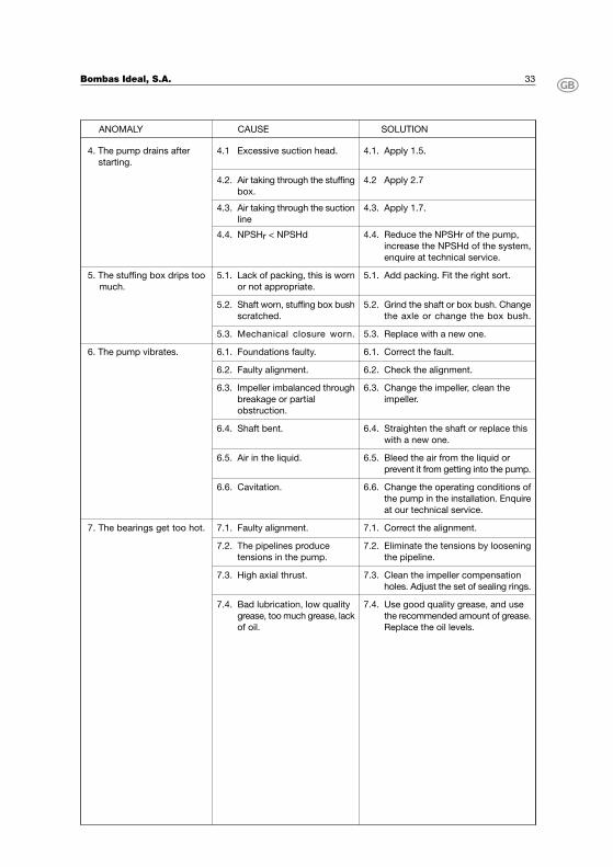
ANOMALY CAUSE SOLUTION
4.1 Excessive suction head.
4.2. Air taking through the stuffing
box.
4.3. Air taking through the suction
line
4.4. NPSHr < NPSHd
5.1. Lack of packing, this is worn
or not appropriate.
5.2. Shaft worn, stuffing box bush
scratched.
5.3. Mechanical closure worn.
4. The pump drains after
starting.
6.1. Foundations faulty.
6.2. Faulty alignment.
6.3. Impeller imbalanced through
breakage or partial
obstruction.
6.4. Shaft bent.
6.5. Air in the liquid.
6.6. Cavitation.
7.1. Faulty alignment.
7.2. The pipelines produce
tensions in the pump.
7.3. High axial thrust.
7.4. Bad lubrication, low quality
grease, too much grease, lack
of oil.
7. The bearings get too hot.
5. The stuffing box drips too
much.
6. The pump vibrates.
4.1. Apply 1.5.
4.2 Apply 2.7
4.3. Apply 1.7.
4.4. Reduce the NPSHr of the pump,
increase the NPSHd of the system,
enquire at technical service.
5.1. Add packing. Fit the right sort.
5.2. Grind the shaft or box bush. Change
the axle or change the box bush.
5.3. Replace with a new one.
6.1. Correct the fault.
6.2. Check the alignment.
6.3. Change the impeller, clean the
impeller.
6.4. Straighten the shaft or replace this
with a new one.
6.5. Bleed the air from the liquid or
prevent it from getting into the pump.
6.6. Change the operating conditions of
the pump in the installation. Enquire
at our technical service.
7.1. Correct the alignment.
7.2. Eliminate the tensions by loosening
the pipeline.
7.3. Clean the impeller compensation
holes. Adjust the set of sealing rings.
7.4. Use good quality grease, and use
the recommended amount of grease.
Replace the oil levels.

NOTAS / NOTES
Bombas Ideal, S.A.
Index
Introduction 36
Description et utilisation 37
Identification 37
Garantie 38
Réception de la forniture 38
Emmagasinage 38
Manipulation 38
Montage et installation 39
Fonctionnement, mise en marche et arrêt 43
Contrôles 43
Montage et démontage 45
Entretien 46
Anomalies de fonctionnement 48
Annexes 51
INTRODUCTION
Ce manuel technique s'adresse aux usagers de pompes horizontales types RN et RNI. Il contient les instructions
d'installation, de fonctionnement et d'entretien.
Avant toute intervention sur l'équipement, l'usager doit lire attentivement ce manuel et suivre tous les conseils
et recommandations qu'il contient, en particulier celles précédées des symboles de sécurité suivantes:
Le non-respect de ces instructions peut entraîner des risques importants pour l'intégrité
des personnes.
Le non-respect de ces instructions peut entraîner des risques de danger électrique pour
les personnes.
ATTENTION Les instructions apparaissant après ce message indiquent qu'elles sont importantes pour
l'installation, l'utilisation et l'entretien adéquats de l'équipement.
Les instructions contenues dans ce manuel remplissent la Directive de la CEE sur Machines nº89/399, ainsi
que ses modifications ultérieures.
Dans le but d'améliorer les performances de ses produits, Bombas Ideal S.A. se réserve le droit de modifier
le contenu du présent manuel et/ou le produit lui-même, et cela sans avoir à en aviser préalablement les clients.
Le non-respect des conseils et recommandations contenues dans ce manuel, de même qu’une mauvaise
utilisation ou la manipulation non autorisée du produit, dégage automatiquement Bombas Ideal S.A. de toute
responsabilité face aux possibles dommages causés, qu'ils soient matériels ou personnels.
Pour tout doute ou information concernant ce produit, son utilisation, son entretien ou sa réparation veuillez
contacter:
Bombas Ideal S.A.
Polig. Ind. Mediterráneo C/Cid nº 8
Tél. +34 961 402 143 Fax +34 961 402 131
46560 Massalfassar – Valence – Espagne
Nos pompes sont livrées avec le manuel et celui ci doit toujours rester à proximité du lieu d'installation, dûment
protégé afin de pouvoir être consulté à tout moment par les usagers en cas de besoin.
Bombas Ideal, S.A. 36
1.
Bombas Ideal, S.A. 37
DESCRIPTION ET UTILISATION
Description
Les dimensions et caractéristiques hydrauliques des pompes RN et RNI, remplissent les conditions de la norme
DIN 24255 et annexes.
Les pompes RN et RNI sont des pompes centrifuges horizontales à rotor unique, aspiration axiale et refoulement
vertical en hauteur, avec pattes de fixation dans la volute (ou colimaçon) qui est ouverte du côté couplage ce
qui permet de démonter les parties tournantes sans avoir à déplacer les tuyauteries d'aspiration et de refoulement
de l'installation, à l'exception des modèles RN-PF où il faut démonter le corps d'aspiration pour avoir accès
au rotor.
Le rotor ou impulseur est du type fermé. Le sens de rotation est horaire (vers la droite) et situé du côté couplage.
Le carter de presse-étoupe logé dans le couvercle corps est prévu pour recevoir un presse étoupe à tresses
d'une qualité adéquate au liquide pompé, ainsi que pour monter une garniture mécanique avec des dimensions
selon la norme DIN 24960.
L'arbre d'entraînement est supporté par deux roulements rigides à billes, lubrifiés à la graisse ou à l'huile.
Elles peuvent être entraînées par moteur thermique ou électrique sur banc commun et unies par un accouplement
semi-élastique.
Utilisation.
Les pompes RN et RNI son adaptées pour élévation et dépotage de liquides dans les industries, es installations
d'irrigation, mines, la construction, l'approvisionnement urbain, installations d'air conditionné, équipements
incendies, etc.
Dans leur version standard, elles ont été conçues pour le dépotage d'eau propre jusqu'à une température
maximum de 100º C.
Les pompes sont aussi disponibles sur commande avec configurations spéciales capables de pomper différents
types de liquides et à des températures allant jusqu'à 160º C.maximum.
Avertissement:
� Les pompes ne doivent jamais être installées dans locaux où il y a risque d'explosion.� Les pompes ne doivent jamais être utilisées pour le dépotage de liquides inflammables.
IDENTIFICATION
Les pompes RN et RNI possèdent une plaque métallique sur le support de roulements où figurent les indications
suivantes:
TYPE : identification du modèle de pompe.
Nº: numéro de fabrication.
Si au moment du contrat d'achat ou de la commande il est requis un point de travail déterminé, débit et hauteur,
les mentions suivantes devront figurer sur la plaque :
Q (m3 / h) : débit en mètres cubes par heure.
H (m) : hauteur manométrique en mètres.
2.2.
2.
2.1.
3.
GARANTIE
Suivant les termes figurant dans ses conditions générales de vente, Bombas Ideal S.A., garantit les pompes
contre tous les défauts de matériels et de fabrication pour une période de 12 mois à compter de la date de
livraison.
Le non-respect des conseils et recommandations contenues dans ce manuel ainsi que la mauvaise utilisation
ou la manipulation non autorisée du produit invalide totalement la garantie.
La garantie exclut l'usure pour utilisation, l'utilisation incorrecte et la réparation ou le remplacement des pièces
défectueuses par l'usager lui-même ou par du personnel non qualifié sans l'autorisation expresse de Bombas
Ideal S.A.
RÉCEPTION DE LA FOURNITURE
A la réception de la fourniture, il y a lieu de vérifier que:
� L'emballage n'a pas subi de dommages pendant le transport. Dans le cas contraire, adresser la
réclamation correspondante au transporteur.� Le matériel livré correspond bien aux spécifications de la commande.� Le matériel n'a subi aucun dommage pendant le transport.� Le Manuel technique est livré avec le matériel.
ATTENTION Toute anomalie détectée doit être communiquée immédiatement à Bombas Ideal S.A.
EMMAGASINAGE
Les pompes seront emmagasinées dans des zones aérées et non humides.
Pour les courtes périodes d'emmagasinage, les parties usinées seront protégées avec de l'huile ou tout autre
produit anticorrosif.
Si la durée de stockage doit se prolonger, il faudra prendre toutes les mesures nécessaires en vue d'éviter la
corrosion de la pompe, en particulier l'usage d'un produit anticorrosif et la fermeture des orifices d'aspiration
et de refoulement. Tous les 15 jours, il faudra tourner manuellement l'arbre pour éviter des éventuels grippements.
ATTENTION S'assurer que le moteur thermique ou électrique n'est pas exposé aux agents atmosphériques
non compatibles avec son degré de protection et pouvant l'endommager.
Avant d'emmagasiner une pompe récemment installée, il faut la nettoyer (sans utiliser de produits dérivés
d'hydrocarbures) et la sécher au jet d'air.
MANIPULATION
Pour la manipulation des équipements il faut utiliser des systèmes de levage et de transport
adaptés et conformes aux normes de sécurité.
Les pompes en version arbre nu libre doivent être manipulées en utilisant comme point de levage la bride de
refoulement, pour la positionner au besoin utiliser la bride d'aspiration et le support de l'arbre. Les modèles
RNI disposent d'un œillet pour le levage.
Le moteur électrique doit être manipulé en utilisant le ou les points de fixation prévus à cet effet, généralement
un anneau situé dans la partie supérieure de la carcasse (pour moteurs avec pattes).
Bombas Ideal, S.A. 38
4.
5.
6.
7.
Bombas Ideal, S.A. 39
Pour les moteurs thermiques, consulter le manuel du moteur.
Pour manipuler l'ensemble pompe moteur utiliser une élingue passant par la base du banc de manière à assurer
la stabilité pendant le levage et le déplacement. Ne jamais utiliser l'anneau situé sur le moteur ou la pompe.
MONTAGE ET INSTALLATION8.
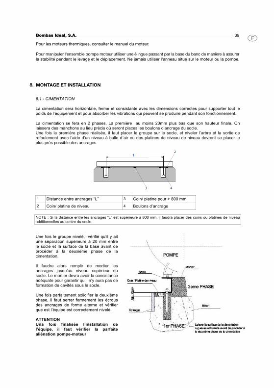
8.1.- CIMENTATION La cimentation sera horizontale, ferme et consistante avec les dimensions correctes pour supporter tout le poids de l’équipement et pour absorber les vibrations qui peuvent se produire pendant son fonctionnement. La cimentation se fera en 2 phases. La première au moins 20mm plus bas que son hauteur finale. On laissera des manchons au lieu précis où seront places les boulons d’ancrage du socle. Une fois la première phase réalisée, il faut placer le groupe sur le socle, et niveler l’arbre et la sortie de refoulement avec l’aide d’un niveau à bulle d´air ou des platines de niveau de niveau devront se placer le plus près possible des ancrages.
1 Distance entre ancrages “L” 3 Coin/ platine pour > 800 mm 2 Coin/ platine de niveau 4 Boulons d’ancrage NOTE : Si la distance entre les ancrages “L” est supérieure à 800 mm, il faudra placer des coins ou platines de niveau additionnelles au centre du socle. Une fois le groupe nivelé, vérifié qu’il y ait une séparation supérieure à 20 mm entre le socle et la surface de la base avant de procéder à la deuxième phase de la cimentation. Il faudra alors remplir de mortier les ancrages jusqu’au niveau supérieur du socle. Le mortier devra avoir la consistance adéquate pour garantir qu’il n’y aura pas de formation de cavités sous le socle. Une fois parfaitement solidifier la deuxième phase, il faut serrer fermement les écrous des ancrages de forme alterne et vérifier que est l’équipe est correctement nivelé. ATTENTION Una fois finalisée l’installation de l’équipe, il faut vérifier la parfaite aliénation pompe-moteur
Bombas Ideal, S.A. 40
1. Clapet de pied avec crépine.2. Coude au grand rayon.3. Tuyauterie ascendante.
Inclinaison minimum 2%4. Cône excentrique.5. Bouchon de purge.6. Soupape de retenue.7. Vanne de réglage.8. Manchon avec écarteur.9
.
Tuyauterie de refoulement.
TAKE CARE the pipes should be held on supports close to the pump body so that they do not transmit any stresses on the pump flanges. Pump and pipe flanges must face each other perfectly. It’s also recommended to use rubber expansion joints to reduce stress and isolate vibration both on suction and discharge branches.
Installation Hydraulique
Le lieu d'emplacement de la pompe sera le plus près possible du niveau du liquide, ceci dans le but d'éviter
des tuyauteries d'aspiration trop longues. Sa position répondra au critère voulant que le NPSHd doit toujours
être supérieur au NPSHr de la pompe.
Pour le bon fonctionnement de la pompe, le tracé et les dimensions de la tuyauterie d'aspiration doivent remplir
les conditions suivantes:
1. La tuyauterie d'aspiration doit être courte, avec le moins de coudes possibles et ceux-ci devant avoir
un grand rayon de courbature. Le dernier segment avant la pompe doit être droit.
2. Le diamètre doit être 1,5 à 2 fois le pas de la bride d'aspiration de la pompe.
3. Le cône d'entrée doit être excentrique lorsque la pompe travaille en dépression. Si elle travaille en
charge, ce cône peut être concentrique.
4. La tuyauterie sera ascendante vers la pompe, avec une inclinaison de 2% minimum.
5. Elle sera hermétique à l'entrée d'air.
6. Pour amorcer la pompe lorsque celle-ci travaille en dépression, il faut disposer d'un clapet de pied
adéquat et placé à la profondeur nécessaire (submergence) afin d'éviter la prise d'air par la formation
de tourbillons.
La tuyauterie de refoulement doit remplir les conditions suivantes:
1. Être hermétique.
2. Avoir des dimensions adéquates pour ne pas causer de pertes de charge excessives.
3. Disposer d'une vanne de réglage à la sortie de la pompe.
4. Au besoin, il faut installer un clapet de retenue entre la pompe et la vanne de réglage ainsi que les
dispositifs adéquats pour éliminer les effets négatifs d'éventuels coups de bélier.
8.2.
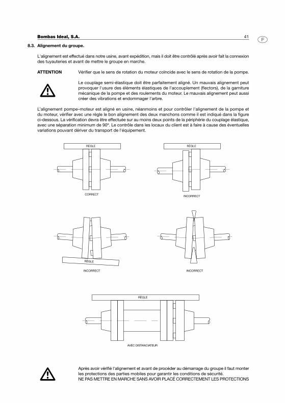
Bombas Ideal, S.A. 41
Alignement du groupe.
L'alignement est effectué dans notre usine, avant expédition, mais il doit être contrôlé après avoir fait la connexion
des tuyauteries et avant de mettre le groupe en marche.
ATTENTION Vérifier que le sens de rotation du moteur coïncide avec le sens de rotation de la pompe.
Le couplage semi-élastique doit être parfaitement aligné. Un mauvais alignement peut
provoquer l'usure des éléments élastiques de l’accouplement (flectors), de la garniture
mécanique de la pompe et des roulements du moteur. Le mauvais alignement peut aussi
créer des vibrations et endommager l'arbre.
L’alignement pompe–moteur est aligné en usine, néanmoins et pour contrôler l'alignement de la pompe et
du moteur, vérifier avec une règle le bon alignement des deux manchons comme il est indiqué dans la figure
ci-dessous. La vérification devra être effectuée sur au moins deux points de la périphérie du couplage élastique,
avec une séparation minimum de 90º. Le contrôle dans les locaux du client est à faire à cause des éventuelles
variations pouvant dériver du transport de l'équipement.
Après avoir vérifié l'alignement et avant de procéder au démarrage du groupe il faut monter
les protections des parties mobiles pour garantir les conditions de sécurité.
NE PAS METTRE EN MARCHE SANS AVOIR PLACÉ CORRECTEMENT LES PROTECTIONS
8.3.
RÈGLE
CORRECT
RÈGLE
RÈGLE
RÈGLE
INCORRECT
INCORRECT INCORRECT
AVEC DISTANCIATEUR
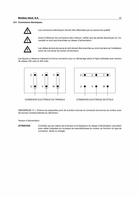
Connexions électriques.
Les connexions électriques doivent être effectuées par du personnel qualifié.
Avant d'effectuer les connexions des moteurs, vérifier que les parties électriques où l'on
travaille ne sont pas branchées au réseau d'alimentation.
Les câbles de terre (en jaune et vert) doivent être branchés au circuit de terre de l'installation
avant de connecter les autres conducteurs.
Les figures ci-dessous indiquent la bonne connexion pour un démarrage direct et ligne triphasée avec tension
de réseau 230 volts et 400 volts.
DÉMARRAGE Y/�. Enlever les plaquettes pont de la boîte à bornes et connecter les bornes du moteur avec
les bornes correspondantes du démarreur.
Tension d'alimentation
ATTENTION Contrôler que les valeurs de la tension et la fréquence du réseau d'alimentation coïncident
avec celles indiquées sur la plaque de caractéristiques du moteur, en fonction du type de
connexion, étoile ou triangle.
Bombas Ideal, S.A. 42
8.4.
Z
U
X
V
Y
W WVU
Z X Y
CONNEXION ÉLECTRIQUE EN TRIANGLE CONNEXION ÉLECTRIQUE EN ÉTOILE
Bombas Ideal, S.A. 43
FONCTIONNEMENT, MISE EN MARCHE ET ARRÊT
Le fonctionnement des pompes centrifuges du type RN et RNI est simple et sûr. Il est interdit d'utiliser une
pompe pour un fonctionnement autre que celui pour lequel elle a été proposée. Si les conditions de l'installation
de la pompe ont varié, le client est tenu de le communiquer à Bombas Ideal S.A. ou à ses services techniques
dans le but d’étudier les changements nécessaires pour l'adapter aux nouvelles conditions.
Mise en Marche.
Avant de mettre l'équipement en marche, suivre les indications suivantes:
1. Vérifier le bon amorçage de la pompe et de la tuyauterie, le fluide doit déborder l'installation pour
garantir que l'air a été purgé, en particulier celui contenu dans la tuyauterie d'aspiration.
2. La garniture doit être parfaitement placée et serrée en douceur.
3. Vérifier manuellement que l'arbre tourne facilement sans effort.
4. Vérifier l'alignement du groupe suivant la description faite au point 8.3.
5. Vérifier que le sens de rotation est le mème que celui indiqué par une flèche sur le corps de pompe.
6. Dans le cas de la lubrification par huile, vérifier le niveau de remplissage de la boîte de roulements.
7. Dans le cas de carters de presse-étoupe réfrigérés, on vérifiera que le liquide réfrigérant circule bien.
8. Vérifier que toutes les protections des parties mobiles sont bien montées.
Après avoir effectué toutes les vérifications opportunes, la première mise en marche doit être faite avec le clapet
de refoulement fermé, pour réduire au minimum la consommation de la pompe. Lorsque qu'on a atteint la
vitesse de régime, le clapet s'ouvre lentement et on observe en même temps la variation de la consommation
jusqu'à son ouverture totale. En régime normal, la consommation, mesurée en ampères ne doit pas dépasser
celle indiquée sur la signalétique du moteur.
Arrêt de la pompe
Pour procéder à l'arrêt de l'équipement, la vanne de réglage doit être mise sur la même position que celle
maintenue pendant la mise en marche. L'arrêt peut être effectué avec la vanne de réglage ouverte au cas où
l'installation serait pourvue d'un dispositif anti-bélier.
Contrôler que la décélération du moteur est normale et fermer les circuits auxiliaires après l'arrêt.
Lors de périodes d'arrêt prolongées des équipements, purger entièrement la pompe et les tuyauteries afin
d'éviter les risques de gel pendant l'hiver et la possible oxydation des éléments mécaniques à cause du liquide
restant.
CONTRÔLES
Le fonctionnement des pompes centrifuges est simple et sûr et n'a pas besoin d'être contrôlé exhaustivement,
néanmoins et pour garantir leur fonctionnement correct, il est important de suivre les indications suivantes, dès
le premier démarrage et après une période prolongée de fonctionnement:
1. Le fonctionnement doit être silencieux et ne pas provoquer de vibrations. Après les premières 200
heures d'utilisation, contrôler le bon alignement de l'équipement pompe–moteur comme il est décrit
au point 8.3.- Alignement du groupe.
2. Vérifier que le débit et la pression de fonctionnement correspondent avec ceux déterminés dans les
champs de travail (voir la documentation technique correspondante de Bombas Ideal S.A.).
3. Pour les équipements avec moteur électrique, contrôler que la puissance absorbée (consommation
en ampères) ne dépasse pas les valeurs indiquées sur la plaque signalétique du moteur.
4. La chaleur produite par le frottement de la garniture avec l'arbre (dans le cas de pompes fournies
avec garniture) est éliminée par réfrigération avec le liquide pompé lui-même, c'est pourquoi il faut
assurer un égouttement léger. Si l'égouttement est trop fort et on ne peut pas le réduire en serrant
le presse-étoupe, il faudra remplacer l'étoupe (voir point Entretien).
9.
9.1.
9.2.
10.
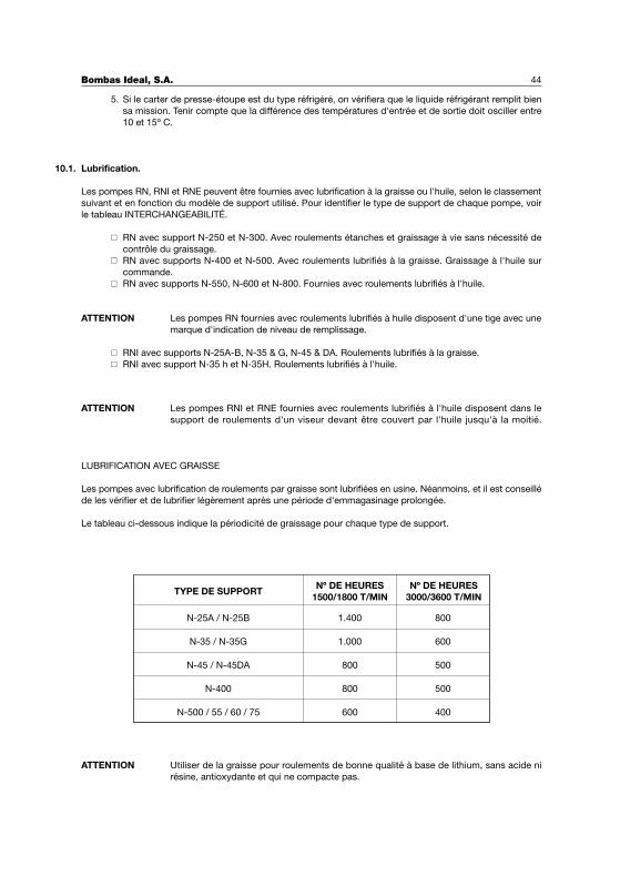
5. Si le carter de presse-étoupe est du type réfrigéré, on vérifiera que le liquide réfrigérant remplit bien
sa mission. Tenir compte que la différence des températures d'entrée et de sortie doit osciller entre
10 et 15º C.
Lubrification.
Les pompes RN, RNI et RNE peuvent être fournies avec lubrification à la graisse ou l'huile, selon le classement
suivant et en fonction du modèle de support utilisé. Pour identifier le type de support de chaque pompe, voir
le tableau INTERCHANGEABILITÉ.
� RN avec support N-250 et N-300. Avec roulements étanches et graissage à vie sans nécessité de
contrôle du graissage.� RN avec supports N-400 et N-500. Avec roulements lubrifiés à la graisse. Graissage à l'huile sur
commande.� RN avec supports N-550, N-600 et N-800. Fournies avec roulements lubrifiés à l'huile.
ATTENTION Les pompes RN fournies avec roulements lubrifiés à huile disposent d'une tige avec une
marque d'indication de niveau de remplissage.
� RNI avec supports N-25A-B, N-35 & G, N-45 & DA. Roulements lubrifiés à la graisse.� RNI avec support N-35 h et N-35H. Roulements lubrifiés à l'huile.
ATTENTION Les pompes RNI et RNE fournies avec roulements lubrifiés à l'huile disposent dans le
support de roulements d'un viseur devant être couvert par l'huile jusqu'à la moitié.
LUBRIFICATION AVEC GRAISSE
Les pompes avec lubrification de roulements par graisse sont lubrifiées en usine. Néanmoins, et il est conseillé
de les vérifier et de lubrifier légèrement après une période d'emmagasinage prolongée.
Le tableau ci-dessous indique la périodicité de graissage pour chaque type de support.
ATTENTION Utiliser de la graisse pour roulements de bonne qualité à base de lithium, sans acide ni
résine, antioxydante et qui ne compacte pas.
Bombas Ideal, S.A. 44
10.1.
TYPE DE SUPPORTNº DE HEURES
1500/1800 T/MINNº DE HEURES
3000/3600 T/MIN
N-25A / N-25B
N-35 / N-35G
N-45 / N-45DA
N-400
N-500 / 55 / 60 / 75
1.400
1.000
800
800
600
800
600
500
500
400
Bombas Ideal, S.A. 45
LUBRIFICATION À L'HUILE
Lorsque la lubrification est à l'huile, il est conseillé vidanger celle-ci entièrement après les deux cents premières
heures de fonctionnement. Les vidanges suivantes peuvent être effectuées toutes les 1.000 heures ou au
minimum une fois par an, à condition que la température ambiante soit inférieure à 50º C. Pour des températures
ambiantes supérieures à 50º C, raccourcir la fréquence de vidange d'huile.
ATTENTION Utiliser des huiles avec une viscosité 4 à 6 ENGLER à 40º C
MONTAGE ET DÉMONTAGE.
Au cas où il serait nécessaire de démonter la pompe pour effectuer une opération d'entretien ou de réparation,
suivre le procédé suivant:
Le nom de chaque pièce est suivi de son numéro de référence, aussi bien dans les sections de ce manuel que
dans la nomenclature des pièces.
Généralement le corps de pompe nº 379 ne requiert aucune intervention, et donc il restera uni aux tuyauteries
d'aspiration et de refoulement. En premier lieu, il faut vider le liquide contenu dans les tuyauteries et dans le
corps de la pompe en desserrant le bouchon vidange pompe nº 42. On effectue aussi la vidange de l'huile,
dans le cas des pompes lubrifiées à l'huile, en desserrant le bouchon vidange support nº 41 du support
roulements nº 789.
On peut alors démonter le moteur du banc et accéder au démontage des parties tournantes de la pompe. Si
láccouplement élastique est avec pièce d’espacement, il sufflit de démonter celui-ci.
Enlever les vis nº 51 (sur les RN supports N-250, N-400 et N-500) fixant le couvercle du corps nº 812 au corps
de pompe nº379. Pour les modèles RNI, il faut enlever les écrous nº 96. Ainsi on démonte l'ensemble formé
par le support roulements nº 789, le couvercle corps nº 812 et le rotor nº 726.
Pour séparer le rotor nº 726 de l'ensemble, Pour les modèles RN, desserrer le prisonnier et l'écrou fixation rotor
nº 828. Pour les modèles RNI desserrer l'écrou fixation rotor nº 828 et enlever la rondelle butée rotor nº 236.
La clavette réglage rotor nº 22 doit être gardée en lieu sûr afin d'éviter les coups et l'oxydation.
Enlever les vis nº 33 (Pour les modèles RN) ou les écrous nº 95 (Pour les modèles RNI) qui fixent le support
roulements nº 789 au couvercle corps nº 812 pour démonter la garniture mécanique nº 63. Pour les modèles
RN avec garniture, on démonte le presse-étoupe nº 653 la garniture nº 32 et le couvercle corps nº 812.
Enlever les vis nº 34 des deux couvercles roulement nº 810 et 811, démonter ceux-ci et séparer l'arbre nº450
avec les roulements nº 29 et 30 de leur logement dans le support roulements nº 789. Utiliser les procédés
habituels pour séparer les roulements de l'arbre.
Toutes les pièces seront manipulées avec soin, en les graissant et les gardant dans un endroit adéquat jusqu'à
leur remontage. Pour le nettoyage des roulements et leurs logements, utiliser de l'essence, du benzol ou un
produit avec des caractéristiques similaires.
Après avoir réparé ou changé les pièces défectueuses, procéder au montage de la pompe en suivant le procédé
inverse à celui décrit ci-dessus.
11.
(ISO VG68, SAE20, SAE10W 30)
AGIP Acer 68SHELL Tellos 68ESSO Nuto 68
MOBIL DTE 26TEXACO Rando HD 68
LUBRIFICATION RECOMMANDÉE:
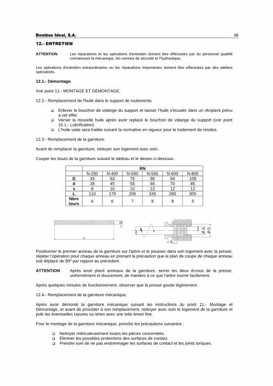
Bombas Ideal, S.A. 46
12.- ENTRETIEN
ATTENTION Les réparations et les opérations d'entretien doivent être effectuées par du personnel qualifiéconnaissant la mécanique, les normes de sécurité et l'hydraulique.
Les opérations d'entretien extraordinaires ou les réparations importantes doivent être effectuées par des ateliersspécialisés.
12.1.- Démontage .
Voir point 11.- MONTAGE ET DÉMONTAGE.
12.2.- Remplacement de l'huile dans le support de roulements.
� Enlever le bouchon de vidange du support et laisser l'huile s'écouler dans un récipient prévuà cet effet.
� Verser la nouvelle huile après avoir replacé le bouchon de vidange du support (voir point10.1.- Lubrification)
� L'huile usée sera traitée suivant la normative en vigueur pour le traitement de résidus.
12.3.- Remplacement de la garniture.
Avant de remplacer la garniture, nettoyer son logement avec soin.
Couper les bouts de la garniture suivant le tableau et le dessin ci-dessous.
RNN-250 N-400 N-500 N-550 N-600 N-800
D 43 63 75 90 94 109d 28 45 55 65 70 85s 8 10 10 12 12 12L 110 170 205 245 260 305
Nbretours 6 6 7 8 8 5
Positionner le premier anneau de la garniture sur l'arbre et le pousser dans son logement avec la presse,répéter l'opération pour chaque anneau en prenant la précaution que le plan de coupe de chaque anneausoit déplacé de 90º par rapport au précédent.
ATTENTION Après avoir placé anneaux de la garniture, serrer les deux écrous de la presse,uniformément et doucement, de manière à ce que l'arbre tourne facilement.
Après quelques minutes de fonctionnement, observer que la presse goutte légèrement.
12.4.- Remplacement de la garniture mécanique.
Après avoir démonté la garniture mécanique suivant les instructions du point 11.- Montage etDémontage, et avant de procéder à son remplacement, nettoyer avec soin le logement de la garniture etpolir les éventuelles rayures ou stries avec une toile émeri fine.
Pour le montage de la garniture mécanique, prendre les précautions suivantes :
� Nettoyer méticuleusement toutes les pièces concernées.� Eliminer les possibles protections des surfaces de contact.
S
Ø D
Ø d
L
S
� Prendre soin de ne pas endommager les surfaces de contact et les joints toriques.
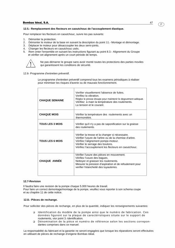
Bombas Ideal, S.A. 47 12.5.- Remplacement des flecteurs en caoutchouc de l'accouplement élastique. Pour remplacer les flecteurs en caoutchouc, suivre les pas suivants: 1. Démonter la protection. 2. Démonter le moteur de la base en suivant la description du point 11.- Montage et démontage.3. Déplacer le moteur pour désaccoupler les deux semi-joints. 4. Changer les flecteurs en caoutchouc usés. 5. Rem onter l'ensemble en suivant les instructions figurant au point 8.3.- Alignement du Groupe
et vérifier cet alignement après un court période de temps.
Ne pas démarrer le groupe sans avoir monté toutes les protections des parties moviles qui garantissent les conditions de sécurité.
12.6- Programme d'entretien préventif. Le programme d'entretien préventif comprend tous les examens périodiques à réaliserpour minimiser les risques d'averie ou de mauvais fonctíonnement.
CHAQUE SEMAINE
Verifier visuellement l'absence de fuites.Verifiez la vibration.Réglez le presse étoupe pour maìntenir le degoutment adéquat.Vérifiez à main la température des roulements.La tension et le courant.
CHAQUE MOIS
Vérifier la température des roulements avec un thermomètre.
TOUS LES 3 MOIS
Vérifier qu'il n'y a pas de saponification sur la graisse des roulements.
TOUS LES 6 MOIS
Vérifier la tresse et la changer si nécessaire.Vérifier l'usure de l'arbre ou de la chemise d'arbre.Vérifiez l'alignement pompe-moteur. Vérifier le serrage des boulons. Vérifiez l'accouplement les flecteurs en caoutchouc.
CHAQUE ANNÉE
Vérifier l'usure des pièces en mouvement.Vérifiez l'usure des bagues.Nettoyer et graisser les roulements.Mesurer la pression d'aspiratíon et de refoulement pour verifier l'etancheité des tuyauteries.
12.7-Revision Il faudra faire une revision de la pompe chaque 5.000 heures de travail. Pour faire un correct demontage/montage de la pompe, veuillez vous reporter à son schema coupe et au chapitre 11 de cette notice.
12.8.- Pièces de rechange.
Pour solliciter des pièces de rechange, en plus de la quantité, indiquer les renseignements suivantes:
� Ident i f icat ion du modèle de la pompe ainsi que le numéro de fabr icat ion. Ces données f igurent sur la plaque de carectér ist iques si tuée sur le support de roulements, vior point 3.-Identification.
� Dénominat ion de la pièce et numéro de référence selon les sect ions correpon-dantes comprises dans ce manuel.
La responsabilité du fabricant et la garantie ne seront engagées que lorsque les réparations seront effectuées en utilisant de pièces de rechange d'origene Bombas Ideal.
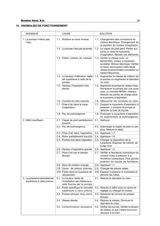
ANOMALIES DE FONCTIONNEMENT
Bombas Ideal, S.A. 48
13.
ANOMALIE CAUSE SOLUTION
1.1. Rotation en sens inverse.
1.2. La pompe n'est pas amorcée.
1.3. Faible vitesse de rotation.
1.4. La hauteur d'élévation réelle
est supérieure à celle de la
pompe.
1.5. Hauteur d'aspiration très
élevée.
1.6. Conduit du rotor bouché.
1.7. Prise d'air dans le tuyau
d'aspiration.
1.8. Peu de submergence.
1. La pompe n'élève pas
l'eau.
2.1. Clapet de pied partiellement
bouché.
2.2. Peu de submergence.
2.3. Prise d'air dans l'aspiration.
2.4. Rotor partiellement bouché.
2.5. Poches d'air dans l'aspiration.
2.6. Hauteur d'aspiration grande.
2.7. Prise d'air par le presse-
étoupe.
2.8. Sens de rotation changé.
2.9. Usure de pièces internes.
2.10. Fuites dans la tuyauterie de
refoulement.
3.1. La hauteur réelle de
l'installation est inférieure à
celle fournie par la pompe.
3.2. Poids spécifique et viscosité
supérieurs à ceux prévus.
3.3. Presse-étoupe trop serré.
3.4. Vitesse élevée
3.5. Consommation excessive.
1.1. Changement des connexions du
moteur électrique. Changement de
la position du moteur d'explosion.
1.2. Le clapet de pied perd. Pertes aux
joints ou dans la tuyauterie
d'aspiration. Réviser ces éléments.
1.3. Vérifier la vitesse avec un
tachymètre, moteur à explosion
accélérer. Moteur électrique. Vérifier
la raison provoquant cette faible
vitesse (consommation excessive ou
basse fréquence).
1.4. Augmenter la vitesse de rotation de
la pompe ou augmenter le diamètre
du rotor.
1.5. Approcher la pompe du niveau d'eau.
Remplacer la pompe par une autre
avec un moindre NPSHr. inferieur.
Réduire les pertes de charge dans
la tuyauterie d'aspiration.
1.6. Déboucher les conduits du rotor.
1.7. Essayer la tuyauterie d'aspiration à
pression, y compris la pompe et
détecter la fuite de liquide.
1.8. Prolonger la tuyauterie d'aspiration
en augmentant la submergence.
2.1. Nettoyer.
2.2. Submerger la clapet de pied un peu
plus. Réduire le débit.
2.3. Appliquer 1.7.
2.4. Appliquer 1.6.
2.5. Changer la disposition de la
tuyauterie. Disposer de robinet de
purge d'air.
2.6. Appliquer 1.5.
2.7. Vérifier la fermeture hydraulique du
conduit d'eau à pression à la
fermeture hydraulique. Plus grande
pression du liquide de fermeture.
2.8. Appliquer 1.1.
2.9. Changer les pièces usées.
2.10. Essayer à pression la tuyauterie et
éliminer les fuites.
3.1. Réduire le diamètre du rotor.
3.2. Réduire le débit avec la vanne de
réglage ou changer le moteur.
3.3. Desserrer les écrous du presse-
étoupe.
3.4. Réduire la vitesse. Diminuer le
diamètre du rotor.
3.5. Vérifier les bornes. Vérifier la tension
de réseau et que l'arbre tourne en
douceur à la main.
2. Débit insuffisant.
3. La puissance absorbée est
supérieure à celle prévue.
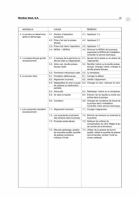
Bombas Ideal, S.A. 49
ANOMALIA CAUSA REMEDIO
4.1 Hauteur d'aspiration
excessive.
4.2. Prise d'air par le presse-
étoupe.
4.3. Prise d'air dans l'aspiration.
4.4. NPSHr < NPSHd
5.1. Il manque de la garniture ou
elle est usée ou inappropriée.
5.2. Arbre usé, douille presse-
étoupe rayée.
5.3. Fermeture mécanique usée.
4. La pompe se désamorce
après le démarrage.
6.1. Fondation défectueuse.
6.2. Alignement incorrect.
6.3. Déséquilibre du rotor à cause
de cassure ou obstruction
partielle.
6.4. Arbre plié.
6.5. Air dans le liquide.
6.6. Cavitation.
7.1. Alignement incorrect.
7.2. Les tuyauteries produisent
des tensions dans la pompe.
7.3. Poussée axiale élevée.
7.4. Mauvais graissage, graisse
de mauvaise qualité, quantité
de graisse excessive,
manque d'huile.
7. Les coussinets chauffent
excessivement.
5. Le presse-étoupe goutte
excessivement.
6. La pompe vibre.
4.1. Appliquer 1.5.
4.2 Appliquer 2.7.
4.3. Appliquer 1.7.
4.4. Diminuer le NPSHr de la pompe,
augmenter le NPSHd de l'installation,
consulter le service technique.
5.1. Ajouter de la tresse ou en placer de
l'appropriée.
5.2. Rectifier l'arbre ou la douille presse-
étoupe. Changer l'arbre, changer la
douille presse-étoupe.
5.3. La remplacer.
6.1. Corriger le défaut.
6.2. Vérifier l'alignement.
6.3. Changer le rotor, nettoyer le rotor.
6.4. Redresser l'arbre ou le remplacer.
6.5. Enlever l'air du liquide ou éviter son
entrée dans la pompe.
6.6. Changer les conditions de travail de
la pompe dans l'installation.
Consulter notre service technique.
7.1. Corriger l'alignement.
7.2. Eliminer les tensions en enlevant la
tuyauterie.
7.3. Nettoyer les orifices de
compensation du rotor. Régler le jeu
de cercles de la fermeture.
7.4. Utiliser de la graisse de bonne
qualité, utiliser la quantité de graisse
recommandée, remplir l'huile au
niveau adéquat.

NOTAS / NOTES
Bombas Ideal, S.A. 51
ANEXOS / ANNEXES / ANNEXS
Intercambiabilidad / Datos técnicos 52
Interchangeable / Dones techniques
Interchangeability / Technical data
Dimensiones 53
Dimensions
Dimensions
Dimensiones con bancada y motor 55
Dimensions avec socle et moteur
Dimensions with bed plate and motor
Corte 65
Coupe
Section
Denominación piezas 67
Denomination pieces
Name of parts
Materiales de construcción 68
Materiaux de construction
Materials of construction
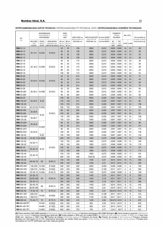
52
INTERCAMBIABILIDAD-DATOS TECNICOS / INTERCHANGEABILITY-TECHNICAL DATA / INTERCHANGEABLE-DONNÉES TECHNIQUES
(1) Cierre mecánico DIN 24960 estandar • Mechanical seat to DIN 24960 Standard • Gamiture mechanique DIN 24960 Standard. (2) Cierre mecánico opcional • Mechanicalseal under request • Gamiture mechanique optionnel. (3) Puede trabajar a 1800 rpm con rodete Ø380 • At 1800 rpm with maximun impeller of Ø380 mm • Avec roueØ380 mm. maximun a 1800 T/pm. Pt Presión de trabajo • Working pressure • Pression de travail. Pp Presión de prueba • Test pressure • Pression d’essaisBombas con terminación en H o PF, rodamientos lubricados por aceite. Resto por grasa / Pump ending in H or PF are oil lubricated, rest by grease / Pompes avecterminaison en H et PF lubrification par huile, reste par graisse.
INTERCAMBIABILIDADINTERCHANGEABILITYINTERCHANGEABLE
TIPOTYPE
BRIDASFLANGES
BRIDE RODETE Ø MAX. mm.IMPELLER Ø MAX. mm.
ROUE Ø MAX. mm.
LIMITE VELOCIDAD RPMSPEED LIMIT RPM
VITESSE MAX. T/pm
N/n directo KW/RPMN/n direct KW/RPMN/n direct KW/RPM
RODAMIENTOSBEARINGS
ROULEMENTSMAX. (105ºC)
Peso neto ejelibre KgNet weight frre shaft KgPoids net arbre nu Kg
N-25A65 50 6305 6305
RNI 32-16
RNI 40-16
RNI 50-16
RNI 65-16
RNI 80-16
RNI 32-26
RNI 40-26h
RNI 50-26h
RNI 80-20
RNI 100-20
RNI 125-20
RNI 150-20
RNI 65-32H
RNI 80-32H
RNI 100-32
RNI 150-26
RN 200-200
RN 250-250
RNI 200-32
RNI 250-32
RNI 200-40
RNI 250-40
RN 450-400 PF
RN 501-451 PF
RN 651-601 PF
139 3600 0,012 16 24
30
28
34
39
35
36
38
43
54
41
44
46
70
59
61
63
70
85
106
156
81
91
106
115
96
101
110
120
134
148
163
170
161
174
181
209
190
265
233
248
280
445
410
516
415
440
645
840
912
25-13-1 Ø 24(1)65 40 6305 6305139 3600 0,012 16 24
50 32 6305 6305139 3600 0,012 16 24
80 65 6305 6305139 3600 0,012 16 24
50 32 6305 6305174 3600 0,012 16 24
65 40 6305 6305175 3600 0,012 16 24
25-16-2 N-25B Ø 24(1) 65 50 6305 6305174 3600 0,012 16 24
80 65 6305 6305174 3600 0,012 16 24
100 80 6305 6305174 3600 0,012 16 24
50 32 6305 6305214 3600 0,012 16 24
25-20-3 N-25A Ø 24(1)65 40 6305 6305214 3600 0,012 16 24
65 50 6305 6305214 3600 0,012 16 24
80 65 6305 6305214 3000 0,012 16 24
50 32 6305 6305264 3000 0,012 16 24
25-26-4 Ø 24(1) 65 40 3305 6305264 3000 0,012 16 24
65 50 3305 6305264 3000 0,012 16 24
100 80 6307 6307214 3600 0,032 16 24
35-20-5 N-35 125 100 6307 6307214 3600 0,032 16 24
150 125 6307 6307214 3000 0,032 16 24
35-20-5G N-35G 200 150 6307 6307220 1800 0,032 16 21
80 65 3307 6307264 3000 0,032 16 2435-26-6
Ø 32(1) 100 80 3307 6307264 3000 0,032 16 24
35-26-7
N-35125 100 3307 3307264 3000 0,032 16 24
150 125 6307 6307264 1800 0,032 16 21
65 40 3307 3307320 3000 0,032 16 2435-32-9
N-35H65 50 3307 3307314 3000 0,032 16 24
80 65 3307 3307316 3000 0,032 16 24
35-32-8 100 80 3307 3307318 3000 0,032 16 24
N-35 125 100 6307 6307329 1800 0,032 16 21
45-26-13 N-45DA 200 150 6309 6309264 1800 0,072 10 16
45-32-11150 125 6309 6309329 1800 0,072 16 21
200 150 6309 6309329 1800 0,072 10 16
Ø 43(1) 100 80 6309 6309409 1800 0,072 13 1745-40-12 N-45
125 100 6309 6309409 1800 0,072 13 17
150 125 6309 6309409 1800 0,072 13 1745-40-10
200 150 6309 6309409 1500 (3) 0,072 10 16
150-250 N-400 Ø 45(2) 200 200 6409 6409230 3000 0,059 4 6
250 250 6411 6411290 2300 0,108 4 6
55-32-15 250 200 6311 6311340 1450 0,19 6 9
300 250 6311 6311328 1450 0,19 6 9
55-40-14 250 200 6311 6311418 1450 0,19 8 12
60-40-19 300 250 6312 6312422 1450 0,31 8 12
250 200 6312 6312500 1450 0,31 10 15
300 250 NU315 3315500 1450 0,31 10 15
N-500300 300 6411 6411328 2100 0,108 4 6
300 300 6411 6411345 1750 0,108 4 6
N-550 Ø 65(2) 450 400 6413 6413445 950 0,33 2 3
N-600 Ø 70(2) 500 450 6414 6414570 850 0,41 2 3
N-800 Ø 85(2) 650 600 22317 6317720 720 0,77 2 3
CIERRE MECANICOMECHANICAL SEAL
GAMITURE MECHANIQUE
TAPA CUERPOCOVER
COUVERCLE
SOPORTEBRACKETSUPPORT
ASP mm.SUC mm.ASP mm.
IMP mm.DISC mm.REF mm.
Pt BAR Pp BARANT.
FRONTAVANT
POST.BACK
ARRIERE
RNI 50-13
RNI 65-13
RNI 40-13
RNI 32-13
RNI 32-20
RNI 40-20
RNI 50-20
RNI 65-20
RNI 65-26h
RNI 80-26h
RNI 100-26H
RNI 125-26
RNI 40-32H
RNI 50-32H
RNI 125-32
RNI 150-32
RNI 80-40
RNI 100-40
RNI 125-40
RNI 150-40
RNI 200-50
RNI 250-50
RN 301-305
RN 300-315
N-25B
200-315 N-500 Ø 55(2)
RNI 200-26 45-26-13 N-45A Ø 43 (1) 190250 200 6309 6309264 1450 0,072 4 6
55-32-15G 55 Ø 55 (1)
60 Ø 60 (1)65-50-16G
75-50-18 75 Ø 75 (1)
200-315
300-315Ø 55(2)
RNI 300-40 75-40-17 75 Ø 75 (1) 350 300 NU315415 1450 0,62 6723315 6 9
RNI 125-50
RNI 150-50
300
30060-50-16
150 125 6312 6312500 1450 0,31 10 15
200 150 6312 6312500 1450 0,31 10 1560 Ø 60 (1)
Bombas Ideal, S.A.
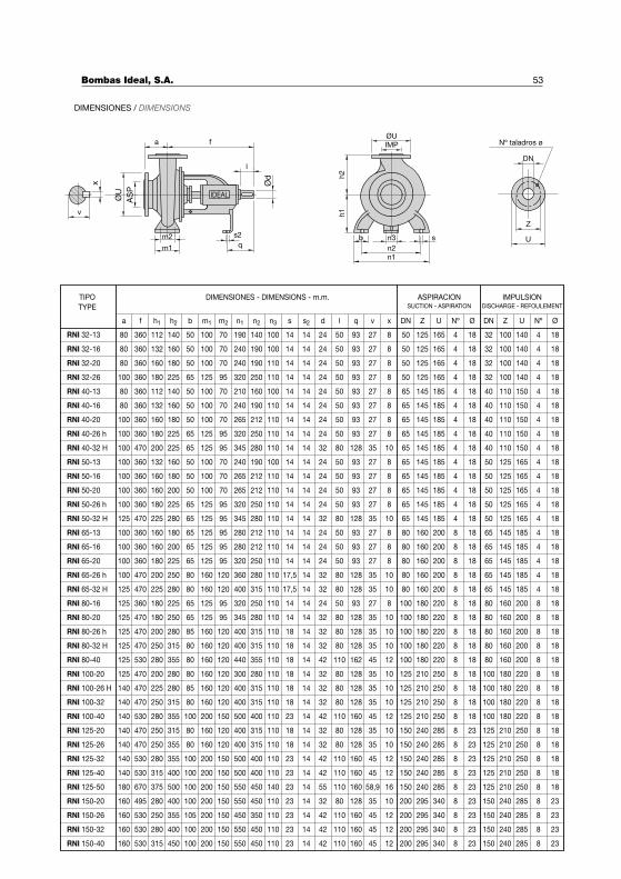
53
11236080
Nº ØUZDNØNºUZDNxvqlds2sn3n2n1m2m1bh2h1fa
13236080
16036080
180360100
11236080
13236080
160360100
180360100
200470100
132360100
160360100
160360100
180360100
225470125
160360100
160360100
180360100
200470100
225470125
180360125
180470125
200470125
250470125
280530125
200470125
225470140
250470140
280530140
250470140
250470140
280530140
315530140
375670180
280495160
250530160
280530160
315530160
RNI 32-16
RNI 32-20
RNI 32-26
RNI 40-13
RNI 40-16
RNI 40-20
RNI 40-26 h
RNI 40-32 H
RNI 50-13
RNI 50-16
RNI 50-20
RNI 50-26 h
RNI 50-32 H
RNI 65-13
RNI 65-16
RNI 65-20
RNI 65-26 h
RNI 65-32 H
RNI 80-16
RNI 80-20
RNI 80-26 h
RNI 80-32 H
RNI 80-40
RNI 100-20
RNI 100-26 H
RNI 100-32
RNI 100-40
RNI 125-20
RNI 125-26
RNI 125-32
RNI 125-40
RNI 125-50
RNI 150-20
RNI 150-26
RNI 150-32
RNI 150-40
IMPULSIONDISCHARGE - REFOULEMENT
ASPIRACIONSUCTION - ASPIRATION
DIMENSIONES - DIMENSIONS - m.m.TIPO
TYPE
DIMENSIONES / DIMENSIONS
n1n2
n3 sb
IMPØU
h2
h1
U
Z
DN
Nº taladros ø
x
v
IDEALØU
AS
P
m1
m2 s2
q
a f
l
Ød
140
160
180
225
140
160
180
225
225
160
180
200
225
280
180
200
225
250
280
225
250
280
315
355
280
280
315
355
315
355
355
400
400
355
400
450
50
50
50
65
50
50
50
65
65
50
50
50
65
65
65
65
65
80
80
65
65
85
80
80
80
85
80
100
80
80
100
100
100
105
100
100
100
100
100
125
100
100
100
125
125
100
100
100
125
125
125
125
125
160
160
125
125
160
160
160
160
160
160
200
160
160
200
200
200
200
200
200
70
70
70
95
70
70
70
95
95
70
70
70
95
95
95
95
95
120
120
95
95
120
120
120
120
120
120
150
120
120
150
150
150
150
150
150
190
240
240
320
210
240
265
320
345
240
265
265
320
345
280
280
320
360
400
320
345
400
400
440
300
400
400
500
400
400
500
500
550
450
550
550
140
190
190
250
160
190
212
250
280
190
212
212
250
280
212
212
250
280
315
250
280
315
315
355
280
315
315
400
315
315
400
400
450
350
450
450
100
100
110
110
100
110
110
110
110
100
110
110
110
110
110
110
110
110
110
110
110
110
110
110
110
110
110
110
110
110
110
110
110
110
110
110
14
14
14
14
14
14
14
14
14
14
14
14
14
14
14
14
14
17,5
17,5
14
14
18
18
18
18
18
18
23
18
18
23
23
23
23
23
23
14
14
14
14
14
14
14
14
14
14
14
14
14
14
14
14
14
14
14
14
14
14
14
14
14
14
14
14
14
14
14
14
14
14
14
14
24
24
24
24
24
24
24
24
32
24
24
24
24
32
24
24
24
32
32
24
32
32
32
42
32
32
32
42
32
32
42
42
32
42
42
42
50
50
50
50
50
50
50
50
80
50
50
50
50
80
50
50
50
80
80
50
80
80
80
110
80
80
80
110
80
80
110
110
80
110
110
110
27
27
27
27
27
27
27
27
35
27
27
27
27
35
27
27
27
35
35
27
35
35
35
45
35
35
35
45
35
35
45
45
35
45
45
45
8
8
8
8
8
8
8
8
10
8
8
8
8
10
8
8
8
10
10
8
10
10
10
12
10
10
10
12
10
10
12
12
10
12
12
12
50
50
50
50
65
65
65
65
65
65
65
65
65
65
80
80
80
80
80
100
100
100
100
100
125
125
125
125
150
150
150
150
200
200
200
200
125
125
125
125
145
145
145
145
145
145
145
145
145
145
160
160
160
160
160
180
180
180
180
180
210
210
210
210
240
240
240
240
295
295
295
295
165
165
165
165
185
185
185
185
185
185
185
185
185
185
200
200
200
200
200
220
220
220
220
220
250
250
250
250
285
285
285
285
340
340
340
340
4
4
4
4
4
4
4
4
4
4
4
4
4
4
8
8
8
8
8
8
8
8
8
8
8
8
8
8
8
8
8
8
8
8
8
8
18
18
18
18
18
18
18
18
18
18
18
18
18
18
18
18
18
18
18
18
18
18
18
18
18
18
18
18
23
23
23
23
23
23
23
23
32
32
32
32
40
40
40
40
40
50
50
50
50
50
65
65
65
65
65
80
80
80
80
80
100
100
100
100
125
125
125
125
150
150
150
150
100
100
100
100
110
110
110
110
110
125
125
125
125
125
145
145
145
145
145
160
160
160
160
160
180
180
180
180
210
210
210
210
240
240
240
240
140
140
140
140
150
150
150
150
150
165
165
165
165
165
185
185
185
185
185
200
200
200
200
200
220
220
220
220
250
250
250
250
285
285
285
285
4
4
4
4
4
4
4
4
4
4
4
4
4
4
4
4
4
4
4
8
8
8
8
8
8
8
8
8
8
8
8
8
8
8
8
8
18
18
18
18
18
18
18
18
18
18
18
18
18
18
18
18
18
18
18
18
18
18
18
18
18
18
18
18
18
18
18
18
23
23
23
23
500 100 200 150 550 450 140 23 14 55 110 58,9 16 150 240 285 8 23 125 210 250 8 18
93
93
93
93
93
93
93
93
128
93
93
93
93
128
93
93
93
128
128
93
128
128
128
162
128
128
128
160
128
128
160
160
128
160
160
160
160
RNI 32-13
Bombas Ideal, S.A.
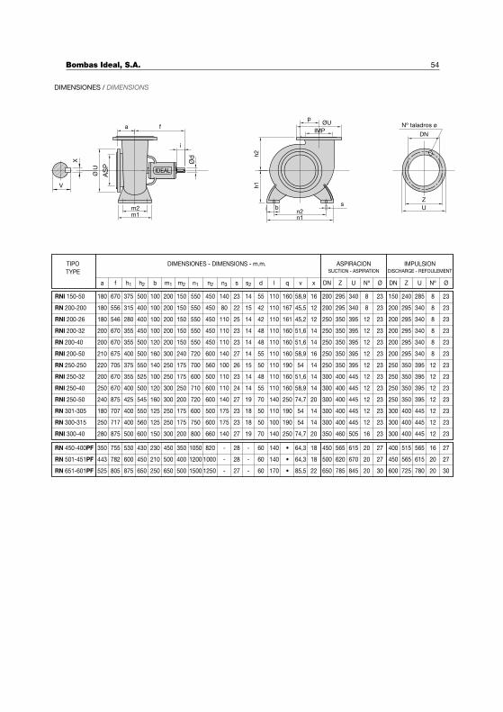
54
Nº ØUZDNØNºUZDNxvqlds2sn3n2n1m2m1bh2h1fa
IMPULSIONDISCHARGE - REFOULEMENT
ASPIRACIONSUCTION - ASPIRATION
DIMENSIONES - DIMENSIONS - m.m.TIPO
TYPE
RN 450-400PF
RN 501-451PF
RN 651-601PF
350
443
525
755
782
805
530
600
875
430
450
650
230
210
250
450
500
650
350
400
500
1050
1200
1500
820
1000
1250
-
-
-
28
28
27
-
-
-
60
60
60
140
140
170
64,3
64,3
85,5
18
18
22
450
500
650
565
620
785
615
670
845
20
20
20
27
27
30
400
450
600
515
565
725
565
615
780
16
20
20
27
27
30
RN 200-200
RNI 200-26
RNI 200-32
RN 200-40
RNI 200-50
RNI 250-32
RN 301-305
RN 300-315
180
180
200
200
210
200
180
250
556
546
670
670
675
670
707
717
315
280
355
355
400
355
400
400
400
400
450
500
500
525
550
560
100
100
100
120
160
100
125
125
200
200
200
200
300
250
250
250
150
150
150
150
240
175
175
175
550
550
550
550
720
600
600
750
450
450
450
450
600
500
500
600
80
110
110
110
140
110
175
175
22
25
23
23
27
23
23
23
15
14
14
14
14
14
18
18
42
42
48
48
55
48
50
50
110
110
110
110
110
110
110
100
45,5
45,2
51,6
51,6
58,9
51,6
54
54
12
12
14
14
16
14
14
14
200
250
250
250
250
300
300
300
295
350
350
350
350
400
400
400
340
395
395
395
395
445
445
445
8
12
12
12
12
12
12
12
23
23
23
23
23
23
23
23
200
200
200
200
200
250
300
300
295
295
295
295
295
350
400
400
340
340
340
340
340
395
445
445
8
8
8
8
8
12
12
12
23
23
23
23
23
23
23
23
RNI 250-40
RNI 250-50
RN 250-250 220 705 375 550 140 250 175 700 560 100 26 15 50 110 54 14 250 350 395 12 23 250 350 395 12 23
250 670 400 500 120 300 250 710 600 110 24 14 55 110 58,9 14 300 400 445 12 23 250 350 395 12 23
240 875 425 545 160 300 200 720 600 140 27 19 70 140 74,7 20 300 400 445 12 23 250 350 395 12 23
RNI 300-40 280 875 500 600 150 300 200 800 660 140 27 19 70 140 74,7 20 350 460 505 16 23 300 400 445 12 23
RNI 150-50 180 670 375 500 100 200 150 550 450 140 23 14 55 110 58,9 16 200 295 340 8 23 150 240 285 8 23
•
167
161
160
160
160
160
190
190
190
160
250
250
160
•
•
DIMENSIONES / DIMENSIONS
a f
IDEAL
V
X
Ø U
m1
AS
P
m2
i
Ød
n1n2
sb
IMP
ØU
h2
h1
p
U
Z
DN
Nº taladros ø
Bombas Ideal, S.A.
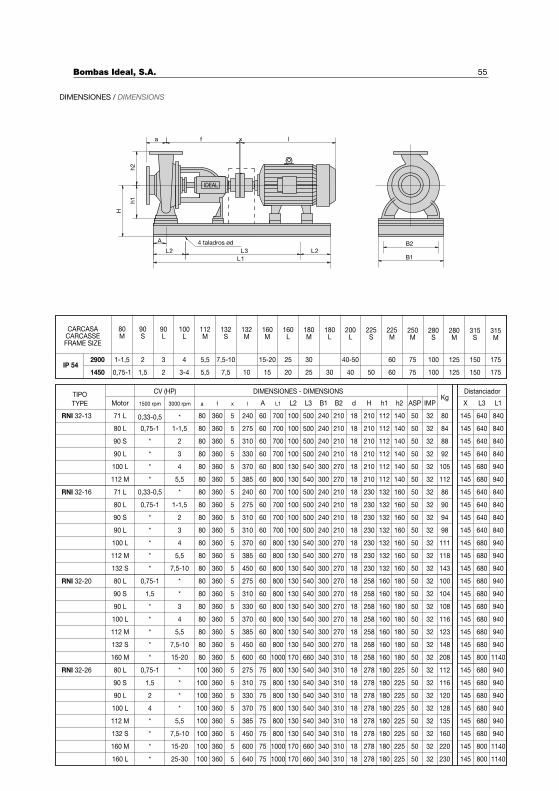
55
CARCASACARCASSEFRAME SIZE
DistanciadorDIMENSIONES - DIMENSIONSTIPO
TYPE Motor 1500 rpm 3000 rpm a f x l A L1 L2 L3 B1 B2 d H h1 h2 ASP IMPKg
X L3 L1
CV (HP)
DIMENSIONES / DIMENSIONS
IDEAL
a f x l
h2
h1
H
A
L2 L3 L2
L1
4 taladros ød B2
B1
80
2900
RNI 32-16
RNI 32-20
RNI 32-26
80 L
90 S
90 L
100 L
112 M
71 L
80 L
90 S
90 L
100 L
112 M
132 S
80 L
90 S
90 L
100 L
112 M
132 S
160 M
80 L
90 S
90 L
100 L
112 M
132 S
160 M
0,75-1
*
*
*
*
0,33-0,5
0,75-1
*
*
*
*
*
0,75-1
1,5
*
*
*
*
*
0,75-1
1,5
2
4
*
*
*
1-1,5
2
3
4
5,5
*
1-1,5
2
3
4
5,5
7,5-10
*
*
3
4
5,5
7,5-10
15-20
*
*
*
*
5,5
7,5-10
15-20
80
80
80
80
80
80
80
80
80
80
80
80
80
80
80
80
80
80
100
100
100
100
100
100
100
5
5
5
5
5
5
5
275
310
330
370
385
240
275
310
310
370
385
450
275
310
330
370
385
450
600
275
310
330
370
385
450
600
60
60
60
60
60
60
60
60
60
60
60
60
60
60
60
60
60
60
60
75
75
75
75
75
75
75
700
700
700
800
800
700
700
700
700
800
800
800
800
800
800
800
800
800
1000
800
800
800
800
800
800
1000
100
100
100
130
130
100
100
100
100
130
130
130
130
130
130
130
130
130
170
130
130
130
130
130
130
170
500
500
500
540
540
500
500
500
500
540
540
540
540
540
540
540
540
540
660
540
540
540
540
540
540
660
240
240
240
300
300
240
240
240
240
300
300
300
300
300
300
300
300
300
340
340
340
340
340
340
340
340
210
210
210
270
270
210
210
210
210
270
270
270
270
270
270
270
270
270
310
310
310
310
310
310
310
310
18
18
18
18
18
18
18
18
18
18
18
18
18
18
18
18
18
18
18
18
18
18
18
18
18
18
210
210
210
210
210
230
230
230
230
230
230
230
258
258
258
258
258
258
258
278
278
278
278
278
278
278
112
112
112
112
112
132
132
132
132
132
132
132
160
160
160
160
160
160
160
180
180
180
180
180
180
180
140
140
140
140
140
160
160
160
160
160
160
160
180
180
180
180
180
180
180
225
225
225
225
225
225
225
50
50
50
50
50
50
50
50
50
50
50
50
50
50
50
50
50
50
50
50
50
50
50
50
50
50
32
32
32
32
32
32
32
32
32
32
32
32
32
32
32
32
32
32
32
32
32
32
32
32
32
32
84
88
92
105
112
86
90
94
98
111
118
143
100
104
108
116
123
148
208
112
116
120
128
135
160
220
145
145
145
145
145
145
145
145
145
145
145
145
145
145
145
145
145
145
145
145
145
145
145
145
145
145
640
640
640
680
680
640
640
640
640
680
680
680
680
680
680
680
680
680
800
680
680
680
680
680
680
800
840
840
840
940
940
840
840
840
840
940
940
940
940
940
940
940
940
940
1140
940
940
940
940
940
940
1140
160 L * 25-30 100 640 75 1000 170 660 340 310 18 278 180 225 50 32 230 145 800 1140
1450
80M
1-1,5
0,75-1
90S
2
1,5
90L
3
2
100L
4
3-4
112M
5,5
5,5
7,5-10
132S
7,5
132M
10
160M
15-20
15
160L
25
20
30
180M
25
180L
30
40-50
200L
40
225S
50
225M
60
60
250M
75
75
280S
100
100
280M
125
125
315S
150
150
315M
175
175IP 54
RNI 32-13 71 L 0,33-0,5 * 80 360 5 240 60 700 100 500 240 210 18 210 112 140 50 32 80 145 640 840
5
5
5
5
5
5
5
5
5
5
5
5
5
5
5
5
5
5
5
5
360
360
360
360
360
360
360
360
360
360
360
360
360
360
360
360
360
360
360
360
360
360
360
360
360
360
360
Bombas Ideal, S.A.
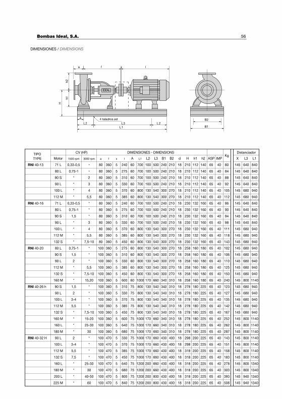
56
DistanciadorDIMENSIONES - DIMENSIONSTIPO
TYPE Motor 1500 rpm 3000 rpm a f x l A L1 L2 L3 B1 B2 d H h1 h2 ASP IMPKg
X L3 L1
CV (HP)
RNI 40-13 71 L
80 L
90 S
90 L
0,33-0,5
0,75-1
*
*
*
*
2
3
80
80
80
80
360
360
360
360
5 240
275
310
330
60
60
60
60
700
700
700
700
100
100
100
100
500
500
500
500
240
240
240
240
210
210
210
210
18 210
210
210
210
112
112
112
112
140
140
140
140
65 40 80
84
88
92
145
145
145
145
640
640
640
640
840
840
840
840
100 L * 4 80 360 370 60 800 130 540 300 270 210 112 140 105 145 680 940
112 M * 5,5 80 360 385 60 800 130 540 300 270 210 112 140 112 145 680 940
RNI 40-16 71 L 0,33-0,5 * 80 360 240 60 700 100 500 240 210 230 132 160 86 145 640 840
80 L 0,75-1 * 80 360 275 60 700 100 500 240 210 230 132 160 90 145 640 840
90 S 1,5 * 80 360 310 60 700 100 500 240 210 230 132 160 94 145 640 840
90 L * 3 80 360 330 60 700 100 500 240 210 230 132 160 98 145 640 840
100 L * 4 80 360 370 60 800 130 540 300 270 230 132 160 111 145 680 940
112 M * 5,5 80 360 385 60 800 130 540 300 270 230 132 160 118 145 680 940
132 S * 7,5-10 80 360 450 60 800 130 540 300 270 230 132 160 143 145 680 940
RNI 40-20 80 L 0,75-1 * 100 360 275 60 800 130 540 300 270 258 160 180 102 145 680 940
90 S 1,5 * 100 360 310 60 800 130 540 300 270 258 160 180 106 145 680 940
90 L 2 * 100 360 330 60 800 130 540 300 270 258 160 180 110 145 680 940
112 M * 5,5 100 360 385 60 800 130 540 300 270 258 160 180 125 145 680 940
132 S * 7,5-10 100 360 450 60 800 130 540 300 270 258 160 180 150 145 680 940
160 M * 15,20 100 360 600 60 1000 170 660 340 310 258 160 180 240 145 800 1140
RNI 40-26 h 90 S 1,5 * 100 360 310 75 800 130 540 340 310 278 180 225 123 145 680 940
90 L 2 * 100 360 330 75 800 130 540 340 310 278 180 225 127 145 680 940
100 L 3-4 * 100 360 370 75 800 130 540 340 310 278 180 225 135 145 680 940
112 M 5,5 * 100 360 385 75 800 130 540 340 310 278 180 225 142 145 680 940
132 S * 7,5-10 100 360 450 75 800 130 540 340 310 278 180 225 167 145 680 940
160 M * 15-20 100 360 600 75 1000 170 660 340 310 278 180 225 252 145 800 1140
160 L * 25-30 100 360 640 75 1000 170 660 340 310 278 180 225 262 145 800 1140
180 M * 30 100 360 680 75 1000 170 660 340 310 278 180 225 287 145 800 1140
RNI 40-32 H 90 L 2 * 100 470 330 75 1000 170 660 430 400 298 200 225 143 145 800 1140
100 L 3-4 * 100 470 370 75 1000 170 660 430 400 298 200 225 151 145 800 1140
112 M 5,5 * 100 470 385 75 1000 170 660 430 400 318 200 225 158 145 800 1140
132 S 7,5 * 100 470 450 75 1000 170 660 430 400 318 200 225 183 145 800 1140
160 L * 25-30 100 470 640 75 1200 200 660 430 400 318 200 225 278 145 800 1340
180 M * 30 100 470 680 75 1200 200 660 430 400 318 200 225 303 145 800 1340
200 L * 40-50 100 470 800 75 1200 200 800 430 400 318 200 225 393 145 940 1340
225 M * 60 100 470 840 75 1200 200 800 430 400 318 200 225 508 145 940 1340
18 65 40
18 65 40
18 65 40
18 65 40
18 65 40
18 65 40
18 65 40
18 65 40
18 65 40
18 65 40
18 65 40
18 65 40
18 65 40
18 65 40
18 65 40
18 65 40
18 65 40
18 65 40
18 65 40
18 65 40
18 65 40
18 65 40
18 65 40
18 65 40
18 65 40
18 65 40
18 65 40
18 65 40
18 65 40
18 65 40
18 65 40
18 65 40
18 65 40
18 65 40
5
5
5
5
5
5
5
5
5
5
5
5
5
5
5
5
5
5
5
5
5
5
5
5
5
5
5
5
5
5
5
5
5
5
DIMENSIONES / DIMENSIONS
IDEAL
a f x lh
2h
1
H
A
L2 L3 L2
L1
4 taladros ød B2
B1
Bombas Ideal, S.A.
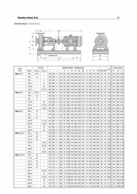
57
DistanciadorDIMENSIONES - DIMENSIONSTIPO
TYPE Motor 1500 rpm 3000 rpm a f x l A L1 L2 L3 B1 B2 d H h1 h2 ASP IMPKg
X L3 L1
CV (HP)
DIMENSIONES / DIMENSIONS
IDEAL
a f x lh
2h
1
H
A
L2 L3 L2
L1
4 taladros ød B2
B1
RNI 50-16
RNI 50-20
RNI 50-26 h
RNI 50-32 H
90 S
90 L
100 L
112 M
132 S
80 L
90 S
90 L
112 M
132 S
160 M
90 S
90 L
100 L
132 S
160 M
160 L
180 M
100 L
112 M
132 S
160 M
160 L
180 M
200 L
100 L
132 S
132 M
160 M
160 L
1,5
*
*
*
*
0,75-1
1,5
2
*
*
*
1,5
2
3-4
*
*
*
*
3-4
5,5
7,5
*
*
*
*
3,4
7,5
10
15
*
*
3
4
5,5
7,5-10
*
*
*
5,5
7,5-10
15,20
*
*
*
7,5-10
15-20
25
30
*
*
*
15-20
25-30
30
40-50
*
*
*
*
25-30
100
100
100
100
100
100
100
100
100
100
100
100
100
100
100
100
100
100
100
100
100
100
100
100
100
125
125
125
125
125
470
470
470
470
310
330
370
385
450
275
310
330
385
450
600
310
330
370
450
600
640
680
370
385
450
600
640
680
800
370
450
480
600
640
60
60
60
60
60
60
60
60
60
60
60
60
60
60
60
60
60
60
75
75
75
75
75
75
75
75
75
75
75
75
700
700
800
800
800
800
800
800
800
800
1000
800
800
800
800
1000
1000
1000
800
800
800
1000
1000
1000
1200
1000
1000
1000
1000
1000
100
100
130
130
130
130
130
130
130
130
170
130
130
130
130
170
170
170
130
130
130
170
170
170
200
170
170
170
170
170
500
500
540
540
540
540
540
540
540
540
660
540
540
540
540
660
660
660
540
540
540
660
660
660
800
660
660
660
660
660
240
240
300
300
300
300
300
300
300
300
340
300
300
300
300
340
340
430
340
340
340
340
340
340
430
430
430
430
430
430
210
210
270
270
270
270
270
270
270
270
310
270
270
270
270
310
310
400
310
310
310
310
310
310
400
400
400
400
400
400
230
230
230
230
230
258
258
258
258
258
258
258
258
258
258
258
258
298
278
278
278
278
278
278
318
323
345
345
345
345
132
132
132
132
132
160
160
160
160
160
160
160
160
160
160
160
160
160
180
180
180
180
180
180
180
225
225
225
225
225
160
160
160
160
160
180
180
180
180
180
180
200
200
200
200
200
200
200
225
225
225
225
225
225
225
280
280
280
280
280
93
97
110
117
142
100
104
108
123
148
238
108
112
120
152
242
252
277
136
143
168
253
263
288
378
152
184
189
269
279
640
640
680
680
680
680
680
680
680
680
800
680
680
680
680
800
800
800
680
680
680
800
800
800
940
800
800
800
800
800
840
840
940
940
940
940
940
940
940
940
1140
940
940
940
940
1140
1140
1140
940
940
940
1140
1140
1140
1340
1140
1140
1140
1140
1140
112 M 5,5 * 125 385 75 1000 170 660 430 400 323 225 280 159 800 1140
180 M * 30 125 470 680 75 1200 200 800 430 400 345 225 280 304 940 1340
200 L * 40-50 125 470 800 75 1200 200 800 430 400 345 225 280 396 940 1340
225 M * 60 125 470 840 75 1400 230 940 600 560 363 225 280 511 1080 1540
250 M * 75 125 470 930 75 1400 230 940 600 560 388 225 280 611 1080 1540
280 S * 100 125 470 990 75 1400 230 940 600 560 418 225 280 761 1080 1540
RNI 50-13 80 L 0,75-1 * 100 360 5 275 60 700 100 500 240 210 18 230 132 160 65 50 89 145 640 840
360
360
360
360
360
360
360
360
360
360
360
360
360
360
360
360
360
360
360
360
360
360
360
360
360
470
470
18
18
18
18
18
18
18
18
18
18
18
18
18
18
18
18
18
18
18
18
18
18
18
18
18
18
18
18
18
18
18
18
18
23
23
23
65 50 145
65 50 145
65 50 145
65 50 145
65 50 145
65 50 145
65 50 145
65 50 145
65 50 145
65 50 145
65 50 145
65 50 145
65 50 145
65 50 145
65 50 145
65 50 145
65 50 145
65 50 145
65 50 145
65 50 145
65 50 145
65 50 145
65 50 145
65 50 145
65 50 145
65 50 145
65 50 145
65 50 145
65 50 145
65 50 145
65 50 145
65 50 145
65 50 145
65 50 145
65 50 145
65 50 145
5
5
5
5
5
5
5
5
5
5
5
5
5
5
5
5
5
5
5
5
5
5
5
5
5
5
5
5
5
5
5
5
5
5
5
5
Bombas Ideal, S.A.
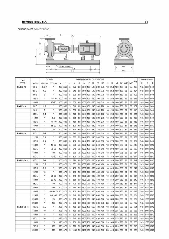
58
DistanciadorDIMENSIONES - DIMENSIONSTIPO
TYPE Motor 1500 rpm 3000 rpm a f x l A L1 L2 L3 B1 B2 d H h1 h2 ASP IMPKg
X L3 L1
CV (HP)
RNI 65-13 80 L 0,75-1 * 100 360 275 60 800 130 540 300 270 258 160 180 100 145 680 940
90 S 1,5 * 100 360 310 60 800 130 540 300 270 258 160 180 104 680 940
90 L 2 * 100 360 330 60 800 130 540 300 270 258 160 180 108 680 940
132 S * 7,5-10 100 360 450 60 800 130 540 300 270 258 160 180 148 680 940
160 M * 15-20 100 360 600 60 1000 170 660 340 310 258 160 180 238 800 1140
RNI 65-16 90 S 1,5 * 100 360 310 60 800 130 540 300 270 258 160 200 109 680 940
90 L 2 * 100 360 330 60 800 130 540 300 270 258 160 200 113 680 940
100 L 3-4 * 100 360 370 60 800 130 540 300 270 258 160 200 121 680 940
112 M * 5,5 100 360 385 60 800 130 540 300 270 258 160 200 128 680 940
132 S * 7,5-10 100 360 450 60 800 130 540 300 270 258 160 200 153 680 940
160 M * 15-20 100 360 600 60 1000 170 660 340 310 258 160 200 243 800 1140
160 L * 25 100 360 640 60 1000 170 660 340 310 258 160 200 253 800 1140
RNI 65-20 100 L 3-4 * 100 360 370 75 800 130 540 340 310 278 180 225 132 680 940
112 M 5,5 * 100 360 385 75 800 130 540 340 310 278 180 225 139 680 940
132 S 7,5 * 100 360 450 75 800 130 540 340 310 278 180 225 164 680 940
160 M * 15-20 100 360 600 75 1000 170 660 340 310 278 180 225 249 800 1140
160 L * 25-30 100 360 640 75 1000 170 660 340 310 278 180 225 259 800 1140
180 M * 30 100 360 680 75 1000 170 660 340 310 278 180 225 284 800 1140
200 L * 40-50 100 360 800 75 1000 200 800 430 400 318 180 225 274 940 1340
RNI 65-26 h 100 L 3-4 * 100 470 370 90 1000 170 660 430 400 318 200 250 217 800 1140
112 M 5,5 * 100 470 385 90 1000 170 660 430 400 318 200 250 224 800 1140
132 S 7,5 * 100 470 450 90 1000 170 660 430 400 318 200 250 249 800 1140
132 M 10 * 100 470 480 90 1000 170 660 430 400 318 200 250 254 800 1140
160 L * 25-30 100 470 640 90 1200 200 800 430 400 318 200 250 324 940 1340
180 M * 30-40 100 470 680 90 1200 200 800 430 400 318 200 250 349 940 1340
180 L * 50 100 470 720 90 1200 200 800 430 400 318 200 250 374 940 1340
18 80 655
200 M * 60 100 470 770 90 1200 200 800 430 400 318 200 250 429 940 1340
200 M * 40-50-75 100 470 800 90 1200 200 800 430 400 318 200 250 439 940 1340
225 M * 60-100 100 470 840 90 1400 230 940 600 560 363 200 250 554 1080 1540
250 M * 75 100 470 930 90 1400 230 940 600 560 388 200 250 654 1080 1540
280 M * 100 100 470 990 90 1400 230 940 600 570 418 200 250 707 1080 1540
18
18
18
18
18
18
18
18
18
18
18
18
18
18
18
18
18
18
18
18
18
18
18
18
18
18
18
18
18
23
14580 65
14580 65
14580 65
14580 65
14580 65
14580 65
14580 65
14580 65
14580 65
14580 65
14580 65
14580 65
14580 65
14580 65
14580 65
14580 65
14580 65
14580 65
14580 65
14580 65
14580 65
14580 65
14580 65
14580 65
14580 65
14580 65
14580 65
14580 65
14580 65
14580 65
5
5
5
5
5
5
5
5
5
5
5
5
5
5
5
5
5
5
5
5
5
5
5
5
5
5
5
5
5
5
132 M
160 M
160 L
250 M
280 S
280 M
10
15
20
*
*
*
*
*
*
75
100
125
480
600
640
930
990
1040
1000
1200
1200
1400
1400
1400
170
200
200
230
230
230
660
800
800
940
940
940
430
430
430
600
600
600
400
400
400
560
560
560
18
18
18
23
23
23
343
343
343
388
418
418
266
326
336
666
816
866
800
940
940
1080
1080
1080
1140
1340
1340
1540
1540
1540
132 S 7,5 * 125 470 5 450 90 1000 170 660 430 400 18 343 225 280 80 65 261 145 800 1140
125 470 5 225 280 80 65 145
125 470 5 225 280 80 65 145
125 470 5 225 280 80 65 145
125 470 5 225 280 80 65 145
125 470 5 225 280 80 65 145
125 470 5 225 280 80 65 145
90
90
90
90
90
90
RNI 65-32 H
DIMENSIONES / DIMENSIONS
IDEAL
a f x l
h2
h1
H
A
L2 L3 L2
L1
4 taladros ød B2
B1
Bombas Ideal, S.A.
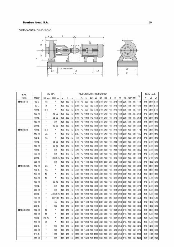
59
DistanciadorDIMENSIONES - DIMENSIONSTIPO
TYPE Motor 1500 rpm 3000 rpm a f x l A L1 L2 L3 B1 B2 d H h1 h2 ASP IMPKg
X L3 L1
CV (HP)
90 S
90 L
100 L
160 M
160 L
180 M
200 L
100 L
112 M
132 S
160 L
180 M
180 L
200 M
200 L
225 M
112 M
132 S
132 M
160 M
180 L
200 M
200 L
225 M
1,5
2
3-4
*
*
*
*
3-4
5,5
7,5
*
*
*
*
*
*
5,5
7,5
10
15
*
*
*
*
*
*
*
15-20
25-30
30
40-50
*
*
*
25-30
30-40
50
60
40-50-75
60
*
*
*
*
50
60
40-50-75
60-100
125 5 310
330
370
600
640
680
800
370
385
450
640
680
720
770
800
840
385
450
480
600
720
770
800
840
75
75
75
75
75
75
75
75
75
75
75
75
75
75
75
75
90
90
90
90
90
90
90
90
800
800
800
1000
1000
1000
1200
1000
1000
1000
1200
1200
1200
1200
1200
1400
1000
1000
1000
1200
1200
1200
1200
1400
130
130
130
170
170
170
200
170
170
170
200
200
200
200
200
230
170
170
170
200
200
200
200
230
540
540
540
660
660
660
800
660
660
660
800
800
800
800
800
940
660
660
660
800
800
800
800
940
340
340
340
340
340
340
430
340
340
340
430
430
430
430
430
600
430
430
430
430
430
430
430
600
310
310
310
310
310
310
400
310
310
310
400
400
400
400
400
560
400
400
400
400
400
400
400
560
18
18
18
18
18
18
18
18
18
18
18
18
18
18
18
23
18
18
18
18
18
278
278
278
278
278
278
278
278
278
278
298
298
298
318
318
363
318
318
318
318
318
318
318
363
180
180
180
180
180
180
180
180
180
180
180
180
180
180
180
180
200
200
200
200
200
200
200
200
225
225
225
225
225
225
225
250
250
250
250
250
250
250
250
250
280
280
280
280
280
280
280
280
80
80
80
80
80
80
100
65
65
65
65
65
65
80
119
123
131
248
258
283
348
178
185
210
315
340
365
420
430
545
223
248
253
313
373
428
438
553
145 680
680
680
800
800
800
940
800
800
800
940
940
940
940
940
1080
800
800
800
940
940
940
940
1080
180 M * 30-40 680 90 1200 200 800 430 400 18 318 200 280 348 940
250 M * 75 930 90 1400 230 940 600 560 388 200 280 653 1080
280 S * 100 990 90 1400 230 940 600 560 418 200 280 803 1080
132 M 10 * 480 90 1000 170 660 430 400 368 250 315 265 800
160 M 15 * 600 90 1200 200 800 430 400 368 250 315 330 940
160 L 20-25 * 640 90 1200 200 800 430 400 368 250 315 340 940
180 M 25 * 680 90 1200 200 800 430 400 368 250 315 365 940
280 S * 100 990 90 1400 230 940 600 560 420 250 315 820 1080
280 M * 125 1040 90 1400 230 940 600 560 420 250 315 870 1080
315 S * 150 1130 90 1500 250 1000 700 660 485 250 315 1170 1140
315 M * 175 1180 90 1500 250 1000 700 660 485 250 315 1470 1140
360
360
360
360
360
360
360
470
18
18
23
23
23
18
18
18
18
23
23
23
23
940
940
940
1140
1140
1140
1340
1140
1140
1140
1340
1340
1340
1340
1340
1540
1140
1140
1140
1340
1340
1340
1340
1540
1340
1540
1540
1140
1340
1340
1340
1540
1540
1640
1640
145
145
145
145
145
145
145
145
145
145
145
145
145
145
145
145
145
145
145
145
145
145
145
145
145
145
145
145
145
145
145
145
145
145
100 80
100 80
100 80
100 80
100 80
100 80
100 80
100 80
100 80
100 80
100 80
100 80
100 80
100 80
100 80
100 80
100 80
100 80
100 80
100 80
100 80
100 80
100 80
100 80
100 80
100 80
100 80
100 80
125 5
125 5
125 5
125 5
125 5
125 5
125 5
125 5
125 5
125 5
125 5
125 5
125 5
125 5
125 5
125 5
125 5
125 5
125 5
125 5
125 5
125 5
125 5
125 5
125 5
125 5
125 5
125 5
125 5
125 5
125 5
125 5
125 5
125 5
470
470
470
470
470
470
470
470
470
470
470
470
470
470
470
470
470
470
470
470
470
470
470
470
470
470
470
RNI 80-16
RNI 80-20
RNI 80-26 h
RNI 80-32 H
DIMENSIONES / DIMENSIONS
IDEAL
a f x l
h2
h1
H
A
L2 L3 L2
L1
4 taladros ød B2
B1
Bombas Ideal, S.A.
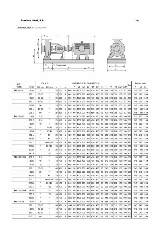
60
DistanciadorDIMENSIONES - DIMENSIONSTIPO
TYPE Motor 1500 rpm 3000 rpm a f x l A L1 L2 L3 B1 B2 d H h1 h2 ASP IMPKg
X L3 L1
CV (HP)
160 M 15 * 125 530 600 90 1200 200 800 430 400 398 280 355 372 145 940 1340
160 L 20-25 * 125 530 640 1200 200 800 430 400 398 280 355 390 940 1340
180 M 25-30 * 125 530 680 1200 200 800 430 400 398 280 355 407 940 1340
180 L 30-40 * 125 530 720 1200 200 800 430 400 398 280 355 440 940 1340
200 M 50 * 125 530 760 1400 230 940 550 510 398 280 355 995 1080 1540
200 L 40-60 * 125 530 800 1400 230 940 550 510 398 280 355 507 1080 1540
225 S 50 * 125 530 840 1400 230 940 550 510 420 280 355 550 1080 1540
112 M 5,5 * 125 470 385 1000 170 660 430 400 318 200 280 225 800 1140
132 S 7,5 * 125 470 450 1000 170 660 430 400 318 200 250 800 1140
132 M 10 * 125 480 1000 170 660 430 400 318 200 255 800 1140
160 L * 25-30 125 640 1200 200 800 430 400 318 200 315 940 1340
180 M * 30-40 125 680 1200 200 800 430 400 318 200 350 940 1340
180 L * 50 125 720 1200 200 800 430 400 318 200 375 940 1340
200 M * 60 125 770 1200 200 800 430 400 318 200 430 940 1340
200 L * 40-50-75 125 800 1200 200 800 430 400 318 200 440 940 1340
225 M * 60-100 125 840 1400 230 940 600 560 363 200 555 1080 1540
250 M * 75 125 930 1400 230 940 600 560 388 200 655 1080 1540
280 S * 100 125 990 1400 230 940 600 560 418 200 805 1080 1540
132 S 7,5 * 140 450 1000 170 660 430 400 343 225 257 800 1140
132 M 10 * 480 1000 170 660 430 400 343 262 800 1140
160 M 15 * 600 1200 200 800 430 400 343 322 940 1340
18 100 80
18 100 80
18 100 80
18 100 80
18 100 80
18 100 80
100 8023
125 10018
100
18 100
18
18
18
18
18
23
23
23
18
18
5
160 L 20-25 * 640 1200 200 800 430 400 343 332 940 134018
180 M 30 * 680 1200 200 800 430 400 343 357 940 134018
200 M * 60 770 1200 200 800 430 400 343 437 940 134018
200 L * 40-50-70 800 1200 200 800 430 400 343 447 940 134018
225 M * 60-100 840 1400 230 940 600 560 363 562 1080 154023
250 S * 125 880 1400 230 940 600 560 388 622 1080 154023
RNI 80-40
RNI 100-20
RNI 100-26 H
18
18
145
145
145
145
145
145
145
145
145
145
145
145
145
145
145
145
145
145
145
145
145
145
145
145
145
145
100
100
100
100
100
100
100
100
100
100
100
100
100
100
100
100
100
225
225
225
225
225
225
225
225
140
140
140
140
140
140
140
140
470
470
470
470
470
470
470
470
470
470
470
470
470
470
470
470
470
470
905
905
905
905
905
905
905
905
905
905
905
905
905
905
905
905
905
905
905
905
905
905
905
905
905
905
280 125
280 125
280 125
280 125
280 125
280 125
280 125
280 125
280 125
280 125
280 125
280 125
280 125
280 125
280 125
280 125
280 125
280 125
280 125
DIMENSIONES / DIMENSIONS
IDEAL
a f x lh
2h
1
H
A
L2 L3 L2
L1
4 taladros ød B2
B1
RNI 100-32
280 S
280 M
160 M
160 L
180 M
180 L
200 L
*
*
15
20-25
25-30
30-40
40
125
*
*
*
*
*
*
990
1040
600
640
680
720
800
1400
1400
1200
230
230
200
940
940
800
600
600
430
560
560
400
400
400
400
400
23
23
18
18
18
18
18
418
418
368
368
368
368
368
225
225
250
250
250
250
250
280
280
315
315
315
315
315
812
862
340
350
375
400
465
1080
1080
940
940
940
940
940
1540
1540
1340
1340
1340
1340
1340
RNI 100-26 H 250 M * 75 140 470 5 930 90 1400 230 940 600 560 23 388 225 280 125 100 662 145 1080 1540
140 470 5 90 125 100 145
140 470 5 90 125 100 145
140 470 5 90 125 100 145
140 470 5 90 125 100 145
140 470 5 90 125 100 145
140 470 5 90 125 100 145
140 470 5 90 125 100 145
1200 200 800 430
1200 200 800 430
1200 200 800 430
1200 200 800 430
Bombas Ideal, S.A.
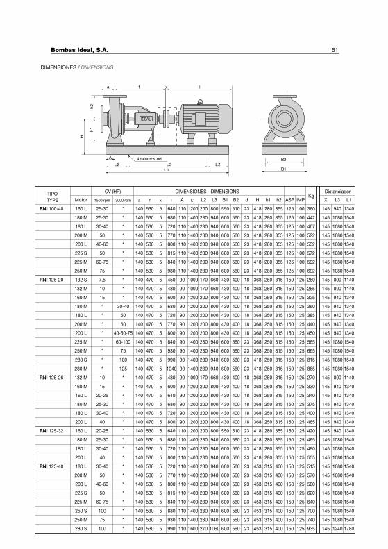
61
DistanciadorDIMENSIONES - DIMENSIONSTIPO
TYPE Motor 1500 rpm 3000 rpm a f x l A L1 L2 L3 B1 B2 d H h1 h2 ASP IMPKg
X L3 L1
CV (HP)
DIMENSIONES / DIMENSIONS
IDEAL
a f x lh
2h
1
H
A
L2 L3 L2
L1
4 taladros ød B2
B1
RNI 100-40
RNI 125-20
160 L
180 M
180 L
200 M
200 L
225 S
225 M
250 M
132 S
132 M
160 M
180 M
180 L
200 M
200 L
225 M
250 M
280 S
280 M
160 M
160 L
180 M
180 L
25-30
25-30
30-40
50
40-60
50
60-75
75
7,5
10
15
*
*
*
*
*
*
*
*
15
20-25
25-30
30-40
*
*
*
*
*
*
*
*
*
*
*
30-40
50
60
40-50-75
60-100
75
100
125
*
*
*
*
140
470
470
470
470
640
680
720
770
800
815
840
930
450
480
600
680
720
770
800
840
930
990
1040
600
640
680
720
110
110
110
110
110
110
110
110
90
90
90
90
90
90
90
90
90
90
90
90
90
90
90
1200
1400
1400
1400
1400
1400
1400
1400
1000
1000
1200
1200
1200
1200
1200
1400
1400
1400
1400
1200
1200
1200
1200
200
230
230
230
230
230
230
230
170
170
200
200
200
200
200
230
230
230
230
200
200
200
200
800
940
940
940
940
940
940
940
660
660
800
800
800
800
800
940
940
940
940
800
800
800
800
550
600
600
600
600
600
600
600
430
430
430
430
430
430
430
600
600
600
600
430
430
430
430
510
560
560
560
560
560
560
560
400
400
400
400
400
400
400
560
560
560
560
400
400
400
400
23
23
23
23
23
23
23
23
18
18
18
18
18
18
18
23
23
23
23
18
418
418
418
418
418
418
418
418
368
368
368
368
368
368
368
368
368
418
418
368
368
368
368
280
280
280
280
280
280
280
280
250
250
250
250
250
250
250
250
250
250
250
250
250
250
250
355
355
355
355
355
355
355
355
315
315
315
315
315
315
315
315
315
315
315
315
315
315
315
125
125
125
125
125
125
125
125
150
100
100
100
100
100
100
100
100
125
360
442
467
522
532
572
592
692
260
265
325
360
385
440
450
565
665
815
865
330
340
375
400
145 940
1080
1080
1080
1080
1080
1080
1080
800
800
940
940
940
940
940
1080
1080
1080
1080
940
940
940
940
1340
1540
1540
1540
1540
1540
1540
1540
1140
1140
1340
1340
1340
1340
1340
1540
1540
1540
1540
1340
1340
1340
1340
RNI 125-26 132 M 10 * 480 90 1000 170 660 430 400 18 368 250 315 270 800 1140
200 L 40 * 470 800 90 1200 200 800 430 400 368 250 315 465 940 1340
RNI 125-32 160 L 20-25 * 530 640 110 1200 200 800 550 510 280 355 420 940 1340
180 M 25-30 * 680 1400 230 940 600 560 280 355 465 1080 1540
180 L 30-40 * 720 1400 230 940 418 280 355 490 1080 1540
200 L 40 * 800 1400 230 940 418 280 355 555 1080 1540
RNI 125-40 180 L 30-40 * 720 1400 230 940 453 315 400 515 1080 1540
200 M 50 * 770 1400 230 940 570 1080 1540
200 L 40-60 * 800 1400 230 940 580 1080 1540
225 S 50 * 815 1400 230 940 620 1080 1540
225 M 60-75 * 840 1400 230 940 640 1080 1540
250 S 100 * 880 1400 230 940 700 1080 1540
250 M 75 * 930 1400 230 940 740 1080 1540
280 S 100 * 990 1600 270 1060 935 1240 1780
5530
530
530
530
530
530
530
530
470
470
470
470
470
470
470
470
470
470
470
470
18
18
18
18
23
418
418
140 5
140 5
140 5
140 5
140 5
140 5
140 5
140 5
140 5
140 5
140 5
140 5
140 5
140 5
140 5
140 5
140 5
140 5
140 5
140 5
140 5
140 5
140 5
140 5
140 5
140 5
140 5
140 5
140 5
140 5
140 5
140 5
140 5
140 5
140 5
140 5
530
530
530
530
530
530
530
530
530
530
530
110
110
110
110
110
110
110
110
110
110
110
600 560
600 560
600 560
600 560
600 560
600 560
600 560
600 560
600 560
600 560
23
23
23
23
23
23
23
23
23
23
23
453 315 400
453 315 400
453 315 400
453 315 400
453 315 400
453 315 400
453 315 400
150 125
150 125
150 125
150 125
150 125
150 125
150 125
150 125
150 125
150 125
150 125
150 125
150 125
150 125
150 125
150 125
150 125
150 125
150 125
150 125
150 125
150 125
150 125
150 125
150 125
150 125
150 125
150 125
145
145
145
145
145
145
145
145
145
145
145
145
145
145
145
145
145
145
145
145
145
145
145
145
145
145
145
145
145
145
145
145
145
145
145
145
Bombas Ideal, S.A.
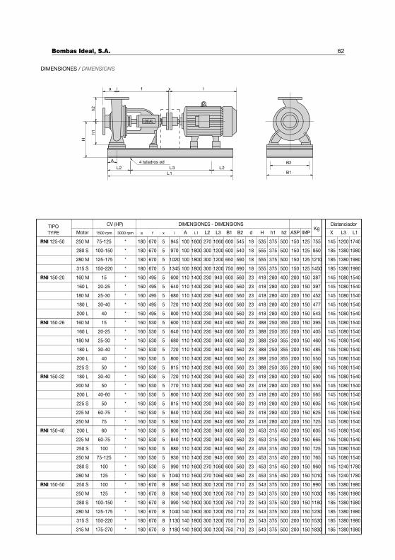
62
DIMENSIONES / DIMENSIONS
IDEAL
a f x lh
2h
1
H
A
L2 L3 L2
L1
4 taladros ød B2
B1
DistanciadorDIMENSIONES - DIMENSIONSTIPO
TYPE Motor 1500 rpm 3000 rpm a f x l A L1 L2 L3 B1 B2 d H h1 h2 ASP IMPKg
X L3 L1
CV (HP)
RNI 150-20 160 M 15 * 160 495 600 110 1400 230 940 600 560 418 280 400 387 145 1080 1540
160 L 20-25 495 640 418 280 400 397 1540
180 M 25-30 495 680 418 280 400 452 1540
180 L 30-40 495 720 418 280 400 477 1540
200 L 40 495 800 418 280 400 543 1540
RNI 150-26 160 M 15 530 600 388 250 355 395 1540
160 L 20-25 640 388 250 355 405 1540
180 M 25-30 680 388 250 355 460 1540
180 L 30-40 720 388 250 355 485 1540
200 L 40 800 388 250 355 550 1540
225 S 50 815 388 250 355 590 1540
RNI 150-32 180 L 30-40 720 418 280 400 500 1540
200 M 50 770 418 280 400 555 1540
200 L 40-60 800 418 280 400 565 1540
225 S 50 815 418 280 400 605 1540
225 M 60-75 840 418 280 400 625 1540
250 M 75 930 418 280 400 725 1540
23 200 1505
145
145
145
145
145
145
145
145
145
145
145
145
145
145
145
145
1080
1080
1080
1080
1080
1080
1080
1080
1080
1080
1080
1080
1080
1080
1080
1080
600 560 23 200 150
600 560 23 200 150
600 560 23 200 150
600 560 23 200 150
600 560 23 200 150
600 560 23 200 150
600 560 23 200 150
600 560 23 200 150
600 560 23 200 150
600 560 23 200 150
600 560 23 200 150
600 560 23 200 150
600 560 23 200 150
600 560 23 200 150
600 560 23 200 150
600 560 23 200 150
1400 230 940
1400 230 940
1400 230 940
1400 230 940
1400 230 940
1400 230 940
1400 230 940
1400 230 940
1400 230 940
1400 230 940
1400 230 940
1400 230 940
1400 230 940
1400 230 940
1400 230 940
1400 230 940
* 160 1105
* 160 1105
* 160 1105
* 160 1105
* 160 1105
* 160 1105
* 160 1105
* 160 1105
* 160 1105
* 160 1105
* 160 1105
* 160 1105
* 160 1105
* 160 1105
* 160 1105
* 160 1105
530
530
530
530
530
530
530
530
530
530
530
RNI 125-50 250 M 75-125 * 945 1600 270 1060 755 1200 1740180 5670 100 600 545 18 535 375 500 150 125 145
280 S 100-150 * 970 1800 300 1200 950 1380 1980180 5670 100 600 540 18 555 375 500 150 125 185
280 M 125-175 * 1020 1800 300 1200 1210 1380 1980180 5670 100 650 590 18 555 375 500 150 125 185
315 S 150-220 * 1345 1800 300 1200 1450 1380 1980180 5670 100 750 690 18 555 375 500 150 125 185
RNI 150-50 250 S
250 M
280 S
280 M
315 S
315 M
100
125
100-150
125-175
150-220
175-270
* 180
180
180
180
180
180
880
930
990
1040
1130
1180
140 1800
1800
1800
1800
1800
1800
300
300
300
300
300
300
1200
1200
1200
1200
1200
1200
750
750
750
750
750
750
710
710
710
710
710
710
23 543
543
543
543
543
543
375
375
375
375
375
375
500
500
500
500
500
500
200
200
200
200
200
200
150
150
150
150
150
150
990
1030
1180
1230
1530
1830
185
185
185
185
185
185
1380
1380
1380
1380
1380
1380
1980
1980
1980
1980
1980
1980
8670
670
670
670
670
670
23
23
23
23
23
* 1408
* 1408
* 1408
* 1408
* 1408
RNI 150-40 200 L 60 800 453 315 450 605 1540
225 M 60-75 840 453 315 450 665 1540
250 S 100 880 453 315 450 725 1540
250 M 75-125 930 453 315 450 765 1540
280 S 100 990 1600 270 1060 453 315 450 960 1240 1780
280 M 125 1040 1600 270 1060 453 315 450 1010 1240 1780
145
145
145
145
145
145
1080
1080
1080
1080
600 560 23 200 150
600 560 23 200 150
600 560 23 200 150
600 560 23 200 150
600 560 23 200 150
600 560 23 200 150
1400 230 940
1400 230 940
1400 230 940
1400 230 940
* 160 1105
* 160 1105
* 160 1105
* 160 1105
* 160 1105
* 160 1105
530
530
530
530
530
530
Bombas Ideal, S.A.
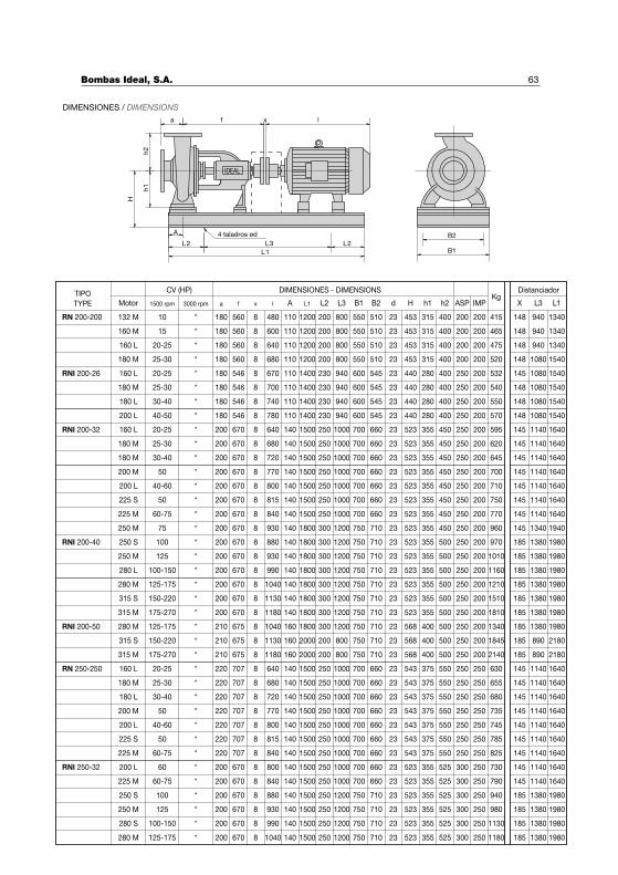
63
DistanciadorDIMENSIONES - DIMENSIONSTIPO
TYPE Motor 1500 rpm 3000 rpm a f x l A L1 L2 L3 B1 B2 d H h1 h2 ASP IMPKg
X L3 L1
CV (HP)
DIMENSIONES / DIMENSIONS
IDEAL
a f x l
h2
h1
H
A
L2 L3 L2
L1
4 taladros ød B2
B1
RN 200-200
RNI 200-26
RNI 200-32
132 M
160 M
160 L
180 M
160 L
180 M
180 L
200 L
160 L
180 M
180 M
200 L
225 S
225 M
250 M
10
15
20-25
25-30
20-25
25-30
30-40
40-50
20-25
25-30
30-40
40-60
50
60-75
75
180
180
180
180
180
180
180
180
200
200
200
200
200
200
200
670
670
670
670
480
600
640
680
670
700
740
780
640
680
720
800
815
840
930
1200
1200
1200
1200
1400
1400
1400
1400
1500
1500
1500
1500
1500
1500
1800
200
200
200
200
230
230
230
230
250
250
250
250
250
250
300
800
800
800
800
940
940
940
940
1000
1000
1000
1000
1000
1000
1200
550
550
550
550
600
600
600
600
700
700
700
700
700
700
750
510
510
510
510
545
545
545
545
660
660
660
660
660
660
710
453
453
453
453
440
440
440
440
523
523
523
523
523
523
523
315
315
315
315
280
280
280
280
355
355
355
355
355
355
355
400
400
400
400
400
400
400
400
450
450
450
450
450
450
450
200
200
200
200
250
250
250
250
250
250
250
250
200
200
200
200
200
200
200
200
200
200
200
200
415
465
475
520
532
540
550
570
595
620
645
710
750
770
960
148
148
148
148
145
148
148
148
145
145
145
145
145
145
145
940
940
940
1080
1080
1080
1080
1080
1140
1140
1140
1140
1140
1140
1340
1340
1340
1340
1540
1540
1540
1540
1540
1640
1640
1640
1640
1640
1640
1940
200 M 50 200 770 1500 250 1000 700 660 523 355 450 250 200 700 145 1140 1640
RNI 200-40 250 S 100 200 670 880 1800 300 1200 750 710 523 355 500 970 185 1380 1980
250 M 125 200 670 930 1800 300 1200 750 710 523 355 500 1010 185 1380 1980
280 L 100-150 200 670 990 1800 300 1200 750 710 523 355 500 1160 185 1380 1980
280 M 125-175 200 670 1040 1200 750 710 523 355 500 1210 185 1380 1980
315 S 150-220 200 670 1130 1200 750 710 523 355 500 1510 185 1380 1980
315 M 175-270 200 670 1180 1200 750 710 523 355 500 1810 185 1380 1980
RNI 200-50 280 M 125-175 210 675 1040 1200 750 710 568 400 500 1340 185 1380 1980
315 S 150-220 210 675 1130 800 750 710 568 400 500 1845 185 890 2180
315 M 175-270 210 675 1180 800 750 710 568 400 500 2140 185 890 2180
RN 250-250 160 L 20-25 220 707 640 1000 700 660 543 375 550 630 145 1140 1640
180 M 25-30 680 1000 700 660 655 145 1140 1640
180 L 30-40 720 1000 700 660 680 145 1140 1640
200 M 50 770 1000 700 660 735 145 1140 1640
200 L 40-60 800 1000 700 660 745 145 1140 1640
225 S 50 815 1000 700 660 785 145 1140 1640
225 M 60-75 * 220 707 840 140 1500 250 1000 700 660 543 375 550 825 145 1140 1640
RNI 250-32 200 L 60 * 200 670 800 140 1500 250 1000 700 660 523 355 525 730 145 1140 1640
225 M 60-75 * 200 670 840 140 1500 250 1000 700 660 523 355 525 790 145 1140 1640
250 S 100 * 200 670 880 140 1500 250 1200 750 710 523 355 525 940 1380 1980
250 M 125 200 670 930 140 1500 250 1200 750 710 523 355 525 980 1380 1980
280 S 100-150 200 670 990 140 1500 250 1200 750 710 523 355 525 1130 1380 1980
280 M 125-175 200 670 1040 140 1500 250 1200 750 710 523 355 525 1180 1380 1980
560
560
560
560
546
546
546
546
670
670
670
670
250 200
250 200
250 200
250 200
250 200
250 200
250
250
250
250
250
250
250
23 250 250
300 250
300 250
300 250
300 250
300 250
300 250
8
23
23
23
23
23
23
23
23
23
23
23
23
23
23
23
23
23
23
23
23
23
23
23
23
23
23
23
23
23
23
23
200
200
200
200
200
200
250
250
250
250
250
250
543 375 550 250
543 375 550 250
543 375 550 250
543 375 550 250
543 375 550 250
1800 300
1800 300
1800 300
1800 300
2000 200
2000 200
1500 250
1500 250
1500 250
1500 250
1500 250
1500 250
* 1108
* 1108
* 1108
* 1108
* 1108
* 1108
* 1108
* 1108
* 1408
* 1408
* 1408
* 1408
* 1408
* 1408
* 1408
* 1408
* 1408
* 1408
* 1408
* 1408
* 1408
* 1408
* 1608
* 1608
* 1608
* 1408
* 1408
* 1408
* 1408
* 1408
* 1408
220 707
220 707
220 707
220 707
220 707
*
*
*
185
185
185
185
238
238
238
238
238
238
Bombas Ideal, S.A.
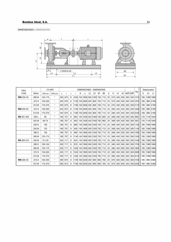
64
DistanciadorDIMENSIONES - DIMENSIONSTIPO
TYPE Motor 1500 rpm 3000 rpm a f x l A L1 L2 L3 B1 B2 d H h1 h2 ASP IMPKg
X L3 L1
CV (HP)
RNI 250-40 280 M 125-175 250 670 1040 150 1800 300 1200 750 710 570 400 500 1575 1380 1980
315 S 150-220 * 250 670 1130 150 2000 200 800 750 710 570 400 500 1875 890 2180
315 M 175-270 * 250 670 1180 150 2000 200 800 750 710 570 400 500 2175 890 2180
RNI 250-50 315 S 150-220 * 240 875 1130 150 2000 200 800 750 710 595 425 545 1946 890 2180
315 M 175-270 * 240 875 1180 150 2000 200 800 750 710 595 425 545 2245 890 2180
RN 301-305 200 L 60 180 707 800 140 1500 250 1000 700 660 568 400 550 895 1140 1640
225 M 60-75 180 707 840 140 1500 250 1000 700 660 568 400 550 955 1140 1640
250 S 100 180 707 880 140 1800 300 1200 750 710 568 400 550 1105 1380 1980
250 M 125 180 707 930 140 1800 300 1200 750 710 568 400 550 1145 1380 1980
300 250
300 250
300 250
300 250
300 250
300 300
300 300
300 300
300 300
*
*
*
*
*
185
185
185
185
185
145
145
185
185
238
238
238
238
238
238
238
238
238
280 S 100 180 707 990 140 1800 300 1200 750 710 568 400 550 1295 1380 1980300 300* 185238
280 M 125-175 180 707 1140 140 1800 300 1200 750 710 568 400 550 1345 1380 1980300 300* 185238
RN 300-315 250 M 75-125 250 717 945 140 1800 300 1200 750 710 580 400 560 1549 1380 1980300 300* 185238
280 S 100-150 250 717 970 140 1800 300 1200 750 710 580 400 560 1703 1380 1980300 300* 185238
280 M 125-175 250 717 1020 140 1800 300 1200 750 710 580 400 560 1802 1380 1980300 300* 185238
315 S 150-220 250 717 1345 140 1800 300 1200 750 710 580 400 560 2080 1380 1980300 300* 185238
315 M 175-270 250 717 1345 140 1800 300 1200 750 710 580 400 560 2216 1380 1980300 300* 185238
RNI 300-40 315 S 150-220 280 875 1130 160 2200 200 900 800 760 670 500 600 2100 990 2380350 300* 185238
315 M 175-270 280 875 1180 160 2200 200 900 800 760 670 500 600 2405 990 2380350 300* 185238
DIMENSIONES / DIMENSIONS
IDEAL
a f x lh2
h1
H
A
L2 L3 L2
L1
4 taladros ød B2
B1
Bombas Ideal, S.A.
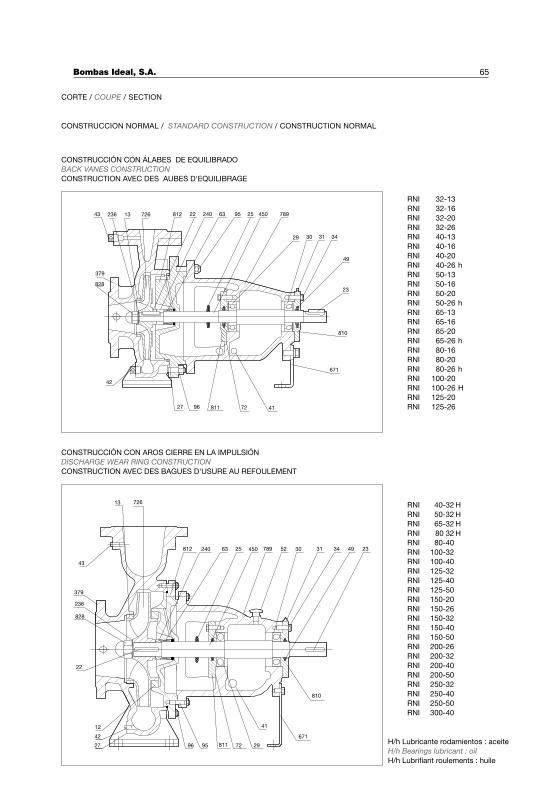
828
43 236 13 726 812 22 240 63 25 450 789
30 31
49
23
810
671
417227
379
811
29
42
95
96
34
27
12
42
828
379
236
43
13 726
671
7296 81195 29
41
810
22
812 63240 78945025 52 30 3431 49 23
65
H/h Lubricante rodamientos : aceite
H/h Bearings lubricant : oil
H/h Lubrifiant roulements : huile
RNI 32-13
RNI 32-16
RNI 32-20
RNI 32-26
RNI 40-13
RNI 40-16
RNI 40-20
RNI 40-26 h
RNI 50-13
RNI 50-16
RNI 50-20
RNI 50-26 h
RNI 65-13
RNI 65-16
RNI 65-20
RNI 65-26 h
RNI 80-16
RNI 80-20
RNI 80-26 h
RNI 100-20
RNI 100-26 H
RNI 125-20
RNI 125-26
RNI 40-32 H
RNI 50-32 H
RNI 65-32 H
RNI 80 32 H
RNI 80-40
RNI 100-32
RNI 100-40
RNI 125-32
RNI 125-40
RNI 125-50
RNI 150-20
RNI 150-26
RNI 150-32
RNI 150-40
RNI 150-50
RNI 200-26
RNI 200-32
RNI 200-40
RNI 200-50
RNI 250-32
RNI 250-40
RNI 250-50
RNI 300-40
CORTE / COUPE / SECTION
CONSTRUCCION NORMAL / STANDARD CONSTRUCTION / CONSTRUCTION NORMAL
CONSTRUCCIÓN CON ÁLABES DE EQUILIBRADO
BACK VANES CONSTRUCTION
CONSTRUCTION AVEC DES AUBES D'EQUILIBRAGE
CONSTRUCCIÓN CON AROS CIERRE EN LA IMPULSIÓN
DISCHARGE WEAR RING CONSTRUCTION
CONSTRUCTION AVEC DES BAGUES D'USURE AU REFOULEMENT
Bombas Ideal, S.A.
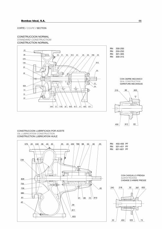
65366210
63812450
240 218 32 397 653
22 450 320 73
CON CASQUILLO PRENSA
SLEEVE PACKING
CHEMISE D'ARBRE PRESSE
CON CIERRE MECANICO
SEAL CONSTRUCTION
GARNITURE MECANIQUE
RN 200-200
RN 250-250
RN 301-305
RN 300-315
RN 450-400 PF
RN 501-451 PF
RN 651-601 PF
42
12
13
828
22
726
379
39
40
23
810
30789292581243
31
450418116533221827240
51 33 24
34
671
46
CONSTRUCCION NORMAL
STANDARD CONSTRUCTION
CONSTRUCTION NORMAL
5224022379 324039 9878945025 43 2330
735
42
81
380
726
828
653
29
811
41
236
81099 72
49
CONSTRUCCION LUBRIFICADA POR ACEITE
OIL LUBRICATION CONSTRUCTION
CONSTRUCTION LUBRICATION HUILE
66
CORTE / COUPE / SECTION
Bombas Ideal, S.A.
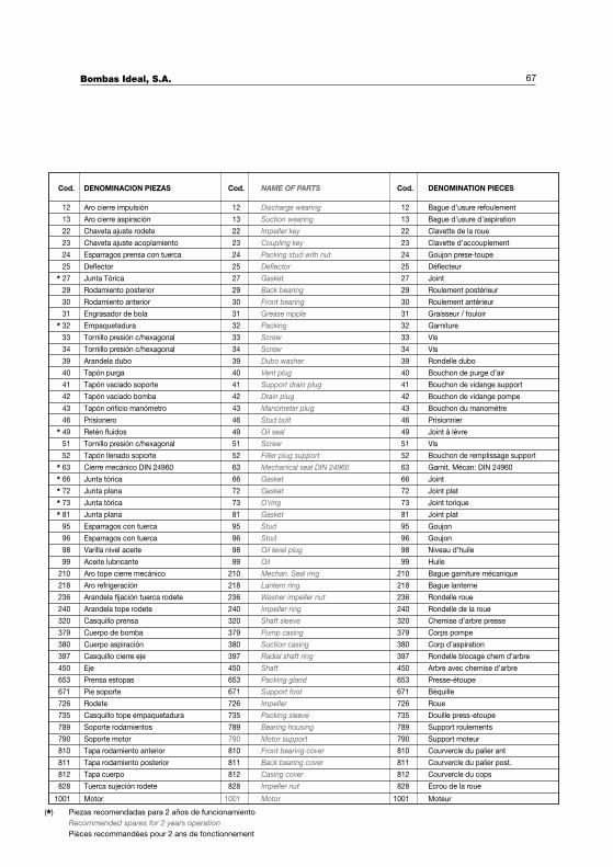
(*) Piezas recomendadas para 2 años de funcionamiento
Recommended spares for 2 years operation
Pièces recommandées pour 2 ans de fonctionnement
DENOMINACION PIEZAS DENOMINATION PIECESCod. Cod.Cod. NAME OF PARTS
Aro cierre impulsión Bague d’usure refoulement12 12 12Discharge wearing
Aro cierre aspiración Bague d’usure d’aspiration13 13 13Suction wearing
Chaveta ajuste rodete Clavette de la roue22 22 22Impeller key
Chaveta ajuste acoplamiento Clavette d’accouplement23 23 23Coupling key
Esparragos prensa con tuerca Goujon prese-toupe24 24 24Packing stud with nut
Deflector Déflecteur25 25 25Deflector
Junta Tórica Joint27 27 27Gasket
Rodamiento posterior Roulement postérieur29 29 29Back bearing
Rodamiento anterior Roulement antérieur30 30 30Front bearing
Engrasador de bola Graisseur / fouloir31 31 31Grease nipple
Empaquetadura Garniture32 32 32Packing
Tornillo presión c/hexagonal Vis33 33 33Screw
Tornillo presión c/hexagonal Vis34 34 34Screw
Arandela dubo Rondelle dubo39 39 39Dubo washer
Tapón purga Bouchon de purge d’air40 40 40Vent plug
Tapón vaciado soporte Bouchon de vidange support41 41 41Support drain plug
Tapón vaciado bomba Bouchon de vidange pompe42 42 42Drain plug
Tapón orificio manómetro Bouchon du manomètre43 43 43Manometer plug
Prisionero Prisionnier46 46 46Stud bolt
Retén fluidos Joint à lévre49 49 49Oil seal
Tornillo presión c/hexagonal Vis51 51 51Screw
Tapón llenado soporte Bouchon de remplissage support52 52 52Filler plug support
Cierre mecánico DIN 24960 Garnit. Mécan: DIN 2496063 63 63Mechanical seal DIN 24960
Junta tórica Joint66 66 66Gasket
Junta plana Joint plat72 72 72Gasket
Junta tórica Joint torique73 73 73O’ring
Junta plana Joint plat81 81 81Gasket
Esparragos con tuerca Goujon95 95 95Stud
Esparragos con tuerca Goujon96 96 96Stud
Varilla nivel aceite Niveau d’huile98 98 98Oil level plug
Aceite lubricante Huile99 99 99Oil
Aro tope cierre mecánico Bague garniture mécanique210 210 210Mechan. Seal ring
Aro refrigeración Bague lanterne218 218 218Lantern ring
Arandela fijación tuerca rodete Rondelle roue236 236 236Washer impeller nut
Arandela tope rodete Rondelle de la roue240 240 240Impeller ring
Casquillo prensa Chemise d’arbre presse320 320 320Shaft sleeve
Cuerpo de bomba Corps pompe379 379 379Pump casing
Cuerpo aspiración Corp d’aspiration380 380 380Suction casing
Casquillo cierre eje Rondelle blocage chem d’arbre397 397 397Radial shaft ring
Eje Arbre avec chemise d’arbre450 450 450Shaft
Prensa estopas Presse-étoupe653 653 653Packing gland
Pie soporte Béquille671 671 671Support foot
Rodete Roue726 726 726Impeller
Casquillo tope empaquetadura Douille press-etoupe735 735 735Packing sleeve
Soporte rodamientos Support roulements789 789 789Bearing housing
Soporte motor Support moteur790 790 790Motor support
Tapa rodamiento anterior Courvercle du palier ant810 810 810Front bearing cover
Tapa rodamiento posterior Courvercle du palier post.811 811 811Back bearing cover
Tapa cuerpo Courvercle du cops812 812 812Casing cover
Tuerca sujeción rodete Ecrou de la roue828 828 828Impeller nut
Motor Moteur1001 1001 1001Motor
*
*
*
*****
67Bombas Ideal, S.A.
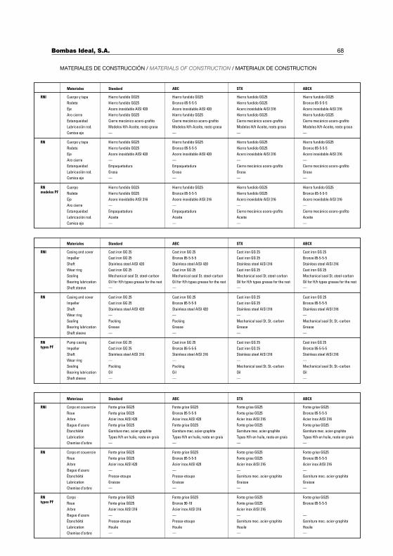
RNI
RN
RNtypes PF
Casing and cover
Materiales
Impeller
Shaft
Wear ring
Sealing
Bearing lubrication
Shaft steeve
Casing and cover
Impeller
Shaft
Wear ring
Sealing
Bearing lubrication
Shaft sleeve
Pump casing
Impeller
Shaft
Wear ring
Sealing
Bearing lubrication
Shaft sleeve
Standard
Cast iron GG 25
Cast iron GG 25
Stainless steel AISI 420
Cast iron GG 25
Mechanical seal St. steel-carbon
Oil for H/h types grease for the rest
—
Cast iron GG 25
Cast iron GG 25
Stainless steel AISI 420
—
Packing
Grease
—
Cast iron GG 25
Cast iron GG 25
Stainless steel AISI 316
—
Packing
Oil
—
Cast iron GG 25
ABC
Bronze 85-5-5-5
Stainless steel AISI 420
Cast iron GG 25
Mechanical seal St. steel-carbon
Oil for H/h types grease for the rest
—
Cast iron GG 25
Bronze 85-5-5-5
Stainless steel AISI 420
—
Packing
Grease
—
Cast iron GG 25
Bronze 85-5-5-5
Stainless steel AISI 316
—
Packing
Oil
—
STX
Cast iron GG 25
Cast iron GG 25
Stainless steel AISI 316
Cast iron GG 25
Mechanical seal St. steel-carbon
Oil for H/h types grease for the rest
—
Cast iron GG 25
Cast iron GG 25
Stainless steel AISI 316
—
Mechanical seal St. St.-carbon
Grease
—
Cast iron GG 25
Cast iron GG 25
Stainless steel AISI 316
—
Mechanical seal St. St.-carbon
Oil
—
ABCX
Cast iron GG 25
Bronze 85-5-5-5
Stainless steel AISI 316
Cast iron GG 25
Mechanical seal St. steel-carbon
Oil for H/h types grease for the rest
—
Cast iron GG 25
Bronze 85-5-5-5
Stainless steel AISI 316
—
Mechanical seal St. St.-carbon
Grease
—
Cast iron GG 25
Bronze 85-5-5-5
Stainless steel AISI 316
—
Mechanical seal St. St.-carbon
Oil
—
RNI
RN
RNtypes PF
Corps et couvercie
Materiaux
Roue
Arbre
Bague d’usure
Étanchéité
Lubrication
Chemise d’arbre
Corps et couvercie
Roue
Arbre
Bague d’usure
Étanchéité
Lubrication
Chemise d’arbre
Corps
Roue
Arbre
Bague d’usure
Étanchéité
Lubrication
Chemise d’arbre
Fonte grise GG25
Standard
Fonte grise GG25
Acier inox AISI 420
Fonte grise GG25
Garniture mec. acier-graphite
Types H/h en huile, reste en grais
—
Fonte grise GG25
Fonte grise GG25
Acier inox AISI 420
—
Presse-etoupe
Graisse
—
Fonte grise GG25
Fonte grise GG25
Acier inox AISI 316
—
Presse-etoupe
Houile
—
Fonte grise GG25
ABC
Bronze 85-5-5-5
Acier inox AISI 420
Fonte grise GG25
Garniture mec. acier-graphite
Types H/h en huile, reste en grais
—
Fonte grise GG25
Bronze 85-5-5-5
Acier inox AISI 420
—
Presse-etoupe
Graisse
—
Fonte grise GG25
Bronze 90-10
Acier inox AISI 316
—
Presse-etoupe
Houile
—
Fonte grise GG25
STX
Fonte grise GG25
Acier inox AISI 316
Fonte grise GG25
Garniture mec. acier-graphite
Types H/h en huile, reste en grais
—
Fonte grise GG25
Fonte grise GG25
Acier inox AISI 316
—
Garniture mec. acier-graphite
Graisse
—
Fonte grise GG25
Fonte grise GG25
Acier inox AISI 316
—
Garniture mec. acier-graphite
Houile
—
Fonte grise GG25
ABCX
Bronze 85-5-5-5
Acier inox AISI 316
Fonte grise GG25
Garniture mec. acier-graphite
Types H/h en huile, reste en grais
—
Fonte grise GG25
Bronze 85-5-5-5
Acier inox AISI 316
—
Garniture mec. acier-graphite
Graisse
—
Fonte grise GG25
Bronze 85-5-5-5
—
Garniture mec. acier-graphite
Houile
—
RNI
RN
RNmodelos PF
Cuerpo y tapa
Camisa eje
Materiales
Rodete
Eje
Aro cierre
Estanqueidad
Lubricación rod.
Camisa eje
Cuerpo y tapa
Rodete
Eje
Aro cierre
Estanqueidad
Lubricación rod.
Camisa eje
Cuerpo
Rodete
Eje
Aro cierre
Estanqueidad
Lubricación rod.
Hierro fundido GG25
Cierre mecánico acero-grafito
Modelos H/h Aceite, resto grasa
—
Standard
Hierro fundido GG25
Acero inoxidable AISI 420
Hierro fundido GG25
—
Hierro fundido GG25
Hierro fundido GG25
Acero inoxidable AISI 420
—
Empaquetadura
Grasa
—
Hierro fundido GG25
Hierro fundido GG25
Acero inoxidable AISI 316
—
Empaquetadura
Aceite
Hierro fundido GG25
—
ABC
Bronce 85-5-5-5
Acero inoxidable AISI 420
Hierro fundido GG25
Cierre mecánico acero-grafito
Modelos H/h Aceite, resto grasa
—
Hierro fundido GG25
Bronce 85-5-5-5
Acero inoxidable AISI 420
—
Empaquetadura
Grasa
—
Hierro fundido GG25
Bronce 85-5-5-5
Acero inoxidable AISI 316
—
Empaquetadura
Aceite
—
Hierro fundido GG25
STX
Hierro fundido GG25
Acero inoxidable AISI 316
Hierro fundido GG25
Cierre mecánico acero-grafito
Modelos H/h Aceite, resto grasa
—
Hierro fundido GG25
Hierro fundido GG25
Acero inoxidable AISI 316
—
Cierre mecánico acero-grafito
Grasa
—
Hierro fundido GG25
Hierro fundido GG25
Acero inoxidable AISI 316
—
Cierre mecánico acero-grafito
Aceite
Hierro fundido GG25
—
ABCX
Bronce 85-5-5-5
Acero inoxidable AISI 316
Hierro fundido GG25
Cierre mecánico acero-grafito
Modelos H/h Aceite, resto grasa
—
Hierro fundido GG25
Bronce 85-5-5-5
Acero inoxidable AISI 316
—
Cierre mecánico acero-grafito
Grasa
—
Hierro fundido GG25
Bronce 85-5-5-5
Acero inoxidable AISI 316
—
Cierre mecánico acero-grafito
Aceite
68
MATERIALES DE CONSTRUCCIÓN / MATERIALS OF CONSTRUCTION / MATERIAUX DE CONSTRUCTION
Bombas Ideal, S.A.

NOTAS / NOTES

NOTAS / NOTES
DECLARACION DE CONFORMIDAD CEE
BOMBAS IDEAL S.A., con domicilio en Massalfassar, Polígono Industrial del Mediterráneo, calle Cid Nº 8,
declara que todas las bombas RN y RNI, servidas con motor incorporado, son conformes con las Directivas
Europeas:� 98/37/CEE y sucesivas modificaciones. Seguridad en máquinas.� 89/336/CEE Compatibilidad electromagnética.� 73/23/CEE. Material eléctrico destinado a utilizarse con límites de tensión.
Normas armonizadas empleadas para la determinación de conformidad:
EN 292/1-2, EN 60335-1, EN 60335-2-41, EN 55014-1,.y EN 55014-2
Las bombas suministradas en eje libre cumplen con todas las normativas de seguridad, pero no deben ponerse
en marcha ni marcarse CE, hasta que la máquina donde estén instaladas sea declarada conforme con las
Directivas pertinentes.
DECLARATION OF CONFORMITY CE
BOMBAS IDEAL S.A., with address in Massalfassar, Polígono Industrial del Mediterráneo, Calle Cid Nº 8,
declares that all pumps RN and RNI, supplied with motor, conform the following European directives:� 98/37/CEE and modifications. Machinery safety.� 89/336/CEE. Electromagnetic compatibility.� 73/23/CEE. Electrical equipment designed for use within certain voltage limits.
Armonized standards used to determine conformity:
EN 292/1-2, EN 60335-1, EN 60335-2-41, EN 55014-1, y EN 55014-2.
Pumps supplied in bare shaft fulfil all the CE safety requirements, but must not be runned nor labelled as CE,
until the machine where they are install is declared conform to the directives involved.
DECLARATION DE CONFORMITE CEE
BOMBAS IDEAL S.A., avec siège social sis Massalfassar, Polígono Industrial del Mediterráneo, Calle Cid Nº
8, déclare que toutes les pompes RN et RNI, fournies avec moteur incorporé sont conformes aux Directrices
Européennes.� 98/37/CEE et modifications successives. Securité des machines.� 89/36/CEE Compatibilité électro-magnétique.� 73/23/CEE Matérial électrique destiné à être utilisé avec les limitations de tension.
Normes armonisées employées pour la détermination de conformité : EN 292/1, EN 55014-1, et EN 55014-2.
Les pompes fournies en disposition arbre nu acomplissent toutes les normes de sécurité mais elles ne peuvent
pas être mise en marche ni porter la marque CE, jusqu’a ce que la machine où elles doivent être installées soit
conforme à la normative en vigueur.
Massalfassar 22/11/08
Bombas Ideal, S.A. 71

BOMBAS IDEAL, S.A.Polígono Industrial Mediterráneo. Calle Cid, 8
Tel.: 34 961 402 143 - 902 203 400 - FAX: 34 96 140 21 31Massalfassar - Valencia (Spain)
www.bombasideal.comBO
MB
AS
IDE
AL,
S.A
. se
rese
rva
el d
erec
ho d
e va
riar
dat
os y
dim
ensi
ones
de
este
cat
álog
o si
n p
revi
o av
iso
BO
MB
AS
IDE
AL,
S.A
. res
erve
d t
he r
ight
to
alte
r p
erfo
rman
ce, s
pec
ifica
tions
at
any
time
with
out
prio
r no
tice.
BO
MB
AS
IDE
AL,
S.A
. se
rese
rve
le d
roit
de
varie
r le
s re
nsei
gnem
ents
et
dim
entio
ns d
e ce
cat
alog
ue s
ans
pré
avis