FOCO-LUZ PARA PISCINA AR-20660 - Janelabe.com · 1 foco-luz para piscina ar-20660 spotlight for...
24
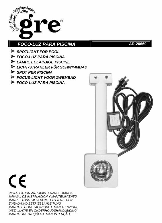
FOCO-LUZ PARA PISCINA AR-20660 SPOTLIGHT FOR POOL FOCO-LUZ PARA PISCINA LAMPE ECLAIRAGE PISCINE LICHT-STRAHLER FÜR SCHWIMMBAD SPOT PER PISCINA FOCUS-LICHT VOOR ZWEMBAD FOCO-LUZ PARA PISCINA INSTALLATION AND MAINTENANCE MANUAL MANUAL DE INSTALACIÓN Y MANTENIMIENTO MANUEL D’INSTALLATION ET D’ENTRETIEN EINBAU-UND BETRIEBSANLEITUNG MANUALE DI INSTALAZIONE E MANUTENZIONE INSTALLATIE-EN ONDERHOUDSHANDLEIDING MANUAL INSTRUÇÕES E MANUNTENÇÃO
Transcript of FOCO-LUZ PARA PISCINA AR-20660 - Janelabe.com · 1 foco-luz para piscina ar-20660 spotlight for...
1
FOCO-LUZ PARA PISCINA AR-20660
SPOTLIGHT FOR POOL FOCO-LUZ PARA PISCINA LAMPE ECLAIRAGE PISCINE LICHT-STRAHLER FÜR SCHWIMMBAD SPOT PER PISCINA FOCUS-LICHT VOOR ZWEMBAD FOCO-LUZ PARA PISCINA
INSTALLATION AND MAINTENANCE MANUAL MANUAL DE INSTALACIÓN Y MANTENIMIENTO MANUEL D’INSTALLATION ET D’ENTRETIEN EINBAU-UND BETRIEBSANLEITUNG MANUALE DI INSTALAZIONE E MANUTENZIONE INSTALLATIE-EN ONDERHOUDSHANDLEIDING MANUAL INSTRUÇÕES E MANUNTENÇÃO
2
ENGLISH
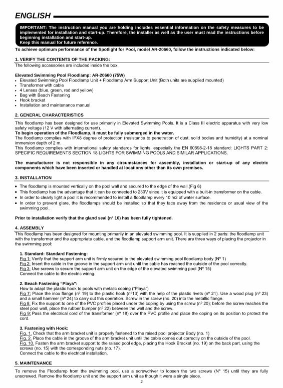
IMPORTANT: The instruction manual you are holding includes essential information on the safety measures to be implemented for installation and start-up. Therefore, the installer as well as the user must read the instructions before beginning installation and start-up. Keep this manual for future reference.
To achieve optimum performance of the Spotlight for Pool, model AR-20660, follow the instructions indicated below: 1. VERIFY THE CONTENTS OF THE PACKING: The following accessories are included inside the box: Elevated Swimming Pool Floodlamp: AR-20660 (75W) • Elevated Swimming Pool Floodlamp Unit + Floodlamp Arm Support Unit (Both units are supplied mounted) • Transformer with cable • 4 Lenses (blue, green, red and yellow) • Bag with Beach Fastening • Hook bracket • Installation and maintenance manual 2. GENERAL CHARACTERISTICS
This floodlamp has been designed for use primarily in Elevated Swimming Pools. It is a Class III electric apparatus with very low safety voltage (12 V with alternating current). To begin operation of the Floodlamp, it must be fully submerged in the water. The floodlamp complies with IPX8 degree of protection (resistance to penetration of dust, solid bodies and humidity) at a nominal immersion depth of 2 m. This floodlamp complies with international safety standards for lights, especially the EN 60598-2-18 standard: LIGHTS PART 2: SPECIFIC REQUIREMENTS SECTION 18 LIGHTS FOR SWIMMING POOLS AND SIMILAR APPLICATIONS. The manufacturer is not responsible in any circumstances for assembly, installation or start-up of any electric components which have been inserted or handled at locations other than its own premises. 3. INSTALLATION
• The floodlamp is mounted vertically on the pool wall and secured to the edge of the wall.(Fig 6) • This floodlamp has the advantage that it can be connected to 230V since it is equipped with a built-in transformer on the cable. • In order to clearly light a pool it is recommended to install a floodlamp every 10 m2 of water surface. • In order to prevent glare, the floodlamps should be installed so that they face away from the residence or usual view of the
swimming pool. Prior to installation verify that the gland seal (nº 10) has been fully tightened. 4. ASSEMBLY This floodlamp has been designed for mounting primarily in an elevated swimming pool. It is supplied in 2 parts: the floodlamp unit with the transformer and the appropriate cable, and the floodlamp support arm unit. There are three ways of placing the projector in the swimming pool:
1. Standard: Standard Fastening: Fig 1: Verify that the support arm unit is firmly secured to the elevated swimming pool floodlamp body (Nº 1) Fig 2: Insert the cable in the groove in the support arm unit until the cable has reached the outside of the pool correctly. Fig 3: Use screws to secure the support arm unit on the edge of the elevated swimming pool (Nº 15) Connect the cable to the electric wiring.
2. Beach Fastening “Playa”: How to adapt the plastic hook to pools with metalic coping (“Playa”) Fig 7: Place the inox flange (nº 19) to the plastic hook (nº13) with the help of the plastic rivets (nº 21). Use a wood plug (nº 23) and a small hammer (nº 24) to carry out this operation. Screw in the screw (no. 20) into the metallic flange. Fig 8: Fix the support to one of the PVC profiles placed under the coping by using the screw (nº 20); before the screw reaches the steel pool wall, place the rubber bumper (nº 22) between the wall and the screw. Fig 9: Pass the electrical cord of the transformer (nº 18) over the PVC profile and place the coping on its position to protect the cord.
3. Fastening with Hook: Fig. 1. Check that the arm bracket unit is properly fastened to the raised pool projector Body (no. 1) Fig. 2. Place the cable in the groove of the arm bracket unit until the cable comes out correctly on the outside of the pool. Fig. 10. Fasten the arm bracket support to the raised pool edge, placing the Hook Bracket (no. 19) on the back part, using the screws (no. 15) with the corresponding nuts (no. 17). Connect the cable to the electrical installation.
5. MAINTENANCE
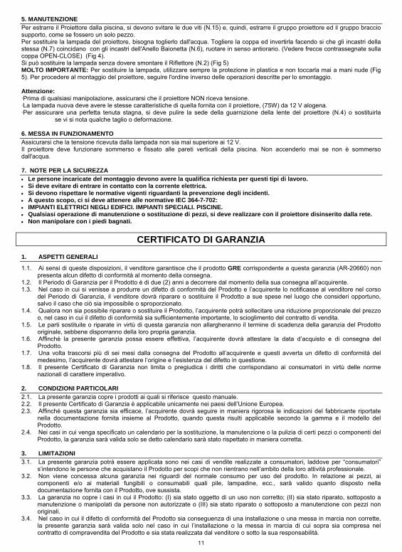
To remove the Floodlamp from the swimming pool, use a screwdriver to loosen the two screws (Nº 15) until they are fully unscrewed. Remove the floodlamp unit and the support arm unit as though it were a single piece.

3
To change the lamp of the floodlamp, first removed the unit from the water. Take off the decorative ring and invert it so that the insertion points on the Decorative Ring (Nº 7) match the insertion points on the Bayonet Ring (Nº 6). Turn counter-clockwise. (See the arrows on the decorative ring marked OPEN-CLOSE) (Fig 4). The lamp can be changed without dismounting the Reflector (Nº 2) (Fig 5) VERY IMPORTANT: To change the lamp, always use the plastic protector. Never touch the lamp with your bare hands (Fig 5). To mount the floodlamp, proceed in the opposite order of that described. Attention: • Before any handling ensure that there is NO voltage supplied to the floodlamp. • The new lamp should have the same characteristics as that supplied with the floodlamp (75W) 12 V halogen lamp. • In order to ensure full watertightness clean the seat of floodlamp lens joint (nº 4) or replace this if any permanent deformation or
notches are visible. 6. START-UP
Ensure that the voltage the lamp receives is never greater than 12 V. The floodlamp should only operate underwater while secured to the vertical walls of the pool. Never switch on the floodlamp if it is not underwater. 7. SAFETY WARNINGS
• The persons who are in charge of assembly should have the required qualifications for this type of work. • Avoid making contact with the electric voltage. • Comply with the current standards regarding accident prevention. • In this regard, the IEC 364-7-702 standards must be observed: • WIRING IN BUILDINGS. SPECIAL WIRING. SWIMMING POOLS. • Any operation related to the maintenance or replacement of parts should be performed with the floodlamp disconnected
from the electric power system. • Do not handle with wet feet.
GUARANTEE CERTIFICATE
1. GENERAL TERMS 1.1. In accordance with these provisions, the seller guarantees that the GRE product corresponding to this guarantee (“the
Product”) is in perfect condition at the time of delivery. 1.2. The Guarantee Term for the Product is two (2) years from the time it is delivered to the purchaser. 1.3. In the event of any defect in the Product that is notified by the purchaser to the seller during the Guarantee Term, the seller
will be obliged to repair or replace the Product, at his own cost and wherever he deems suitable, unless this is impossible or unreasonable.
1.4. If it is not possible to repair or replace the Product, the purchaser may ask for a proportional reduction in the price or, if the defect is sufficiently significant, the termination of the sales contract.
1.5. The replaced or repaired parts under this guarantee, will not extend the guarantee period of the original Product, but will have a separate guarantee.
1.6. In order for this guarantee to come into effect, the purchaser must provide proof of the date of purchase and delivery of the Product.
1.7. If, after six months from the delivery of the Product to the purchaser, he notifies a defect in the Product, the purchaser must provide proof of the origin and existence of the alleged defect.
1.8. This Guarantee Certificate is issued without prejudice to the rights corresponding to consumers under national regulations. 2. INDIVIDUAL TERMS 2.1. This guarantee covers the products referred to in this manual. 2.2. This Guarantee Certificate will only be applicable in European Union countries. 2.3. For this guarantee to be effective, the purchaser must strictly follow the Manufacturer’s instructions included in the
documentation provided with the Product, in cases where it is applicable according to the range and model of the Product. 2.4. When a time schedule is specified for the replacement, maintenance or cleaning of certain parts or components of the
Product, the guarantee will only be valid if this time schedule has been followed. 3. LIMITATIONS 3.1. This guarantee will only be applicable to sales made to consumers, understanding by “consumer”, a person who purchases
the Product for purposes not related to his professional activities. 3.2. The normal wear resulting from using the product is not guaranteed. With respect to expendable or consumable parts,
components and/or materials, such as batteries, light bulbs, etc. the stipulations in the documentation provided with the Product, will apply.
3.3. The guarantee does not cover those cases when the Product; (I) has been handled incorrectly; (II) has been repaired, serviced or handled by non-authorised people or (III) has been repaired or serviced not using original parts.
3.4. In cases where the defect of the Product is a result of incorrect installation or start-up, this guarantee will only apply when said installation or start-up is included in the sales contract of the Product and has been conducted by the seller or under his responsibility.
4
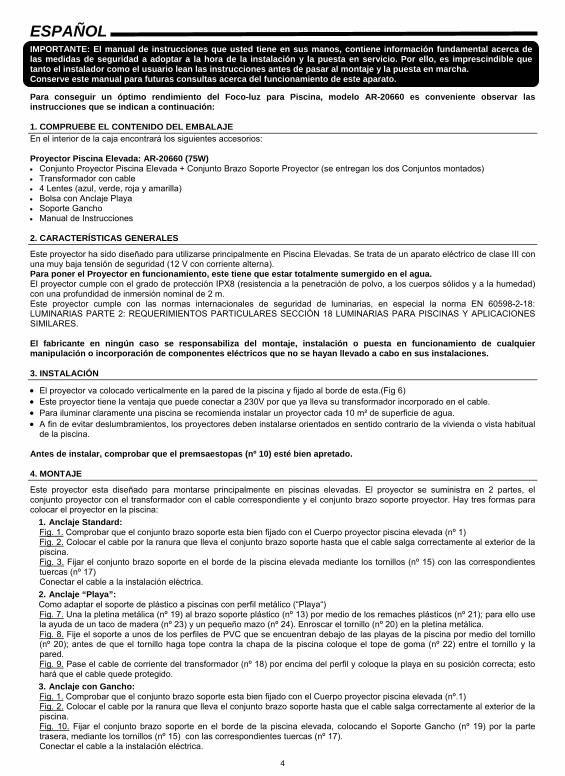
ESPAÑOL IMPORTANTE: El manual de instrucciones que usted tiene en sus manos, contiene información fundamental acerca de las medidas de seguridad a adoptar a la hora de la instalación y la puesta en servicio. Por ello, es imprescindible que tanto el instalador como el usuario lean las instrucciones antes de pasar al montaje y la puesta en marcha. Conserve este manual para futuras consultas acerca del funcionamiento de este aparato.
Para conseguir un óptimo rendimiento del Foco-luz para Piscina, modelo AR-20660 es conveniente observar las instrucciones que se indican a continuación: 1. COMPRUEBE EL CONTENIDO DEL EMBALAJE En el interior de la caja encontrará los siguientes accesorios: Proyector Piscina Elevada: AR-20660 (75W) • Conjunto Proyector Piscina Elevada + Conjunto Brazo Soporte Proyector (se entregan los dos Conjuntos montados) • Transformador con cable • 4 Lentes (azul, verde, roja y amarilla) • Bolsa con Anclaje Playa • Soporte Gancho • Manual de Instrucciones 2. CARACTERÍSTICAS GENERALES
Este proyector ha sido diseñado para utilizarse principalmente en Piscina Elevadas. Se trata de un aparato eléctrico de clase III con una muy baja tensión de seguridad (12 V con corriente alterna). Para poner el Proyector en funcionamiento, este tiene que estar totalmente sumergido en el agua. El proyector cumple con el grado de protección IPX8 (resistencia a la penetración de polvo, a los cuerpos sólidos y a la humedad) con una profundidad de inmersión nominal de 2 m. Este proyector cumple con las normas internacionales de seguridad de luminarias, en especial la norma EN 60598-2-18: LUMINARIAS PARTE 2: REQUERIMIENTOS PARTICULARES SECCIÓN 18 LUMINARIAS PARA PISCINAS Y APLICACIONES SIMILARES. El fabricante en ningún caso se responsabiliza del montaje, instalación o puesta en funcionamiento de cualquier manipulación o incorporación de componentes eléctricos que no se hayan llevado a cabo en sus instalaciones. 3. INSTALACIÓN
• El proyector va colocado verticalmente en la pared de la piscina y fijado al borde de esta.(Fig 6) • Este proyector tiene la ventaja que puede conectar a 230V por que ya lleva su transformador incorporado en el cable. • Para iluminar claramente una piscina se recomienda instalar un proyector cada 10 m² de superficie de agua. • A fin de evitar deslumbramientos, los proyectores deben instalarse orientados en sentido contrario de la vivienda o vista habitual
de la piscina. Antes de instalar, comprobar que el premsaestopas (nº 10) esté bien apretado. 4. MONTAJE
Este proyector esta diseñado para montarse principalmente en piscinas elevadas. El proyector se suministra en 2 partes, el conjunto proyector con el transformador con el cable correspondiente y el conjunto brazo soporte proyector. Hay tres formas para colocar el proyector en la piscina:
1. Anclaje Standard: Fig. 1. Comprobar que el conjunto brazo soporte esta bien fijado con el Cuerpo proyector piscina elevada (nº 1) Fig. 2. Colocar el cable por la ranura que lleva el conjunto brazo soporte hasta que el cable salga correctamente al exterior de la piscina. Fig. 3. Fijar el conjunto brazo soporte en el borde de la piscina elevada mediante los tornillos (nº 15) con las correspondientes tuercas (nº 17) Conectar el cable a la instalación eléctrica. 2. Anclaje “Playa”: Como adaptar el soporte de plástico a piscinas con perfil metálico (“Playa“) Fig. 7. Una la pletina metálica (nº 19) al brazo soporte plástico (nº 13) por medio de los remaches plásticos (nº 21); para ello use la ayuda de un taco de madera (nº 23) y un pequeño mazo (nº 24). Enroscar el tornillo (nº 20) en la pletina metálica. Fig. 8. Fije el soporte a unos de los perfiles de PVC que se encuentran debajo de las playas de la piscina por medio del tornillo (nº 20); antes de que el tornillo haga tope contra la chapa de la piscina coloque el tope de goma (nº 22) entre el tornillo y la pared. Fig. 9. Pase el cable de corriente del transformador (nº 18) por encima del perfil y coloque la playa en su posición correcta; esto hará que el cable quede protegido. 3. Anclaje con Gancho: Fig. 1. Comprobar que el conjunto brazo soporte esta bien fijado con el Cuerpo proyector piscina elevada (nº.1) Fig. 2. Colocar el cable por la ranura que lleva el conjunto brazo soporte hasta que el cable salga correctamente al exterior de la piscina. Fig. 10. Fijar el conjunto brazo soporte en el borde de la piscina elevada, colocando el Soporte Gancho (nº 19) por la parte trasera, mediante los tornillos (nº 15) con las correspondientes tuercas (nº 17). Conectar el cable a la instalación eléctrica.
5
5. MANTENIMIENTO
Para extraer el Proyector de la piscina se tienen que destornillar totalmente los dos tornillos (nº 15) con la ayuda de un destornillador y sacar el conjunto proyector y el conjunto brazo soporte, como si fueran una sola pieza. Para cambiar la lámpara del proyector, tenemos que sacar el proyector del agua. Quitar el embellecedor e invertirlo haciendo que los encajes del Embellecedor (nº 7) coincidan con los encajes del Anillo Bayoneta (nº 6), girar en el sentido anti-horario. (Ver flechas orientativas marcadas en el embellecedor OPEN-CLOSE) (Fig. 4). Se puede cambiar la lámpara sin tener que desmontar el Reflector (nº 2) (Fig. 5) MUY IMPORTANTE: Para cambiar la lámpara utilizar siempre el protector de plástico y no tocar nunca la lámpara con las manos desnudas (Fig 5). Para proceder al montaje del proyector, es de modo inverso al descrito. Atención: • Antes de cualquier manipulación asegurarse que el proyector NO recibe tensión. • La lámpara nueva debe reunir las mismas características que la suministrada con el proyector, (75W) de 12 V halógena. • Para asegurar una perfecta estanqueidad debe limpiarse el asiento de la junta lente proyector (nº 4) o bien sustituir esta si se
observa en ella alguna entalla o deformación permanente. 6. PUESTA EN MARCHA
Asegurarse que bajo ningún concepto la tensión que reciba la lámpara sea superior a 12 V. El proyector únicamente debe funcionar sumergido y fijado a las paredes verticales de la piscina. No encender nunca el proyector si no está sumergido en agua. 7. ADVERTENCIAS DE SEGURIDAD
• Las personas que se encarguen del montaje deben poseer la calificación requerida para este tipo de trabajos. • Se debe evitar entrar en contacto con la tensión eléctrica. • Se deben respetar las normas vigentes para la prevención de accidentes. • A tal respecto, se deben cumplir las normas IEC 364-7-702: • INSTALACIONES ELÉCTRICAS EN EDIFICIOS. INSTALACIONES ESPECIALES. PISCINAS. • Cualquier operación de mantenimiento o sustitución de piezas debe realizarse con el proyector desconectado de la red. • No manipular con los pies mojados.
CERTIFICADO DE GARANTÍA 1 ASPECTOS GENERALES 1.1 De acuerdo con estas disposiciones, el vendedor garantiza que el producto GRE correspondiente a esta garantía (AR-
20660) no presenta ninguna falta de conformidad en el momento de su entrega. 1.2 El Periodo de Garantía para el Producto es de dos (2) años y se calculará desde el momento de su entrega al comprador. 1.3 Si se produjera una falta de conformidad del Producto y el comprador lo notificase al vendedor durante el Periodo de
Garantía, el vendedor deberá reparar o sustituir el Producto a su propio coste en el lugar donde considere oportuno, salvo que ello sea imposible o desproporcionado.
1.4 Cuando no se pueda reparar o sustituir el Producto, el comprador podrá solicitar una reducción proporcional del precio o, si la falta de conformidad es suficientemente importante, la resolución del contrato de venta.
1.5 Las partes sustituidas o reparadas en virtud de esta garantía no ampliarán el plazo de la garantía del Producto original, si bien dispondrán de su propia garantía.
1.6 Para la efectividad de la presente garantía, el comprador deberá acreditar la fecha de adquisición y entrega del Producto. 1.7 Cuando hayan transcurrido más de seis meses desde la entrega del Producto al comprador y éste alegue falta de
conformidad de aquél, el comprador deberá acreditar el origen y la existencia del defecto alegado. 1.8 El presente Certificado de Garantía no limita o prejuzga los derechos que correspondan a los consumidores en virtud de
normas nacionales de carácter imperativo. 2 CONDICIONES PARTICULARES 2.1 La presente garantía cubre los productos a que hace referencia este manual. 2.2 El presente Certificado de Garantía será de aplicación únicamente en los países de la Unión Europea. 2.3 Para la eficacia de esta garantía, el comprador deberá seguir estrictamente las indicaciones del Fabricante incluidas en la
documentación que acompaña al Producto, cuando ésta resulte aplicable según la gama y modelo del Producto. 2.4 Cuando se especifique un calendario para la sustitución, mantenimiento o limpieza de ciertas piezas o componentes del
Producto, la garantía sólo será válida cuando se haya seguido dicho calendario correctamente. 3 LIMITACIONES 3.1 La presente garantía únicamente será de aplicación en aquellas ventas realizadas a consumidores, entendiéndose por
“consumidor”, aquella persona que adquiere el Producto con fines que no entran en el ámbito de su actividad profesional. 3.2 No se otorga ninguna garantía respecto del normal desgaste por uso del producto. En relación con las piezas, componentes
y/o materiales fungibles o consumibles como pilas, bombillas etc., se estará a lo dispuesto en la documentación que acompañe al Producto, en su caso.
3.3 La garantía no cubre aquellos casos en que el Producto: (I) haya sido objeto de un trato incorrecto; (II) haya sido reparado, mantenido o manipulado por persona no autorizada o (III) haya sido reparado o mantenido con piezas no originales.
3.4 Cuando la falta de conformidad del Producto sea consecuencia de una incorrecta instalación o puesta en marcha, la presente garantía sólo responderá cuando dicha instalación o puesta en marcha esté incluida en el contrato de compra-venta del Producto y haya sido realizada por el vendedor o bajo su responsabilidad.
6
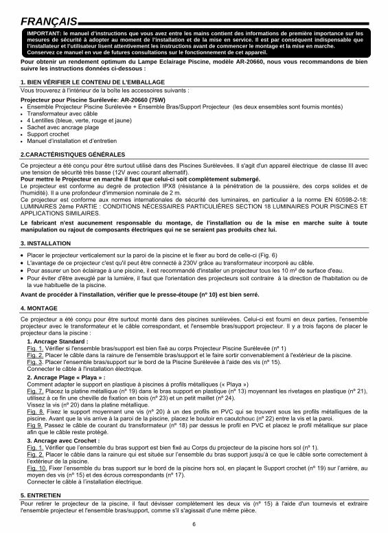
FRANÇAIS IMPORTANT: le manuel d’instructions que vous avez entre les mains contient des informations de première importance sur les mesures de sécurité à adopter au moment de l’installation et de la mise en service. Il est par conséquent indispensable que l’installateur et l’utilisateur lisent attentivement les instructions avant de commencer le montage et la mise en marche. Conservez ce manuel en vue de futures consultations sur le fonctionnement de cet appareil.
Pour obtenir un rendement optimum du Lampe Eclairage Piscine, modèle AR-20660, nous vous recommandons de bien suivre les instructions données ci-dessous : 1. BIEN VÉRIFIER LE CONTENU DE L'EMBALLAGE Vous trouverez à l'intérieur de la boîte les accessoires suivants : Projecteur pour Piscine Surélevée: AR-20660 (75W) • Ensemble Projecteur Piscine Surélevée + Ensemble Bras/Support Projecteur (les deux ensembles sont fournis montés) • Transformateur avec câble • 4 Lentilles (bleue, verte, rouge et jaune) • Sachet avec ancrage plage • Support crochet • Manuel d’installation et d’entretien 2.CARACTÉRISTIQUES GÉNÉRALES
Ce projecteur a été conçu pour être surtout utilisé dans des Piscines Surélevées. Il s'agit d'un appareil électrique de classe III avec une tension de sécurité très basse (12V avec courant alternatif). Pour mettre le Projecteur en marche il faut que celui-ci soit complètement submergé. Le projecteur est conforme au degré de protection IPX8 (résistance à la pénétration de la poussière, des corps solides et de l'humidité). Il a une profondeur d'immersion nominale de 2 m. Ce projecteur est conforme aux normes internationales de sécurité des luminaires, en particulier à la norme EN 60598-2-18: LUMINAIRES 2ème PARTIE : CONDITIONS NÉCESSAIRES PARTICULIÈRES SECTION 18 LUMINAIRES POUR PISCINES ET APPLICATIONS SIMILAIRES. Le fabricant n'est aucunement responsable du montage, de l'installation ou de la mise en marche suite à toute manipulation ou rajout de composants électriques qui ne se seraient pas produits chez lui. 3. INSTALLATION
• Placer le projecteur verticalement sur la paroi de la piscine et le fixer au bord de celle-ci (Fig. 6) • L'avantage de ce projecteur c'est qu'il peut être connecté à 230V grâce au transformateur incorporé au câble. • Pour assurer un bon éclairage à une piscine, il est recommandé d'installer un projecteur tous les 10 m² de surface d'eau. • Pour éviter d'être aveuglé par la lumière, il faut que l'orientation des projecteurs soit contraire à la direction de l'habitation ou de
la vue habituelle de la piscine. Avant de procéder à l'installation, vérifier que le presse-étoupe (nº 10) est bien serré. 4. MONTAGE
Ce projecteur a été conçu pour être surtout monté dans des piscines surélevées. Celui-ci est fourni en deux parties, l'ensemble projecteur avec le transformateur et le câble correspondant, et l'ensemble bras/support projecteur. Il y a trois façons de placer le projecteur dans la piscine :
1. Ancrage Standard : Fig. 1. Vérifier si l'ensemble bras/support est bien fixé au corps Projecteur Piscine Surélevée (nº 1) Fig. 2. Placer le câble dans la rainure de l'ensemble bras/support et le faire sortir convenablement à l'extérieur de la piscine. Fig. 3. Placer l'ensemble bras/support sur le bord de la Piscine Surélevée à l'aide des vis (nº 15). Connecter le câble à l'installation électrique. 2. Ancrage Plage « Playa » : Comment adapter le support en plastique à piscines à profils métalliques (« Playa ») Fig. 7. Placez la platine métallique (nº 19) dans le bras support en plastique (nº 13) moyennant les rivetages en plastique (nº 21), utilisez à ce fin une cheville de fixation en bois (nº 23) et un petit maillet (nº 24). Vissez la vis (nº 20) dans la platine métallique. Fig. 8. Fixez le support moyennant une vis (nº 20) à un des profils en PVC qui se trouvent sous les profils métalliques de la piscine. Avant que la vis arrive à la paroi de la piscine, placez le boutoir en caoutchouc (nº 22) entre la vis et la paroi. Fig 9. Passez le câble de courant du transformateur (nº 18) par dessus le profil en PVC et placez le profil métallique sur place afin que le câble reste protégé. 3. Ancrage avec Crochet : Fig. 1. Vérifier que l’ensemble du bras support est bien fixé au Corps du projecteur de la piscine hors sol (nº 1). Fig. 2. Placer le câble dans la rainure qui est située sur l’ensemble du bras support jusqu’à ce que le câble sorte correctement à l’extérieur de la piscine. Fig. 10. Fixer l’ensemble du bras support sur le bord de la piscine hors sol, en plaçant le Support crochet (nº 19) sur l’arrière, au moyen des vis (nº 15) et des écrous correspondants (nº 17). Connecter le câble à l’installation électrique.
5. ENTRETIEN Pour retirer le projecteur de la piscine, il faut dévisser complètement les deux vis (nº 15) à l'aide d'un tournevis et extraire l'ensemble projecteur et l'ensemble bras/support, comme s'il s'agissait d'une même pièce.
7
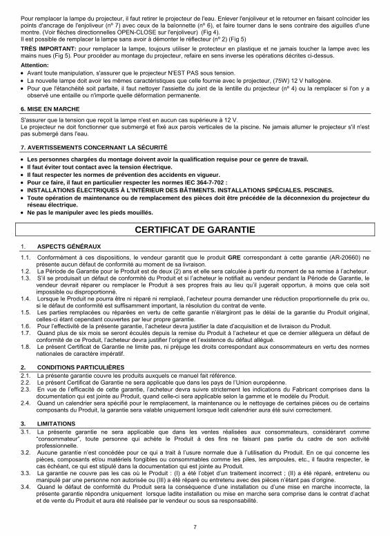
Pour remplacer la lampe du projecteur, il faut retirer le projecteur de l'eau. Enlever l'enjoliveur et le retourner en faisant coïncider les points d'ancrage de l'enjoliveur (nº 7) avec ceux de la baïonnette (nº 6), et faire tourner dans le sens contraire des aiguilles d'une montre. (Voir flèches directionnelles OPEN-CLOSE sur l'enjoliveur) (Fig 4). Il est possible de remplacer la lampe sans avoir à démonter le réflecteur (nº 2) (Fig 5) TRÈS IMPORTANT: pour remplacer la lampe, toujours utiliser le protecteur en plastique et ne jamais toucher la lampe avec les mains nues (Fig 5). Pour procéder au montage du projecteur, refaire en sens inverse les opérations décrites ci-dessus. Attention: • Avant toute manipulation, s'assurer que le projecteur N'EST PAS sous tension. • La nouvelle lampe doit avoir les mêmes caractéristiques que celle fournie avec le projecteur, (75W) 12 V hallogène. • Pour que l'étanchéité soit parfaite, il faut nettoyer l'assiette du joint de la lentille du projecteur (nº 4) ou la remplacer si l'on y a
observé une entaille ou n'importe quelle déformation permanente. 6. MISE EN MARCHE
S'assurer que la tension que reçoit la lampe n'est en aucun cas supérieure à 12 V. Le projecteur ne doit fonctionner que submergé et fixé aux parois verticales de la piscine. Ne jamais allumer le projecteur s'il n'est pas submergé dans l'eau. 7. AVERTISSEMENTS CONCERNANT LA SÉCURITÉ
• Les personnes chargées du montage doivent avoir la qualification requise pour ce genre de travail. • Il faut éviter tout contact avec la tension électrique. • Il faut respecter les normes de prévention des accidents en vigueur. • Pour ce faire, il faut en particulier respecter les normes IEC 364-7-702 : • INSTALLATIONS ÉLECTRIQUES À L'INTÉRIEUR DES BÂTIMENTS. INSTALLATIONS SPÉCIALES. PISCINES. • Toute opération de maintenance ou de remplacement des pièces doit être précédée de la déconnexion du projecteur du
réseau électrique. • Ne pas le manipuler avec les pieds mouillés.
CERTIFICAT DE GARANTIE 1. ASPECTS GÉNÉRAUX
1.1. Conformément à ces disposiitions, le vendeur garantit que le produit GRE correspondant à cette garantie (AR-20660) ne présente aucun défaut de conformité au moment de sa livraison.
1.2. La Période de Garantie pour le Produit est de deux (2) ans et elle sera calculée à partir du moment de sa remise à l’acheteur. 1.3. S’il se produisait un défaut de conformité du Produit et si l’acheteur le notifiait au vendeur pendant la Période de Garantie, le
vendeur devrait réparer ou remplacer le Produit à ses propres frais au lieu qu’il jugerait opportun, à moins que cela soit impossible ou disproportionné.
1.4. Lorsque le Produit ne pourra être ni réparé ni remplacé, l’acheteur pourra demander une réduction proportionnelle du prix ou, si le défaut de conformité est suffisamment important, la résolution du contrat de vente.
1.5. Les parties remplacées ou réparées en vertu de cette garantie n’élargiront pas le délai de la garantie du Produit original, celles-ci étant cependant couvertes par leur propre garantie.
1.6. Pour l’effectivité de la présente garantie, l’acheteur devra justifier la date d’acquisition et de livraison du Produit. 1.7. Quand plus de six mois se seront écoulés depuis la remise du Produit à l’acheteur et que ce dernier alléguera un défaut de
conformité de ce Produit, l’acheteur devra justifier l’origine et l’existence du défaut allégué. 1.8. Le présent Certificat de Garantie ne limite pas, ni préjuge les droits correspondant aux consommateurs en vertu des normes
nationales de caractère impératif. 2. CONDITIONS PARTICULIÈRES 2.1. La présente garantie couvre les produits auxquels ce manuel fait référence. 2.2. Le présent Certificat de Garantie ne sera applicable que dans les pays de l’Union européenne. 2.3. En vue de l’efficacité de cette garantie, l’acheteur devra suivre strictement les indications du Fabricant comprises dans la
documentation qui est jointe au Produit, quand celle-ci sera applicable selon la gamme et le modèle du Produit. 2.4. Quand un calendrier sera spécifié pour le remplacement, la maintenance ou le nettoyage de certaines pièces ou de certains
composants du Produit, la garantie sera valable uniquement lorsque ledit calendrier aura été suivi correctement. 3. LIMITATIONS 3.1. La présente garantie ne sera applicable que dans les ventes réalisées aux consommateurs, considéranrt comme
“consommateur”, toute personne qui achète le Produit à des fins ne faisant pas partie du cadre de son activité professionnelle.
3.2. Aucune garantie n’est concédée pour ce qui a trait à l’usure normale due à l’utilisation du Produit. En ce qui concerne les pièces, composants et/ou matériels fongibles ou consommables comme les piles, les ampoules, etc., il faudra respecter, le cas échéant, ce qui est stipulé dans la documentation qui est jointe au Produit.
3.3. La garantie ne couvre pas les cas où le Produit : (I) a été l’objet d’un traitement incorrect ; (II) a été réparé, entretenu ou manipulé par une personne non autorisée ou (III) a été réparé ou entretenu avec des pièces n’étant pas d’origine.
3.4. Quand le défaut de conformité du Produit sera la conséquence d’une installation ou d’une mise en marche incorrecte, la présente garantie répondra uniquement lorsque ladite installation ou mise en marche sera comprise dans le contrat d’achat et de vente du Produit et aura été réalisée par le vendeur ou sous sa responsabilité.
8
DEUTSCH WICHTIG: Das Handbuch mit den Betriebsanleitungen, das Sie in Händen halten, enthält wichtige Information über die anzuwendenden Sicherheitsmaßnahmen für die Installation und Inbetriebnahme. Es ist daher unerläßlich, daß die Anweisungen vom Installateur und vom Benutzer vor der Montage und Inbetriebnahme aufmerksam durchgelesen werden. Bewahren Sie dieses Handbuch auf, falls Sie zu einem späteren Zeitpunkt Informationen über die Funktion dieses Apparates nachschlagen möchten.
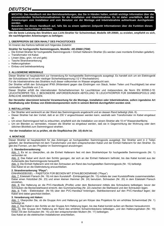
Um die beste Leistung des Strahlers aus Licht-Strahler für Schwimmbad, Modelle AR-20660, zu erzielen, empfiehlt es sich, die nachfolgenden Anweisungen zu befolgen: 1. ÜBERPRÜFEN SIE DEN INHALT DES PACKSTÜCKES Im Inneren des Kartons befindet sich folgendes Zubehör: Strahler für hochgestellte Swimmingpools, Modelle: AR-20660 (75W) • Die Einheit Strahler für hochgestellte Swimmingpools + Einheit Halterarm Strahler (Es werden zwei montierte Einheiten geliefert). • Transformator mit Kabel. • Linsen (blau, grün, rot und gelb) • Tasche Strandverankerung • Halterungshaken • Einbau-und betriebsanleitung 2. ALLGEMEINE MERKMALE Dieser Strahler ist hauptsächlich zur Verwendung für hochgestellte Swimmingpools ausgelegt. Es handelt sich um ein Elektrogerät der Schutzklasse III mit sehr niedriger Sicherheitsspannung (12 V Wechselstrom) Für die Inbetriebnahme des Strahlers muß dieser vollkommen im Wasser eingetaucht sein. Der Strahler erfüllt den Schutzgrad IPX8 (Widerstand gegen das Eindringen von Staub, festen Teilen und Feuchtigkeit) bei einer nominellen Tauchtiefe von 2 m. Dieser Strahler erfüllt die internationalen Sicherheitsnormen für Leuchtkörper und insbesondere die Norm EN 60598-2-18: LEUCHTKÖRPER TEIL 2: BESONDERE ANFORDERUNGEN ABTEILUNG 18 LEUCHTKÖRPER FÜR SWIMMINGPOOLS UND ÄHNLICHE ANWENDUNGEN. Der Hersteller übernimmt keinerlei Verantwortung für die Montage, Installation oder Inbetriebnahme, sofern irgendeine Art Handhabung oder Einbau von Elektrokomponenten nicht in seinem Betrieb durchgeführt worden sind. 3. INSTALLATION • Der Strahler wird senkrecht an der Wand des Swimmingpools angebracht und an dessen Rand befestigt (Abb. 6). • Dieser Strahler hat den Vorteil, daß er an 230 V angeschlossen werden kann, weshalb sein Transformator im Kabel eingebaut
ist. • Um einen Swimmingpool hell zu erleuchten, empfiehlt sich die Installation von einem Strahler alle 10 m² Wasseroberfläche. • Um ein Blenden zu vermeiden, müssen die Strahler so eingebaut werden, daß sie in Gegenrichtung der Wohnung oder dem
üblichen Blickfeld zum Swimmingpool strahlen. Vor der Installation ist zu prüfen, ob die Stopfbüchse (Nr. 10) dicht ist. 4. MONTAGE Dieser Strahler ist hauptsächlich für das Anbringen an hochgestellten Swimmingpools ausgelegt. Der Strahler wird in 2 Teilen geliefert, der Strahlereinheit mit dem Transformator und dem entsprechenden Kabel und der Einheit Halterarm für den Strahler. Es gibt drei Formen, um den Projektor im Swimmingpool anzubringen:
1. Standardverankerung: Abb. 1: Es ist zu überprüfen, ob die Einheit Halterarm fest mit dem Strahlerkörper für hochgestellte Swimmingpools (Nr. 1) verbunden ist. Abb. 2: Das Kabel wird durch den Schlitz gezogen, der sich an der Einheit Halterarm befindet, bis das Kabel korrekt aus der Außenseite des Swimmingpools heraustritt. Abb. 3: Die Einheit Halterarm wird mit den Schrauben am Rand des hochgestellten Swimmingpools (Nr. 15) befestigt. Das Kabel ist an die Elektroleitung anzuschließen. 2. Strandverankerung “Playa”: EINHÄNGEBÜGEL – PAβSTÜCK FÜR BECKEN MIT STAHLBECKENRAND (“Playa”) Abb. 7: Edelstahl Flansch (Nr. 19) mit dem Kunststoff - Einhängebügel (Nr. 13) mittels der zwei Kunststoffniete zusammenstellen. Dabei einen Holzdübel (Nr. 23) und einen kleinen Hammer (Nr. 24) benutzen. Schrauben (Nr. 20) in dem Edelstahl Flansch einziehen. Abb. 8: Die Halterung an die PVC-Handläufe (Profile) unter dem Beckenrand mittels des Schraubens befestigen; bevor der Schrauben die Beckenstahlwand erreicht, den Gummianschlag (Nr. 22) zwischen die Stahlwand und den Schrauben legen. Abb. 9: Trafo - Elektrokabel (Nr.18) über den PVC-Handlauf hinbringen. Stahlbeckenrand auf den PVC-Handlauf legen; der Kabel wird dabei geschützt bleiben. 3. Verankerung mit Haken: Abb. 1. Überprüfen Sie, ob die Gruppe Arm und Halterung gut am Körper des Projektors für ein erhöhtes Schwimmbad (Nr. 1) befestigt ist. Abb. 2. Das Kabel in den Schlitz an der Gruppe Arm Halterung legen, bis das Kabel korrekt außen am Becken herauskommt. Abb. 10. Die Gruppe Arm Halterung am Rand des erhöhten Schwimmbeckens befestigen, und den Halterungshaken (Nr. 19) hinten mit den Schrauben (Nr. 15) und den entsprechenden Muttern (Nr. 17) befestigen. Das Kabel an die elektrischen Installationen anschließen.
9
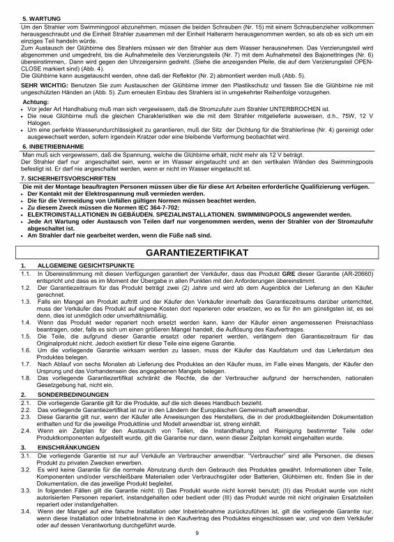
5. WARTUNG Um den Strahler vom Swimmingpool abzunehmen, müssen die beiden Schrauben (Nr. 15) mit einem Schraubenzieher vollkommen herausgeschraubt und die Einheit Strahler zusammen mit der Einheit Halterarm herausgenommen werden, so als ob es sich um ein einziges Teil handeln würde. Zum Austausch der Glühbirne des Strahlers müssen wir den Strahler aus dem Wasser herausnehmen. Das Verzierungsteil wird abgenommen und umgedreht, bis die Aufnahmeteile des Verzierungsteils (Nr. 7) mit dem Aufnahmeteil des Bajonettringes (Nr. 6) übereinstimmen,. Dann wird gegen den Uhrzeigersinn gedreht. (Siehe die anzeigenden Pfeile, die auf dem Verzierungsteil OPEN-CLOSE markiert sind) (Abb. 4). Die Glühbirne kann ausgetauscht werden, ohne daß der Reflektor (Nr. 2) abmontiert werden muß (Abb. 5). SEHR WICHTIG: Benutzen Sie zum Austauschen der Glühbirne immer den Plastikschutz und fassen Sie die Glühbirne nie mit ungeschützten Händen an (Abb. 5). Zum erneuten Einbau des Strahlers ist in umgekehrter Reihenfolge vorzugehen. Achtung: • Vor jeder Art Handhabung muß man sich vergewissern, daß die Stromzufuhr zum Strahler UNTERBROCHEN ist. • Die neue Glühbirne muß die gleichen Charakteristiken wie die mit dem Strahler mitgelieferte ausweisen, d.h., 75W, 12 V
Halogen. • Um eine perfekte Wasserundurchlässigkeit zu garantieren, muß der Sitz der Dichtung für die Strahlerlinse (Nr. 4) gereinigt oder
ausgewechselt werden, sofern irgendein Kratzer oder eine bleibende Verformung beobachtet wird. 6. INBETRIEBNAHME Man muß sich vergewissern, daß die Spannung, welche die Glühbirne erhält, nicht mehr als 12 V beträgt. Der Strahler darf nur angeschaltet sein, wenn er im Wasser eingetaucht und an den vertikalen Wänden des Swimmingpools befestigt ist. Er darf nie angeschaltet werden, wenn er nicht im Wasser eingetaucht ist. 7. SICHERHEITSVORSCHRIFTEN Die mit der Montage beauftragten Personen müssen über die für diese Art Arbeiten erforderliche Qualifizierung verfügen. • Der Kontakt mit der Elektrospannung muß vermieden werden. • Die für die Vermeidung von Unfällen gültigen Normen müssen beachtet werden. • Zu diesem Zweck müssen die Normen IEC 364-7-702: • ELEKTROINSTALLATIONEN IN GEBÄUDEN. SPEZIALINSTALLATIONEN. SWIMMINGPOOLS angewendet werden. • Jede Art Wartung oder Austausch von Teilen darf nur vorgenommen werden, wenn der Strahler von der Stromzufuhr
abgeschaltet ist. • Am Strahler darf nie gearbeitet werden, wenn die Füße naß sind.
GARANTIEZERTIFIKAT 1. ALLGEMEINE GESICHTSPUNKTE 1.1. In Übereinstimmung mit diesen Verfügungen garantiert der Verkäufer, dass das Produkt GRE dieser Garantie (AR-20660)
entspricht und dass es im Moment der Übergabe in allen Punkten mit den Anforderungen übereinstimmt. 1.2. Der Garantiezeitraum für das Produkt beträgt zwei (2) Jahre und wird ab dem Augenblick der Lieferung an den Käufer
gerechnet. 1.3. Falls ein Mangel am Produkt auftritt und der Käufer den Verkäufer innerhalb des Garantiezeitraums darüber unterrichtet,
muss der Verkäufer das Produkt auf eigene Kosten dort reparieren oder ersetzen, wo es für ihn am günstigsten ist, es sei denn, dies ist unmöglich oder unverhältnismäßig.
1.4. Wenn das Produkt weder repariert noch ersetzt werden kann, kann der Käufer einen angemessenen Preisnachlass beantragen, oder, falls es sich um einen größeren Mangel handelt, die Auflösung des Kaufvertrages.
1.5. Die Teile, die aufgrund dieser Garantie ersetzt oder repariert werden, verlängern den Garantiezeitraum für das Originalprodukt nicht. Jedoch existiert für diese Teile eine eigene Garantie.
1.6. Um die vorliegende Garantie wirksam werden zu lassen, muss der Käufer das Kaufdatum und das Lieferdatum des Produktes belegen.
1.7. Nach Ablauf von sechs Monaten ab Lieferung des Produktes an den Käufer muss, im Falle eines Mangels, der Käufer den Ursprung und das Vorhandensein des angegebenen Mangels belegen.
1.8. Das vorliegende Garantiezertifikat schränkt die Rechte, die der Verbraucher aufgrund der herrschenden, nationalen Gesetzgebung hat, nicht ein.
2. SONDERBEDINGUNGEN 2.1. Die vorliegende Garantie gilt für die Produkte, auf die sich dieses Handbuch bezieht. 2.2. Das vorliegende Garantiezertifikat ist nur in den Ländern der Europäischen Gemeinschaft anwendbar. 2.3. Diese Garantie gilt nur, wenn der Käufer alle Anweisungen des Herstellers, die in der produktbegleitenden Dokumentation
enthalten und für die jeweilige Produktlinie und Modell anwendbar ist, streng einhält. 2.4. Wenn ein Zeitplan für den Austausch von Teilen, die Instandhaltung und Reinigung bestimmter Teile oder
Produktkomponenten aufgestellt wurde, gilt die Garantie nur dann, wenn dieser Zeitplan korrekt eingehalten wurde. 3. EINSCHRÄNKUNGEN 3.1. Die vorliegende Garantie ist nur auf Verkäufe an Verbraucher anwendbar. “Verbraucher” sind alle Personen, die dieses
Produkt zu privaten Zwecken erwerben. 3.2. Es wird keine Garantie für die normale Abnutzung durch den Gebrauch des Produktes gewährt. Informationen über Teile,
Komponenten und/oder verschleißbare Materialien oder Verbrauchsgüter oder Batterien, Glühbirnen etc. finden Sie in der Dokumentation, die das jeweilige Produkt begleitet.
3.3. In folgenden Fällen gilt die Garantie nicht: (I) Das Produkt wurde nicht korrekt benutzt; (II) das Produkt wurde von nicht autorisierten Personen repariert, instandgehalten oder bedient oder (III) das Produkt wurde mit nicht originalen Ersatzteilen repariert oder instandgehalten.
3.4. Wenn der Mangel auf eine falsche Installation oder Inbetriebnahme zurückzuführen ist, gilt die vorliegende Garantie nur, wenn diese Installation oder Inbetriebnahme in den Kaufvertrag des Produktes eingeschlossen war, und von dem Verkäufer oder auf dessen Verantwortung durchgeführt wurde.
10
ITALIANO
IMPORTANTE: Il manuale d’istruzioni in suo possesso contiene informazioni fondamentali sulle misure di sicurezza da adottare per l'installazione e la messa in servizio. Per ciò è imprescindibile che sia l’installatore che l’utente leggano le istruzioni prima di iniziare il montaggio e la messa in servizio. Conservi questo manuale per poter consultare in futuro in merito al funzionamento di questo apparecchio.
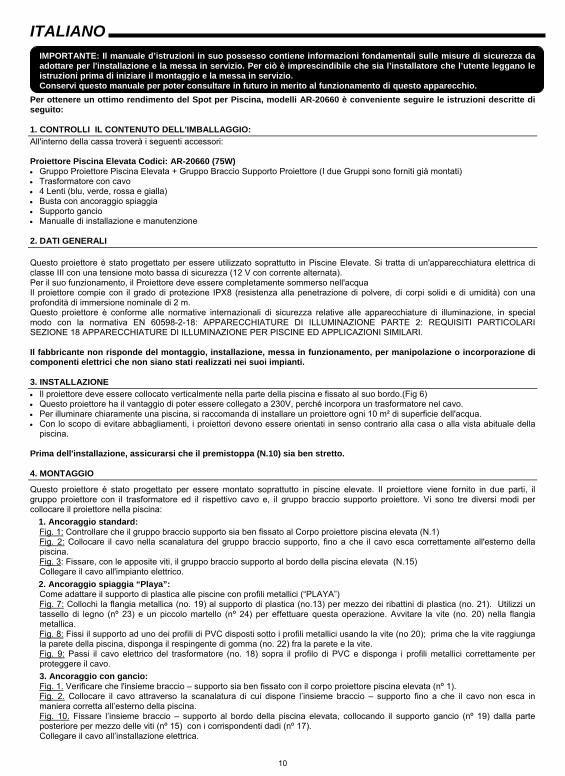
Per ottenere un ottimo rendimento del Spot per Piscina, modelli AR-20660 è conveniente seguire le istruzioni descritte di seguito: 1. CONTROLLI IL CONTENUTO DELL'IMBALLAGGIO: All'interno della cassa troverà i seguenti accessori: Proiettore Piscina Elevata Codici: AR-20660 (75W) • Gruppo Proiettore Piscina Elevata + Gruppo Braccio Supporto Proiettore (I due Gruppi sono forniti già montati) • Trasformatore con cavo • 4 Lenti (blu, verde, rossa e gialla) • Busta con ancoraggio spiaggia • Supporto gancio • Manualle di installazione e manutenzione 2. DATI GENERALI Questo proiettore è stato progettato per essere utilizzato soprattutto in Piscine Elevate. Si tratta di un'apparecchiatura elettrica di classe III con una tensione moto bassa di sicurezza (12 V con corrente alternata). Per il suo funzionamento, il Proiettore deve essere completamente sommerso nell'acqua Il proiettore compie con il grado di protezione IPX8 (resistenza alla penetrazione di polvere, di corpi solidi e di umidità) con una profondità di immersione nominale di 2 m. Questo proiettore è conforme alle normative internazionali di sicurezza relative alle apparecchiature di illuminazione, in special modo con la normativa EN 60598-2-18: APPARECCHIATURE DI ILLUMINAZIONE PARTE 2: REQUISITI PARTICOLARI SEZIONE 18 APPARECCHIATURE DI ILLUMINAZIONE PER PISCINE ED APPLICAZIONI SIMILARI. Il fabbricante non risponde del montaggio, installazione, messa in funzionamento, per manipolazione o incorporazione di componenti elettrici che non siano stati realizzati nei suoi impianti. 3. INSTALLAZIONE • Il proiettore deve essere collocato verticalmente nella parte della piscina e fissato al suo bordo.(Fig 6) • Questo proiettore ha il vantaggio di poter essere collegato a 230V, perché incorpora un trasformatore nel cavo. • Per illuminare chiaramente una piscina, si raccomanda di installare un proiettore ogni 10 m² di superficie dell'acqua. • Con lo scopo di evitare abbagliamenti, i proiettori devono essere orientati in senso contrario alla casa o alla vista abituale della
piscina. Prima dell'installazione, assicurarsi che il premistoppa (N.10) sia ben stretto. 4. MONTAGGIO
Questo proiettore è stato progettato per essere montato soprattutto in piscine elevate. Il proiettore viene fornito in due parti, il gruppo proiettore con il trasformatore ed il rispettivo cavo e, il gruppo braccio supporto proiettore. Vi sono tre diversi modi per collocare il proiettore nella piscina:
1. Ancoraggio standard: Fig. 1: Controllare che il gruppo braccio supporto sia ben fissato al Corpo proiettore piscina elevata (N.1) Fig. 2: Collocare il cavo nella scanalatura del gruppo braccio supporto, fino a che il cavo esca correttamente all'esterno della piscina. Fig. 3: Fissare, con le apposite viti, il gruppo braccio supporto al bordo della piscina elevata (N.15) Collegare il cavo all'impianto elettrico. 2. Ancoraggio spiaggia “Playa”: Come adattare il supporto di plastica alle piscine con profili metallici (“PLAYA”) Fig. 7: Collochi la flangia metallica (no. 19) al supporto di plastica (no.13) per mezzo dei ribattini di plastica (no. 21). Utilizzi un tassello di legno (nº 23) e un piccolo martello (nº 24) per effettuare questa operazione. Avvitare la vite (no. 20) nella flangia metallica. Fig. 8: Fissi il supporto ad uno dei profili di PVC disposti sotto i profili metallici usando la vite (no 20); prima che la vite raggiunga la parete della piscina, disponga il respingente di gomma (no. 22) fra la parete e la vite. Fig. 9: Passi il cavo elettrico del trasformatore (no. 18) sopra il profilo di PVC e disponga i profili metallici correttamente per proteggere il cavo. 3. Ancoraggio con gancio: Fig. 1. Verificare che l'insieme braccio – supporto sia ben fissato con il corpo proiettore piscina elevata (nº 1). Fig. 2. Collocare il cavo attraverso la scanalatura di cui dispone l’insieme braccio – supporto fino a che il cavo non esca in maniera corretta all’esterno della piscina. Fig. 10. Fissare l’insieme braccio – supporto al bordo della piscina elevata, collocando il supporto gancio (nº 19) dalla parte posteriore per mezzo delle viti (nº 15) con i corrispondenti dadi (nº 17). Collegare il cavo all’installazione elettrica.
11
5. MANUTENZIONE Per estrarre il Proiettore dalla piscina, si devono svitare le due viti (N.15) e, quindi, estrarre il gruppo proiettore ed il gruppo braccio supporto, come se fossero un solo pezzo. Per sostituire la lampada del proiettore, bisogna toglierlo dall'acqua. Togliere la coppa ed invertirla facendo si che gli incastri della stessa (N.7) coincidano con gli incastri dell'Anello Baionetta (N.6), ruotare in senso antiorario. (Vedere frecce contrassegnate sulla coppa OPEN-CLOSE) (Fig 4). Si può sostituire la lampada senza dovere smontare il Riflettore (N.2) (Fig 5) MOLTO IMPORTANTE: Per sostituire la lampada, utilizzare sempre la protezione in plastica e non toccarla mai a mani nude (Fig 5). Per procedere al montaggio del proiettore, seguire l'ordine inverso delle operazioni descritte per lo smontaggio. Attenzione: ·Prima di qualsiasi manipolazione, assicurarsi che il proiettore NON riceva tensione. ·La lampada nuova deve avere le stesse caratteristiche di quella fornita con il proiettore, (75W) da 12 V alogena. ·Per assicurare una perfetta tenuta stagna, si deve pulire la sede della guarnizione della lente del proiettore (N.4) o sostituirla se vi si nota qualche taglio o deformazione. 6. MESSA IN FUNZIONAMENTO Assicurarsi che la tensione ricevuta dalla lampada non sia mai superiore ai 12 V. Il proiettore deve funzionare sommerso e fissato alle pareti verticali della piscina. Non accenderlo mai se non è sommerso dall'acqua. 7. NOTE PER LA SICUREZZA • Le persone incaricate del montaggio devono avere la qualifica richiesta per questi tipi di lavoro. • Si deve evitare di entrare in contatto con la corrente elettrica. • Si devono rispettare le normative vigenti riguardanti la prevenzione degli incidenti. • A questo scopo, ci si deve attenere alle normative IEC 364-7-702: • IMPIANTI ELETTRICI NEGLI EDIFICI. IMPIANTI SPECIALI. PISCINE. • Qualsiasi operazione di manutenzione o sostituzione di pezzi, si deve realizzare con il proiettore disinserito dalla rete. • Non manipolare con i piedi bagnati.
CERTIFICATO DI GARANZIA 1. ASPETTI GENERALI
1.1. Ai sensi di queste disposizioni, il venditore garantisce che il prodotto GRE corrispondente a questa garanzia (AR-20660) non presenta alcun difetto di conformità al momento della consegna.
1.2. Il Periodo di Garanzia per il Prodotto è di due (2) anni a decorrere dal momento della sua consegna all’acquirente. 1.3. Nel caso in cui si venisse a produrre un difetto di conformità del Prodotto e l’acquirente lo notificasse al venditore nel corso
del Periodo di Garanzia, il venditore dovrà riparare o sostituire il Prodotto a sue spese nel luogo che consideri opportuno, salvo il caso che ciò sia impossibile o sproporzionato.
1.4. Qualora non sia possibile riparare o sostituire il Prodotto, l’acquirente potrà sollecitare una riduzione proporzionale del prezzo o, nel caso in cui il difetto di conformità sia sufficientemente importante, lo scioglimento del contratto di vendita.
1.5. Le parti sostituite o riparate in virtù di questa garanzia non allargheranno il termine di scadenza della garanzia del Prodotto originale, sebbene disporranno della loro propria garanzia.
1.6. Affinché la presente garanzia possa essere effettiva, l’acquirente dovrà attestare la data d’acquisto e di consegna del Prodotto.
1.7. Una volta trascorsi più di sei mesi dalla consegna del Prodotto all’acquirente e questi avverta un difetto di conformità del medesimo, l’acquirente dovrà attestare l’origine e l’esistenza del difetto in questione.
1.8. Il presente Certificato di Garanzia non limita o pregiudica i diritti che corrispondano ai consumatori in virtù delle norme nazionali di carattere imperativo.
2. CONDIZIONI PARTICOLARI 2.1. La presente garanzia copre i prodotti ai quali si riferisce questo manuale. 2.2. Il presente Certificato di Garanzia è applicabile unicamente nei paesi dell’Unione Europea. 2.3. Affinché questa garanzia sia efficace, l’acquirente dovrà seguire in maniera rigorosa le indicazioni del fabbricante riportate
nella documentazione fornita insieme al Prodotto, quando questa risulti applicabile secondo la gamma e il modello del Prodotto.
2.4. Nei casi in cui venga specificato un calendario per la sostituzione, la manutenzione o la pulizia di certi pezzi o componenti del Prodotto, la garanzia sarà valida solo se detto calendario sarà stato rispettato in maniera corretta.
3. LIMITAZIONI 3.1. La presente garanzia potrà essere applicata sono nei casi di vendite realizzate a consumatori, laddove per “consumatori”
s’intendono le persone che acquistano il Prodotto per scopi che non rientrano nell’ambito della loro attività professionale. 3.2. Non viene concessa alcuna garanzia nei riguardi del normale consumo per uso del prodotto. In relazione ai pezzi, ai
componenti e/o ai materiali fungibili o consumabili quali pile, lampadine, ecc., sarà valido quanto disposto nella documentazione fornita con il Prodotto, ove sussista.
3.3. La garanzia no copre i casi in cui il Prodotto: (I) sia stato oggetto di un uso non corretto; (II) sia stato riparato, sottoposto a manutenzione o manipolati da persone non autorizzate o (III) sia stato riparato o sottoposto a manutenzione con pezzi non originali.
3.4. Nel caso in cui il difetto di conformità del Prodotto sia conseguenza di una installazione o una messa in marcia non corrette, la presente garanzia sarà valida solo nel caso in cui l’installazione o la messa in marcia di cui sopra sia compresa nel contratto di compravendita del Prodotto e sia stata realizzata dal venditore o sotto la sua responsabilità.
12
NEDERLANDS BELANGRIJK: De handleiding met instructies die voor U ligt bevat fundamentele informatie omtrent de veiligheidsmaatregelen die in acht moeten worden genomen bij het installeren en de in werking stelling van dit produkt. Daarom is het absoluut noodzakelijk dat zowel de installateur als de gebruiker de instructies aandachtig lezen alvorens tot de montage en in werk stelling over te gaan. Aangeraden wordt om deze handleiding zorgvuldig te bewaren voor eventuele verdere raadpleging betreffende de werking van dit apparaat.
Teneinde een optimaal rendement te verkrijgen van deze Projector Model AR-20660 voor Plastic Losstaande Zwembaden (die niet in de grond geïnstalleerd zijn) is het belangrijk de volgende instructies in acht te nemen. 1. DE INHOUD VAN DE DOOS NAGAAN De doos bevat de volgende onderdelen : Projector voor Losstaande Zwembaden met de volgende Codes: AR-20660 (75W) • 1 Projector voor Losstaande Zwembaden + Steunarm (beide worden geheel gemonteerd geleverd). • Transformator met kabel • 4 Lenzen (blauw, groen, rood en geel) • Tas met strandverankering • Steunhaak • Installatie-en onderhoudshandleiding 2. ALGEMENE EIGENSCHAPPEN Deze projector is speciaal ontworpen voor gebruik in Losstaande Zwembaden. Het is een elektrisch apparaat klasse III met een zeer lage spanning (12V met wisselstroom) om veiligheid te garanderen. Wanneer de Projector un werking gesteld wordt, moet hij zich helemaal onder water bevinden. De projector voldoet aan de beveiligingsvoorwaarde IPX8 (weerstand tot het binnendringen van stof, vaste lichamen en tevens weerstand tot het binnendringen van vocht) en heeft een nominale onderdompelingsmogelijkheid tot een diepte van 2 meter. Deze projector voldoet aan de Internationale Veiligheidsnormen voor verlichting, en speciaal aan de eis EN 60598-2-18 : VERLICHTING DEEL 2 : BIJZONDERE EISEN ARTIKEL 18 VOOR VERLICHTING VAN ZWEMBADEN EN SOORTGELIJKE TOEPASSINGEN. 3. INSTALLATIE • De projector wordt verticaal op de wand van het zwembad geplaatst en aan de rand van het zwembad vastgemaakt (Afbeelding
6) • Deze projector heeft het voordeel dat hij op 230V aangesloten kan worden omdat de transformator in de kabel opgenomen is. • Teneinde het zwembad voldoende te belichten, wordt aangeraden om voor elke 10m2 wateroppervlakte 1 projector te installeren. • Teneinde verblinding door het licht te voorkomen, moet iedere projector in de tegenovergestelde richting van de woning of van
het gebruikelijke zicht op het zwembad vanuit de woning geïnstalleerd worden Alvorens met de installering te beginnen, moet men eerst nagaan of de pakkingbus (No. 10) goed aangedrukt is 4. MONTAGE Deze projector is speciaal ontworpen om voornamelijk in Losstaande Zwembaden aangebracht te worden. De projector wordt geleverd in 2 delen, de projector met de overeenkomstige transformator en kabel, en daarnaast de steunarm voor de projector. De projector kan op drie manieren in het zwembad aangebracht worden:
1. Standaard verankering: Afbeelding 1: Nagaan of de steunarm goed vastzit aan de projector voor Losstaande Zwembaden (No. 1) Afbeelding 2: De kabel in de opening van de steunarm steken totdat de kabel er op de juiste wijze aan de buitenkant van het zwembad weer uitkomt. Afbeelding 3: De steunarm nu op de rand van het losstaande zwembad vastzetten door middel van de schroeven (No. 15) De kabel op de elektrische installatie aansluiten. 2. Strandverankering “Playa”: Het aanpassen van de kunststof drager voor profielmetaal zwembaden Afbeelding 7: De metaalplaat (no. 19) vastmaken aan de plastic drager (no. 13) door middel van de plastic klinknagels (no. 21) met behulp van een houten plug (no. 23) en een kleine hamer (no. 24) De schroef (no. 20) in de metaalplaat schroeven. Afbeelding 8: De drager door middel van de schroef bevestigen aan één van de PVC profielen die zich onder de rand van het zwembad bevinden (voordat de schroef tegen het metaal aankomt gelieve een rubberstop (no. 22) er tussen te plaatsen). Afbeelding 9: Het snoer van de transformator (no. 18) op de rand plaatsen en de strip in zijn positie plaatsen voor bescherming. 3. Verankering met haak: Fig. 1. Controleer dat de steunarm goed aan de behuizing van de projector voor bovengronds zwembad bevestigd is (nº.1) Fig. 2. Steek de kabel in de gleuf van de steunarm totdat deze aan de buitenkant van het zwembad naar buiten komt. Fig. 10. Bevestig de steunarm aan de rand van het bovengrondse zwembad, bevestig daartoe de Steunhaak (nº 19) aan de achterzijde met behulp van de bouten (nº 15) en de bijbehorende moeren (nº 17). Verbind de kabel met de stroomvoorziening.
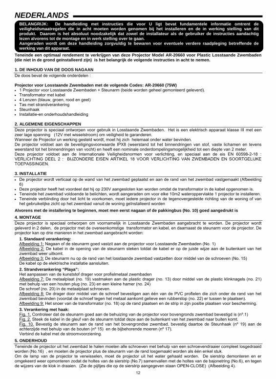
5. ONDERHOUD Teneinde de projector uit het zwembad te halen moeten alle schroeven met behulp van een schroevendraaier compleet losgedraaid worden (No.16) , en moeten de projector plus de steunarm van de rand losgemaakt worden als één enkel stuk. Om de lamp van de projector te verwisselen, moet de projector uit het water gehaald worden. De sierstrip demonteren en er omgekeerd weer opmonteren zodat de holtes van de sierstrip (No.7) samenvallen met de holtes van de bajonetring (No.6), en tegen de wijzers van de klok in draaien. (Zie de pijltjes die op de sierstrip aangegeven staan OPEN-CLOSE) (Afbeelding 4).
13
De lamp kan gewisseld worden zonder de reflector te hoeven demonteren (No.2) (Afbeelding 5). ZEER BELANGRIJK : Bij het verwisselen van de lamp moet er altijd een plastic bescherming gebruikt worden en de lamp mag nooit met de blote handen aangeraakt worden (Afbeelding 5). Om de projector weer opnieuw te monteren moet men omgekeerd te werk gaan zoals in deze paragraaf beschreven wordt. PAS OP : • Voordat men te werk gaat op welke manier ook, eerst nagaan of the projector GEEN stroom ontvangt. • De nieuwe lamp moet dezelfde eigenschappen hebben als de lamp die geleverd werd met de projector (75W) en 12V halogeen. • Om absoluut zeker te zijn van een hermetische sluiting moet het aansluitingsvlak van de koppeling tussen de lens en de projector
(No.4) schoongemaakt ofwel vervangen worden als er ook maar enige snee of een blijvende vervorming waargenomen worden. 6. IN WERKING STELLEN : Men moet zich er altijd van verzekeren dat de stroom die de lamp ontvangt onder geen enkele voorwaarde hoger dan 12V zal zijn. De projector mag alleen werken als hij zich totaal onder water bevindt en aan de vertikale wanden van het zwembad bevestigd is. Men mag de projector nooit aanzetten als hij niet geheel onder water is. 7. VEILIGHEIDSWAARSCHUWINGEN • Degenen die zich met de montage bezighouden, moeten de vereiste bevoeging hebben voor de uitvoering van dit soort
werkzaamheden. • Altijd ervoor zorgen om niet met de elektrische stroom in aanraking te komen. • De normen die gelden voor het vermijden van ongelukken moeten in acht genomen worden. • Daarvoor moet er voldaan worden aan de normen IEC 364-7-702 • ELEKTRISCHE INSTALLATIES IN GEBOUWEN . SPECIALE INSTALLATIES VOOR ZWEMBADEN • Iedere willekeurige handeling voor het onderhoud of de vervanging van de onderdelen mag alleen geschieden waneer
de projector niet op het net aangesloten is. • Nooit enige werkzaamheden uitoefenen op natte voeten.
GARANTIECERTIFIKAAT 1.1. ALGEMENE ASPEKTEN 1.2. In overeenkomst met de voorliggende bepalingen wordt door de verkoper gegarandeerd dat het produkt GRE verkocht onder
deze garantie (AR-20660) geen enkel defekt vertoont op het moment van levering. 1.3. De Garantieperiode voor het Produkt bedraagt twee (2) jaar en is geldig vanaf het moment dat het Produkt aan de koper
geleverd wordt. 1.4. Indien er zich een defekt aan het Produkt zou voordoen en de koper dit zou mededelen aan de verkoper gedurende de
geldige Garantieperiode, dan zal de verkoper het Produkt repareren of laten repareren op zijn eigen kosten alwaar de verkoper dit geschikt zou achten, behalve in het geval dat dit onmogelijk of buitensporig zou zijn.
1.5. Indien het Produkt niet gerepareerd of vervangen kan worden, dan kan de koper na verhouding prijsreduktie aanvragen, of, indien het defekt belangrijk genoeg is, de ontbinding van het verkoopcontract aanvragen.
1.6. Die delen van het Produkt die onder deze Garantie vervangen of gerepareerd zijn, kunnen de duur van de Garantieperiode voor het oorspronkelijke Produkt niet verlengen, maar zullen beschikken over een eigen garantie.
1.7. Voor de toepassing van deze garantie moet de koper de aankoopdatum en de levering van het Produkt kunnen aantonen. 1.8. Indien er meer dan zes maanden verlopen zijn sinds de levering van het Produkt aan de koper, en deze plotseling aangeeft
dat het Produkt niet aan de eisen voldoet, dan zal de koper de oorsprong en het bestaan van de volgens hem bestaande defekten moeten kunnen aantonen.
1.9. Dit Garantiecertifikaat beperkt of veroordeelt niet bij voorbaat de rechten die de gebruikers hebben en die gebaseerd zijn op nationale normen.
2. BIJZONDERE VOORWAARDEN 2.1. Deze garantie dekt de produkten waarnaar deze handleiding verwijst. 2.2. Het huidige Garantiecertifikaat is slechts van toepassing in landen van de Europese Unie. 2.3. Voor de toepassing van deze garantie en in geval deze garantie van toepassing is al naar gelang de serie en het model van
het Produkt, moet de koper de aanwijzingen van de Fabrikant in de documenten die bij het Produkt bijgesloten zijn, strikt opvolgen.
2.4. Indien er een tijdsperiode vastgesteld wordt voor de vervanging, het onderhoud of het reinigen van verschillende delen of onderdelen van het Produkt, dan is de garantie alleen geldig in geval deze tijdsperiode strikt aangehouden is.
3. BEPERKINGEN 3.1. De huidige garantie is uitsluitend geldig bij verkoop aan gebruikers, waarbij onder “gebruiker” verstaan wordt een persoon die
het Produkt aanschaft met een doel dat niet binnen het gebied van zijn professionele activiteiten valt. 3.2. Er bestaat geen garantie in verband met normale slijtage bij gebruik van het Produkt. Wat betreft de delen, componenten
en/of vervangbare of verbruiksmaterialen zoals batterijen, gloeilampen, enz. zal men zich moeten richten naar hetgeen in de documenten staat die het Produkt vergezellen.
3.3. De garantie dekt niet de gevallen waarbij het Produkt (i) onderhevig is geweest aan ongepast gebruik, (ii) gerepareerd, onderhouden of gemanipuleerd is door een persoon die daarvoor geen toestemming heeft, of (iii) gerepareerd of onderhouden is met niet oorspronkelijke onderdelen.
3.4. Indien het defekt van het Produkt het gevolg is van een incorrecte installering of ingebruikneming, dan is deze garantie slechts van toepassing indien de installering of ingebruikneming in kwestie in het contract van koop en verkoop van het produkt opgenomen is en door de verkoper of onder diens verantwoording uitgevoerd is.
14
PORTUGUÊS
IMPORTANTE: O manual de instruções que você tem nas mãos contém informação fundamental sobre as medidas de segurança a tomar ao realizar a instalação e a colocação em funcionamento. Por isso, é imprescindível que tanto o instalador como o utilizador leiam as instruções antes de realizar a montagem e a colocação em funcionamento. Guarde este manual para futuras consultas sobre o funcionamento deste aparelho.
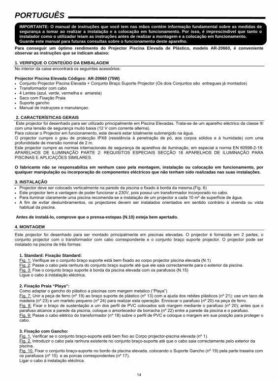
Para conseguir um óptimo rendimento do Projector Piscina Elevada de Plástico, modelo AR-20660, é conveniente observar as instruções que se indicam abaixo: 1. VERIFIQUE O CONTEÚDO DA EMBALAGEM No interior da caixa encontrará os seguintes acessórios: Projector Piscina Elevada Códigos: AR-20660 (75W) • Conjunto Projector Piscina Elevada + Conjunto Braço Suporte Projector (Os dois Conjuntos são entregues já montados) • Transformador com cabo • 4 Lentes (azul, verde, vermelha e amarela) • Saco com Fixação Praia • Suporte gancho • Manual de instruçoes e manutançao. 2. CARACTERÍSTICAS GERAIS Este projector foi desenhado para ser utilizado principalmente em Piscina Elevadas. Trata-se de um aparelho eléctrico da classe III com uma tensão de segurança muito baixa (12 V com corrente alterna). Para colocar o Projector em funcionamento, este deverá estar totalmente submergido na água. O projector cumpre o grau de protecção IPX8 (resistência à penetração de pó, aos corpos sólidos e à humidade) com uma profundidade de imersão nominal de 2 m. Este projector cumpre as normas internacionais de segurança de aparelhos de iluminação, em especial a norma EN 60598-2-18: APARELHOS DE ILUMINAÇÃO PARTE 2: REQUISITOS ESPECIAIS SECÇÃO 18 APARELHOS DE ILUMINAÇÃO PARA PISCINAS E APLICAÇÕES SIMILARES. O fabricante não se responsabiliza em nenhum caso pela montagem, instalação ou colocação em funcionamento, por qualquer manipulação ou incorporação de componentes eléctricos que não tenham sido realizadas nas suas instalações. 3. INSTALAÇÃO • Projector deve ser colocado verticalmente na parede da piscina e fixado à borda da mesma.(Fig. 6) • Este projector tem a vantagem de poder funcionar a 230V, pois possui um transformador incorporado no cabo. • Para iluminar claramente uma piscina recomenda-se a instalação de um projector a cada 10 m² de superfície de água. • A fim de evitar deslumbramentos, os projectores devem ser instalados orientados em sentido contrário à vivenda ou vista
habitual da piscina. Antes de instalá-lo, comprove que o prensa-estopas (N.10) esteja bem apertado. 4. MONTAGEM
Este projector foi desenhado para ser montado principalmente em piscinas elevadas. O projector é fornecida em 2 partes, o conjunto projector com o transformador com cabo correspondente e o conjunto braço suporte projector. O projector pode ser instalado na piscina de três formas:
1. Standard: Fixação Standard: Fig. 1: Verifique se o conjunto braço suporte está bem fixado ao corpo projector piscina elevada (N.1) Fig. 2: Passe o cabo pela ranhura do conjunto braço suporte até que ele saia correctamente para o exterior da piscina. Fig. 3: Fixe o conjunto braço suporte à borda da piscina elevada com os parafusos (N.15) Ligue o cabo à instalação eléctrica.
2. Fixação Praia “Playa”: Como adaptar o gancho do plástico a piscinas com margem metalico (“Playa”) Fig. 7: Unir a peça de ferro (nº 19) ao braço suporte de plástico (nº 13) com a ajuda dos rebites plásticos (nº 21); use um taco de madeira (nº 23) e um martelo pequeno (nº 24) para realizar esta operação. Enroscar o parafuso (nº 20) na peça de ferro. Fig. 8: Fixar o braço de sustentação a um dos perfil de PVC colocados sob margem mediante o parafuso (nº 20); antes que o parafuso alcance a parede da piscina, coloque o amortecedor de borracha (nº 22) entre a parede da piscina e o parafuso. Fig. 9: Passe o cabo elétrico do transformador (nº 18) sobre o perfil de PVC e coloque o margem em sue posição para proteger o cabo. 3. Fixação com Gancho: Fig. 1. Verificar se o conjunto braço-suporte está bem fixo ao Corpo projector-piscina elevada (nº 1). Fig. 2. Introduzir o cabo pela ranhura existente no conjunto braço-suporte até que o cabo saia correctamente pelo exterior da piscina. Fig. 10. Fixar o conjunto braço-suporte no bordo da piscina elevada, colocando o Suporte Gancho (nº 19) pela parte traseira com os parafusos (nº 15) e as porcas correspondentes (nº 17). Ligar o cabo à instalação eléctrica.
15
5. MANUTENÇÃO Para extrair o Projector da piscina, é necessário desaparafusar totalmente os dois parafusos (N.15) com uma chave de parafusos e extrair o conjunto projector e o conjunto braço suporte como se fossem uma única peça. Para substituir a lâmpada do projector, dever-se-á extrair o projector da água. Retire o friso e inverta-o de modo a que os encaixes do Friso (N.7) coincidam com os encaixes do Anel Baioneta (N.6), rode-o no sentido anti-horário. (Ver setas orientativas marcadas no friso OPEN-CLOSE) (Fig. 4). A lâmpada pode ser substituída sem necessidade de desmontar o Reflector (N.2) (Fig. 5) MUITO IMPORTANTE: Para substituir a lâmpada, utilize sempre o protector de plástico e não toque nunca a lâmpada com as mãos desprotegidas (Fig. 5). Para montar o projector , proceda do modo contrário ao descrito. Atenção: ·Antes de qualquer manipulação, assegure-se de que o projector NÃO recebe tensão. ·A lâmpada nova deve reunir as mesmas características que a fornecida com o projector, (75W) 12 V de halogéneo. ·Para assegurar uma perfeita estanqueidade, o assento da junta lente projector (N.4) deve ser limpo ou a junta substituída, se observar algum entalhe ou deformação permanente. 6. COLOCAÇÃO EM FUNCIONAMENTO Assegure-se de que a tensão que a lâmpada receba não seja em nenhuma hipótese superior a 12 V. O projector somente deve funcionar submergido e fixado às paredes verticais da piscina. Não acender nunca o projector, se ele não estiver submergido na água. 7. ADVERTÊNCIAS DE SEGURANÇA As pessoas que se encarreguem da montagem devem ter a qualificação exigida para este tipo de trabalho. • Dever-se-á evitar entrar em contacto com a tensão eléctrica. • As normas vigentes para a prevenção de acidentes devem ser respeitadas. • A esse respeito, dever-se-ão cumprir as normas IEC 364-7-702: • INSTALAÇÕES ELÉCTRICAS EM EDIFÍCIOS. INSTALAÇÕES ESPECIAIS. PISCINAS. • Qualquer operação de manutenção ou de substituição das peças deve ser realizada com o projector desligado da rede. • Não manipular o aparelho com os pés molhados.
CERTIFICADO DE GARANTIA 1. CONDIÇÕES GERAIS
1.1. De acordo com estas disposições, o vendedor garante que, no momento da entrega, o produto GRE correspondente a esta garantia (AR-20660) não apresenta nenhum tipo de falta de conformidade.
1.2. O Período de Garantia para o Produto é de dois (2) anos, contados a partir da data de entrega ao comprador. 1.3. Se, durante o período de garantia, o comprador notificar ao vendedor alguma falta de conformidade do Produto, o vendedor
deverá reparar ou substituir o Produto por sua conta no lugar onde considerar conveniente, salvo que isso seja impossível ou desmesurado.
1.4. Quando não for possível reparar ou substituir o Produto, o comprador poderá solicitar uma redução proporcional do preço ou, se a falta de conformidade for o suficientemente grave, a rescisão do contrato de venda.
1.5. As partes substituídas ou reparadas em virtude desta garantia não ampliarão o período de garantia do Produto original, mas disporão da sua própria garantia.
1.6. Para que a presente garantia tenha efeito, o comprador deverá apresentar o comprovante da data de compra e de entrega do Produto.
1.7. Se o comprador alegar uma falta de conformidade do Produto, passados mais de seis meses da data de entrega do mesmo, deverá demonstrar a origem e a existência do defeito alegado.
1.8. O presente Certificado de Garantia não limita nem afecta os direitos dos consumidores derivados das normas nacionais de carácter imperativo.
2. CONDIÇÕES PARTICULARES 2.1. A presente garantia cobre os produtos descritos neste manual. 2.2. O presente Certificado de Garantia só será válido nos países da União Europeia. 2.3. Para a eficácia desta garantia, o comprador deverá seguir rigorosamente as indicações do Fabricante contidas na
documentação fornecida com o Produto, quando a mesma for aplicável em função da gama e do modelo do Produto. 2.4. No caso de se estabelecer um calendário para a substituição, manutenção ou limpeza de determinadas peças ou
componentes do Produto, a garantia só será válida se o citado calendário tiver sido cumprido rigorosamente. 3. LIMITAÇÕES 3.1. A presente garantia só será válida para as vendas realizadas a consumidores, entendendo-se por “consumidor” a pessoa
que comprar o Produto com fins não abrangidos no âmbito da sua actividade profissional. 3.2. A garantia não cobre o desgaste normal derivado do uso do produto. Em relação às peças, componentes e/ou materiais
fungíveis ou consumíveis como pilhas, lâmpadas, etc., terá efeito o disposto na documentação fornecida com o Produto, em cada caso.
3.3. Esta garantia não abrange as seguintes situações: (I) Se o Produto tiver sido objecto de um uso incorrecto; (II) tiver sido reparado, sofrido manutenção ou manipulado por pessoas não autorizadas ou (III) tiver sido reparado ou as suas peças substituídas por peças não originais.
3.4. Quando a falta de conformidade do Produto for consequência de uma instalação ou colocação em funcionamento incorrecta, a presente garantia só será válida se a referida instalação ou colocação em funcionamento estiver incluída no contrato de compra-venda do Produto e tiver sido realizada pelo vendedor ou sob sua responsabilidade.
16
17
9
8
57 6
43
1212
11
10
13
1516
14
18
19
ENGLISH
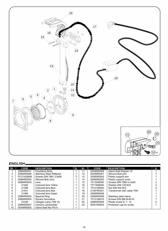
ID. CODE DESCRIPTION Q. ID. CODE DESCRIPTION Q. 1 20894R0001 Floodlamp Body 1 11 00346R0009 Gland Seal Washer 10 1 2 20894R0006 Stainless Steel Reflector 1 12 00346R0201 Silicone Butt joint 1 3 70131429095 Screws DIN 7981 2,9x95 3 13 20585R0002 Plastic support arm 1 4 20894R0005 Silicone Butt Joint 1 14 20585R0003 Plastic support cover 1 5 20894R0003 Lens 1 15 7013206050 Screws DIN 7985 m-5x50 2 5 21400 Coloured lens Yellow 1 16 7011906000 Washer DIN 125 M-6 2 5 21398 Coloured lens Blue 1 17 7012106000 Nut DIN 934 M-6 2 5 21401 Coloured lens Red 1 18 21397R0301 Transformer with cable 75W 1 5 21399 Coloured lens Green 1 19 20585R0006 1 6 20894R0002 Bayonet Ring 1 20 20894R0008 Stainless steel clamp 1 7 20894R0004 Square Decorative 1 21 7013106016 Screws DIN 966 M-6x16 1 8 23338 Halogen Lamp 75W (4) 1 22 20894R0009 Plastic screw D. 7, 13 2 9 20894R0007 Ceramic Lampholder 1 23 00251R0003 Protection cap for screw 1
10 00346R0005 Gland Seal Nut PG-9 1
17
ESPAÑOL
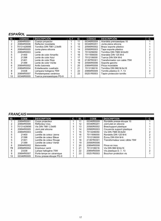
ID. CÓDIGO DESCRIPCIÓN C.T ID. CÓDIGO DESCRIPCIÓN C. 1 20894R0001 Cuerpo proyector 1 11 00346R0009 Arandela prensaestpas 10 1 2 20894R0006 Reflector inoxidable 1 12 00346R0201 Junta plana silicona 1 3 70131429095 Tornillos DIN 7981 2,9x95 3 13 20585R0002 Brazo soporte plástico 1 4 20894R0005 Junta plana silicona 1 14 20585R0003 Tapa soporte plástico 1 5 20894R0003 Lente 1 15 7013206050 Tornillos DIN 7985 M-6x50 2 5 21400 Lente de color Amarillo 1 16 7011906000 Arandela DIN 125 M-6 2 5 21398 Lente de color Azul 1 17 7012106000 Tuerca DIN 934 M-6 2 5 21401 Lente de color Rojo 1 18 21397R0301 Transformador con cable 75W 1 5 21399 Lente de color Verde 1 19 20585R0006 Soporte gancho 1 6 20894R0002 Anillo baioneta 1 20 20894R0008 Pinza inoxidable 1 7 20894R0004 Enbellecedor cuadrado 1 21 7013106016 Tornillos DIN 966 M-6x16 1 8 23338 Lámpara hológena 75W 1 22 20894R0009 Tornillo plástico D. 7, 13 2 9 20894R0007 Portalamparas cerámica 1 23 00251R0003 Tapón protección tornillo 1
10 00346R0005 Tuerca prensaestopas PG-9 1
FRANÇAIS
ID. CODE DESCRIPTION C. ID. CODE DESCRIPTION C. 1 20894R0001 Corps projecteur 1 11 00346R0009 Rondelle presse-étoupe 10 1 2 20894R0006 Réflecteur inox. 1 12 00346R0201 Joint plat en silicone 1 3 70131429095 Vis DIN 7981 2,9x95 3 13 20585R0002 Bras/support plastique 1 4 20894R0005 Joint plat silicone 1 14 20585R0003 Couvercle support plastique 1 5 20894R0003 Lentille 1 15 7013206050 Vis DIN 7985 M-6x50 2 5 21400 Lentille de coleur Janne 1 16 7011906000 Rondelle DIN 125 M-6 2 5 21398 Lentille de coleur Bleue 1 17 7012106000 Écrou DIN 934 M-6 2 5 21401 Lentille de coleur Rouge 1 18 21397R0301 Transformateur avec câble 75W 1 5 21399 Lentille de coleur Vertel 1 19 20585R0006 1 6 20894R0002 Baïonnette 1 20 20894R0008 Pince en inox. 1
7B 20894R0004 Enjoliveur carré 1 21 7013106016 Vis DIN 966 M-6x16 1 8 23338 Lampe hallogène 75W 1 22 20894R0009 Vis plastique D. 7, 13 2 9 20894R0007 Porte-lampe en céramique 1 23 00251R0003 Bouchon protéction vis 1
10 00346R0005 Écrou presse-étoupe PG-9 1
18
DEUTSCH
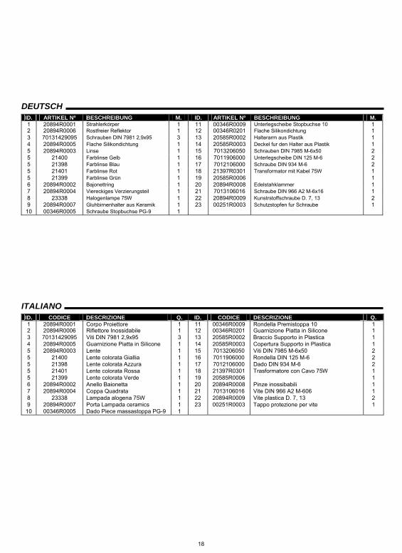
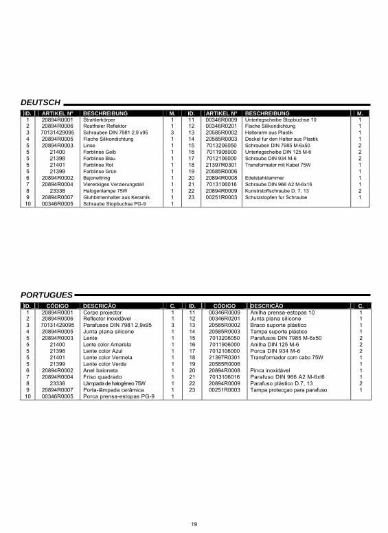
ID. ARTIKEL Nº BESCHREIBUNG M. ID. ARTIKEL Nº BESCHREIBUNG M. 1 20894R0001 Strahlerkörper 1 11 00346R0009 Unterlegscheibe Stopbuchse 10 1 2 20894R0006 Rostfreier Reflektor 1 12 00346R0201 Flache Silikondichtung 1 3 70131429095 Schrauben DIN 7981 2,9x95 3 13 20585R0002 Halterarm aus Plastik 1 4 20894R0005 Flache Silikondichtung 1 14 20585R0003 Deckel fur den Halter aus Plastik 1 5 20894R0003 Linse 1 15 7013206050 Schrauben DIN 7985 M-6x50 2 5 21400 Farblinse Gelb 1 16 7011906000 Unterlegscheibe DIN 125 M-6 2 5 21398 Farblinse Blau 1 17 7012106000 Schraube DIN 934 M-6 2 5 21401 Farblinse Rot 1 18 21397R0301 Transformator mit Kabel 75W 1 5 21399 Farblinse Grün 1 19 20585R0006 1 6 20894R0002 Bajonettring 1 20 20894R0008 Edelstahklammer 1 7 20894R0004 Viereckiges Verzierungsteil 1 21 7013106016 Schraube DIN 966 A2 M-6x16 1 8 23338 Halogenlampe 75W 1 22 20894R0009 Kunstrstoffschraube D. 7, 13 2 9 20894R0007 Gluhbirnenhalter aus Keramik 1 23 00251R0003 Schutzstopfen fur Schraube 1
10 00346R0005 Schraube Stopbuchse PG-9 1
ITALIANO
ID. CODICE DESCRIZIONE Q. ID. CODICE DESCRIZIONE Q. 1 20894R0001 Corpo Proiettore 1 11 00346R0009 Rondella Premistoppa 10 1 2 20894R0006 Riflettore Inossidabile 1 12 00346R0201 Guarnizione Piatta in Silicone 1 3 70131429095 Viti DIN 7981 2,9x95 3 13 20585R0002 Braccio Supporto in Plastica 1 4 20894R0005 Guarnizione Piatta in Silicone 1 14 20585R0003 Copertura Supporto in Plastica 1 5 20894R0003 Lente 1 15 7013206050 Viti DIN 7985 M-6x50 2 5 21400 Lente colorata Giallia 1 16 7011906000 Rondella DIN 125 M-6 2 5 21398 Lente colorata Azzura 1 17 7012106000 Dado DIN 934 M-6 2 5 21401 Lente colorata Rossa 1 18 21397R0301 Trasformatore con Cavo 75W 1 5 21399 Lente colorata Verde 1 19 20585R0006 1 6 20894R0002 Anello Baionetta 1 20 20894R0008 Pinze inossibabili 1 7 20894R0004 Coppa Quadrata 1 21 7013106016 Vite DIN 966 A2 M-606 1 8 23338 Lampada alogena 75W 1 22 20894R0009 Vite plastica D. 7, 13 2 9 20894R0007 Porta Lampada ceramics 1 23 00251R0003 Tappo protezione per vite 1
10 00346R0005 Dado Piece massastoppa PG-9 1
19
DEUTSCH
ID. ARTIKEL Nº BESCHREIBUNG M. ID. ARTIKEL Nº BESCHREIBUNG M. 1 20894R0001 Strahlerkörper 1 11 00346R0009 Unterlegscheibe Stopbuchse 10 1 2 20894R0006 Rostfreier Reflektor 1 12 00346R0201 Flache Silikondichtung 1 3 70131429095 Schrauben DIN 7981 2,9 x95 3 13 20585R0002 Halterarm aus Plastik 1 4 20894R0005 Flache Silikondichtung 1 14 20585R0003 Deckel fur den Halter aus Plastik 1 5 20894R0003 Linse 1 15 7013206050 Schrauben DIN 7985 M-6x50 2 5 21400 Farblinse Gelb 1 16 7011906000 Unterlegscheibe DIN 125 M-6 2 5 21398 Farblinse Blau 1 17 7012106000 Schraube DIN 934 M-6 2 5 21401 Farblinse Rot 1 18 21397R0301 Transformator mit Kabel 75W 1 5 21399 Farblinse Grün 1 19 20585R0006 1 6 20894R0002 Bajonettring 1 20 20894R0008 Edelstahklammer 1 7 20894R0004 Viereckiges Verzierungsteil 1 21 7013106016 Schraube DIN 966 A2 M-6x16 1 8 23338 Halogenlampe 75W 1 22 20894R0009 Kunstrstoffschraube D. 7, 13 2 9 20894R0007 Gluhbirnenhalter aus Keramik 1 23 00251R0003 Schutzstopfen fur Schraube 1
10 00346R0005 Schraube Stopbuchse PG-9 1
PORTUGUES
ID. CÓDIGO DESCRIÇÃO C. ID. CÓDIGO DESCRIÇÃO C. 1 20894R0001 Corpo projector 1 11 00346R0009 Anilha prensa-estopas 10 1 2 20894R0006 Reflector inoxidável 1 12 00346R0201 Junta plana silicone 1 3 70131429095 Parafusos DIN 7981 2,9x95 3 13 20585R0002 Braco suporte plástico 1 4 20894R0005 Junta plana silicone 1 14 20585R0003 Tampa suporte plástico 1 5 20894R0003 Lente 1 15 7013206050 Parafusos DIN 7985 M-6x50 2 5 21400 Lente color Amarela 1 16 7011906000 Anilha DIN 125 M-6 2 5 21398 Lente color Azul 1 17 7012106000 Porca DIN 934 M-6 2 5 21401 Lente color Vermela 1 18 21397R0301 Transformador com cabo 75W 1 5 21399 Lente color Verde 1 19 20585R0006 1 6 20894R0002 Anel baioneta 1 20 20894R0008 Pinca inoxidável 1 7 20894R0004 Friso quadrado 1 21 7013106016 Parafuso DIN 966 A2 M-6xl6 1 8 23338 Lãmpada de halogéneo 75W 1 22 20894R0009 Parafuso plástico D.7, 13 2 9 20894R0007 Porta-lãmpada cerãmica 1 23 00251R0003 Tampa protecçao para parafuso 1
10 00346R0005 Porca prensa-estopas PG-9 1
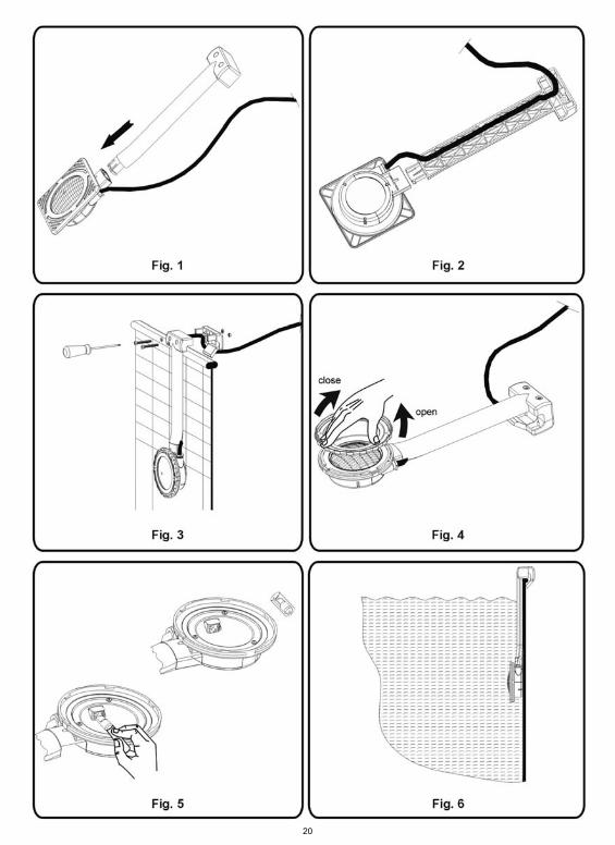
20
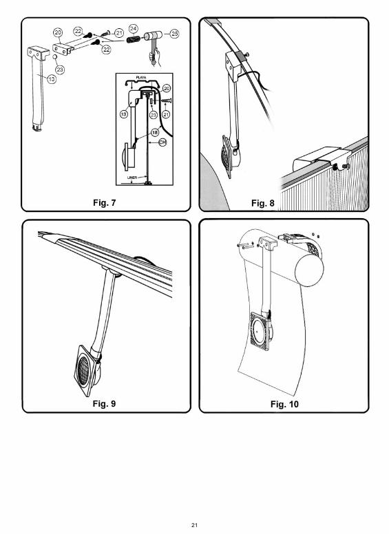
21
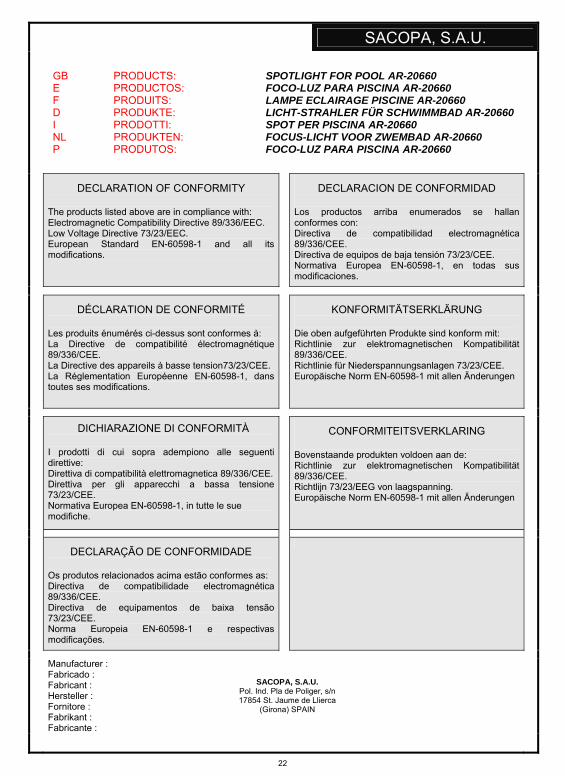
22
SACOPA, S.A.U.
GB PRODUCTS: E PRODUCTOS: F PRODUITS: D PRODUKTE: I PRODOTTI: NL PRODUKTEN: P PRODUTOS:
SPOTLIGHT FOR POOL AR-20660 FOCO-LUZ PARA PISCINA AR-20660 LAMPE ECLAIRAGE PISCINE AR-20660 LICHT-STRAHLER FÜR SCHWIMMBAD AR-20660 SPOT PER PISCINA AR-20660 FOCUS-LICHT VOOR ZWEMBAD AR-20660 FOCO-LUZ PARA PISCINA AR-20660
DECLARATION OF CONFORMITY The products listed above are in compliance with: Electromagnetic Compatibility Directive 89/336/EEC. Low Voltage Directive 73/23/EEC. European Standard EN-60598-1 and all its modifications.
DECLARACION DE CONFORMIDAD
Los productos arriba enumerados se hallan conformes con: Directiva de compatibilidad electromagnética 89/336/CEE. Directiva de equipos de baja tensión 73/23/CEE. Normativa Europea EN-60598-1, en todas sus modificaciones.
DÉCLARATION DE CONFORMITÉ Les produits énumérés ci-dessus sont conformes à: La Directive de compatibilité électromagnétique 89/336/CEE. La Directive des appareils à basse tension73/23/CEE. La Réglementation Européenne EN-60598-1, dans toutes ses modifications.
KONFORMITÄTSERKLÄRUNG
Die oben aufgeführten Produkte sind konform mit: Richtlinie zur elektromagnetischen Kompatibilität 89/336/CEE. Richtlinie für Niederspannungsanlagen 73/23/CEE. Europäische Norm EN-60598-1 mit allen Änderungen
DICHIARAZIONE DI CONFORMITÀ I prodotti di cui sopra adempiono alle seguenti direttive: Direttiva di compatibilità elettromagnetica 89/336/CEE. Direttiva per gli apparecchi a bassa tensione 73/23/CEE. Normativa Europea EN-60598-1, in tutte le sue modifiche.
CONFORMITEITSVERKLARING
Bovenstaande produkten voldoen aan de: Richtlinie zur elektromagnetischen Kompatibilität 89/336/CEE. Richtlijn 73/23/EEG von laagspanning. Europäische Norm EN-60598-1 mit allen Änderungen
DECLARAÇÃO DE CONFORMIDADE Os produtos relacionados acima estão conformes as: Directiva de compatibilidade electromagnética 89/336/CEE. Directiva de equipamentos de baixa tensão 73/23/CEE. Norma Europeia EN-60598-1 e respectivas modificações.
Manufacturer : Fabricado : Fabricant : Hersteller : Fornitore : Fabrikant : Fabricante :
SACOPA, S.A.U.
Pol. Ind. Pla de Poliger, s/n 17854 St. Jaume de Llierca
(Girona) SPAIN
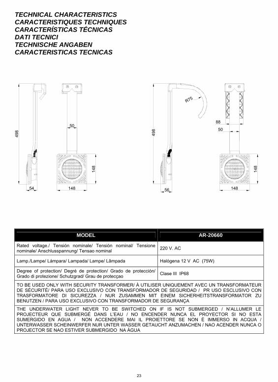
23
50
148
148
54
498
148
148
50
88
R75
498
56
TECHNICAL CHARACTERISTICS CARACTERISTIQUES TECHNIQUES CARACTERÍSTICAS TÉCNICAS DATI TECNICI TECHNISCHE ANGABEN CARACTERISTICAS TECNICAS
MODEL AR-20660
Rated voltage./ Tensión nominale/ Tensión nominal/ Tensione nominale/ Anschlusspannung/ Tensao nominal 220 V. AC
Lamp./Lampe/ Lámpara/ Lampada/ Lampe/ Lâmpada Halógena 12 V AC (75W)
Degree of protection/ Degré de protection/ Grado de protección/ Grado di protezione/ Schutzgrad/ Grau de protecçao Clase III IP68
TO BE USED ONLY WITH SECURITY TRANSFORMER/ À UTILISER UNIQUEMENT AVEC UN TRANSFORMATEUR DE SÉCURITÉ/ PARA USO EXCLUSIVO CON TRANSFORMADOR DE SEGURIDAD / PR USO ESCLUSIVO CON TRASFORMATORE DI SICUREZZA / NUR ZUSAMMEN MIT EINEM SICHERHEITSTRANSFORMATOR ZU BENUTZEN / PARA USO EXCLUSIVO CON TRANSFORMADOR DE SEGURANÇA
THE UNDERWATER LIGHT NEVER TO BE SWITCHED ON IF IS NOT SUBMERGED / N’ALLUMER LE PROJECTEUR QUE SUBMERGÉ DANS L’EAU / NO ENCENDER NUNCA EL PROYECTOR SI NO ESTA SUMERGIDO EN AGUA / NON ACCENDERE MAI IL PROIETTORE SE NON È IMMERSO IN ACQUA / UNTERWASSER SCHEINWERFER NUR UNTER WASSER GETAUCHT ANZUMACHEN / NAO ACENDER NUNCA O PROJECTOR SE NAO ESTIVER SUBMERGIDO NA ÁGUA

24
Distribuido por: MANUFACTURAS GRE, S.A.
ARITZ BIDEA Nº 57, A.C. 69 48100 MUNGUIA (VIZCAYA) SPAIN
Telf: (+34) 94 674 11 14 Fax: (+34) 94 674 17 08 Nº Reg. Ind. 48-06762
Fabricado por:
CIF: A17092610 20894E201 IP10-05 • We reserve to change all or part of the articles or contents of this document, without prior notice • Nous nous réservons le droit de modifier totalement oru en partie les carcterirstiques de nos articles ou le contenu de ce document san pré avis. • Nos reservamos el derecho de cambiar total o parcialmente las caracteristicas de nuestros articulos o contenido de este documento sin previaviso • Ci reiservamos il diritto di cambiare totalmente o parzialmente le caratteristiche tecniche dei nostri prodotti ed el contenuto di questo documento senza nessum
preavviso • Wir behalfen us das rechet vos die eigenschaften unserer produkte oder den inhalt dieses prospekter teilweiser oder wollstanding, ohne vorherige benachichtigung su
andern • Reservamos-nos no dereito de alterar, total ou parcialment as caracteristicas dos nossos artigos ou o conteúdo deste documento som aviso prévio