ENERGY RECOVERY UNITS RECUPERACIÓN DE ENERGÍA€¦ · productos relacionados con la energía en...
7
1 TECHNICAL CONCEPTS | CONCEPTOS TÉCNICOS QUÉ ES UN RECUPERADOR Un recuperador de calor es el equipo encargado de aprovechar las propiedades de tem- peratura del aire que se extrae de un edificio, sala, o local, para intercambiarlas con aire impulsado procedente del exterior. Dentro del recuperador hay una célula intercambiado- ra responsable de hacer, como su nombre indica, el intercambio de aire interior y exterior sin que se mezclen ni se pierda energía (de frío o de calor). POR QUÉ RENOVAR EL AIRE Y RECUPERAR ENERGÍA La renovación del aire en el interior de los edificios es fundamental para mantener el ambiente comfortable y saludable. Es necesario impulsar aire limpio del exterior y ex- traer o renovar el aire viciado del interior para conseguir una calidad de aire adecuada en todo espacio donde existan personas realizando alguna actividad. Cada país dispone de unas normativas concretas que regulan cómo debe hacerse esta renovación en función del volúmen del aire y de la cantidad de gente que se encuentre, así como el tipo de actividad que se desempeña en el edificio o sala. El problema de la renovación del aire en un edificio climatizado es la pérdida de energía. En invierno, con la calefacción se pierde aire caliente, y en verano con el aire acondicionado se pierde frío del interior que es expulsado directamente al exterior. En cambio, con un recupe- rador no sólo no se pierde esta energía residual sino que se aprovecha. Se hace un pretrata- miento (precalentar o preenfriar) del aire exterior, y así reducimos el consumo energético de la instalación de climatización ya que la carga térmica a combatir por aire ventilado será mucho menor gracias al pretratamiento del aire. WHAT IS A RECOVERY An energy recovery unit is the responsable of taking advantage of the properties of air temperature that is extracted from a building, room, or premises, to be exchanged with air driven from the outside. Inside the recuperator there is an exchange cell responsi- ble for making, as the name suggests, the exchange of indoor and outdoor air without mixing or losing energy (cold or heat). WHY RENEW AIR AND RECOVER ENERGY The renewal of the air inside the buildings is essential to keep the environment com- fortable and healthy. It is necessary supplying clean air from the exterior and extract or renew the stale air inside to achieve an adequate air quality in any space where there are people doing some activity. Each country has specific regulations that regulate how this renovation should be done depending on the volume of the air and the number of people who are there, as well as the type of activity performed in the building or hall. The problem of air renewal in an air-conditioned building is the loss of energy. In win- ter, hot air is lost with the heating, and in summer, with the air conditioning, the cold is lost from the interior, which is expelled directly to the outside. On the other hand, with a recuperator not only this residual energy is not lost, but it is used. A pre-treat- ment (preheat or pre-cool) of the outside air is made, and thus we reduce the energy consumption of the air conditioning system since the thermal load to be fought by ventilated air will be much lower thanks to the pre-treatment of the air. ENERGY RECOVERY UNITS RECUPERACIÓN DE ENERGÍA Clean air / aire limpio Heat/cold / calor/frío RECUPERACIÓN Y EFICIENCIA La Unión Europea establece unos requerimientos de ecodiseño (Ecodesign) para los productos relacionados con la energía en la Directiva de eficiencia energética 2012/27/ UE modificando la Directiva ErP previa. Esta directiva es parte de la meta 20-20-20, es- tablecida en el Protocolo de Kyoto, según la cual el consumo de energía debe reducirse en un 20% para el año 2020. Los recuperadores Casals que cumplen con la normativa ErP están dotados de la máxi- ma eficiencia exigida por el RITE (IDA 1, ODA 2). Esto conlleva la instalación de serie de filtros en la impulsión ePM1 70%+ePM1<80% y ePM1 70% en retorno, siendo éste el nivel más restrictivo del RITE (Reglamento de instalaciones térmicas en los edificios). ELEMENTOS DE UN RECUPERADOR DE ENERGÍA Todas las unidades de recuperación de energía se componen de 7 elementos esenciales para el cumplimiento de la normativa europea de ecodiseño ErP 2018: 1. Ventiladores para la impulsión y extracción 2. Filtros 3. Célula intercambiadora a. Contraflujo (rendimiento hasta 95%). b. Flujos cruzados (rendimiento hasta 75%). c. Rotativo (rendimiento hasta 90%, con recuperación de calor sensible y latente*). d. De celulosa (rendimiento hasta 90%) 4. Bypass parcial o total (en la aportación de aire exterior). 5. Sondas de temperatura para regular la apertura y cierre del bypass u otros elementos adicio- nales instalados en opción en el recuperador. 6. Presostatos diferenciales para la colmatación de filtros. Control (ver tabla de controles con las respectivas funciones). * Calor latente: recuperación de calor y frío con humedad. RECOVERY AND EFFICIENCY The European Union establishes ecodesign requirements (Ecodesign) for energy-rela- ted products in the Energy Efficiency Directive 2012/27 / EU by modifying the previous ErP Directive. This directive is part of the 20-20-20 target, established in the Kyoto Protocol, according to which energy consumption must be reduced by 20% by the year 2020. Casals Energy exchanger unit that comply with the ErP regulations are endowed with the maximum efficiency required by the RITE (IDA 1, ODA 2). This entails the installation of series of filters in the impulse ePM1 70%+ePM1<80% and ePM1 70% in return, this be- ing the most restrictive level of the RITE (Regulation of thermal installations in buildings). ELEMENTS OF AN ENERGY RECOVERY All the energy recovery units are composed of 7 essential elements for compliance with the European ErP 2018 eco-design regulations: 1. Fans for the drive and extraction 2. Filters 3. Exchange cell a. Backflow (yield up to 95%). b. Cross flows (yield up to 75%). c. Rotary (performance up to 90%, with sensible and latent heat recovery*). d. Cellulose (yield up to 90%). 4. Partial or total bypass (in the supply of outside air). 5. Temperature probes to regulate the opening and closing of the bypass or other additional elements installed in option in the Energy exchanger unit. 6. Differential pressure switches for filter clogging. Control (see table of controls with the respective functions). * Latent heat: recovery of heat and cold with humidity.
Transcript of ENERGY RECOVERY UNITS RECUPERACIÓN DE ENERGÍA€¦ · productos relacionados con la energía en...
1
TECHNICAL CONCEPTS | CONCEPTOS TÉCNICOS
QUÉ ES UN RECUPERADORUn recuperador de calor es el equipo encargado de aprovechar las propiedades de tem-peratura del aire que se extrae de un edificio, sala, o local, para intercambiarlas con aire impulsado procedente del exterior. Dentro del recuperador hay una célula intercambiado-ra responsable de hacer, como su nombre indica, el intercambio de aire interior y exterior sin que se mezclen ni se pierda energía (de frío o de calor).
POR QUÉ RENOVAR EL AIRE Y RECUPERAR ENERGÍALa renovación del aire en el interior de los edificios es fundamental para mantener el ambiente comfortable y saludable. Es necesario impulsar aire limpio del exterior y ex-traer o renovar el aire viciado del interior para conseguir una calidad de aire adecuada en todo espacio donde existan personas realizando alguna actividad.Cada país dispone de unas normativas concretas que regulan cómo debe hacerse esta renovación en función del volúmen del aire y de la cantidad de gente que se encuentre, así como el tipo de actividad que se desempeña en el edificio o sala.
El problema de la renovación del aire en un edificio climatizado es la pérdida de energía. En invierno, con la calefacción se pierde aire caliente, y en verano con el aire acondicionado se pierde frío del interior que es expulsado directamente al exterior. En cambio, con un recupe-rador no sólo no se pierde esta energía residual sino que se aprovecha. Se hace un pretrata-miento (precalentar o preenfriar) del aire exterior, y así reducimos el consumo energético de la instalación de climatización ya que la carga térmica a combatir por aire ventilado será mucho menor gracias al pretratamiento del aire.
WHAT IS A RECOVERYAn energy recovery unit is the responsable of taking advantage of the properties of air temperature that is extracted from a building, room, or premises, to be exchanged with air driven from the outside. Inside the recuperator there is an exchange cell responsi-ble for making, as the name suggests, the exchange of indoor and outdoor air without mixing or losing energy (cold or heat).
WHY RENEW AIR AND RECOVER ENERGYThe renewal of the air inside the buildings is essential to keep the environment com-fortable and healthy. It is necessary supplying clean air from the exterior and extract or renew the stale air inside to achieve an adequate air quality in any space where there are people doing some activity.Each country has specific regulations that regulate how this renovation should be done depending on the volume of the air and the number of people who are there, as well as the type of activity performed in the building or hall.
The problem of air renewal in an air-conditioned building is the loss of energy. In win-ter, hot air is lost with the heating, and in summer, with the air conditioning, the cold is lost from the interior, which is expelled directly to the outside. On the other hand, with a recuperator not only this residual energy is not lost, but it is used. A pre-treat-ment (preheat or pre-cool) of the outside air is made, and thus we reduce the energy consumption of the air conditioning system since the thermal load to be fought by ventilated air will be much lower thanks to the pre-treatment of the air.
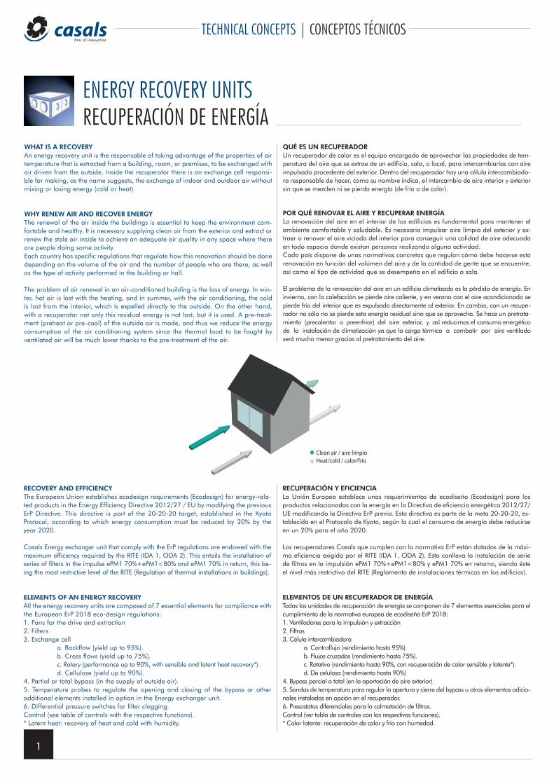
ENERGY RECOVERY UNITSRECUPERACIÓN DE ENERGÍA
Clean air / aire limpioHeat/cold / calor/frío
RECUPERACIÓN Y EFICIENCIALa Unión Europea establece unos requerimientos de ecodiseño (Ecodesign) para los productos relacionados con la energía en la Directiva de eficiencia energética 2012/27/UE modificando la Directiva ErP previa. Esta directiva es parte de la meta 20-20-20, es-tablecida en el Protocolo de Kyoto, según la cual el consumo de energía debe reducirse en un 20% para el año 2020.
Los recuperadores Casals que cumplen con la normativa ErP están dotados de la máxi-ma eficiencia exigida por el RITE (IDA 1, ODA 2). Esto conlleva la instalación de serie de filtros en la impulsión ePM1 70%+ePM1<80% y ePM1 70% en retorno, siendo éste el nivel más restrictivo del RITE (Reglamento de instalaciones térmicas en los edificios).
ELEMENTOS DE UN RECUPERADOR DE ENERGÍATodas las unidades de recuperación de energía se componen de 7 elementos esenciales para el cumplimiento de la normativa europea de ecodiseño ErP 2018:1. Ventiladores para la impulsión y extracción2. Filtros3. Célula intercambiadora
a. Contraflujo (rendimiento hasta 95%).b. Flujos cruzados (rendimiento hasta 75%).c. Rotativo (rendimiento hasta 90%, con recuperación de calor sensible y latente*).d. De celulosa (rendimiento hasta 90%)
4. Bypass parcial o total (en la aportación de aire exterior).5. Sondas de temperatura para regular la apertura y cierre del bypass u otros elementos adicio-nales instalados en opción en el recuperador.6. Presostatos diferenciales para la colmatación de filtros.Control (ver tabla de controles con las respectivas funciones).* Calor latente: recuperación de calor y frío con humedad.
RECOVERY AND EFFICIENCYThe European Union establishes ecodesign requirements (Ecodesign) for energy-rela-ted products in the Energy Efficiency Directive 2012/27 / EU by modifying the previous ErP Directive. This directive is part of the 20-20-20 target, established in the Kyoto Protocol, according to which energy consumption must be reduced by 20% by the year 2020.
Casals Energy exchanger unit that comply with the ErP regulations are endowed with the maximum efficiency required by the RITE (IDA 1, ODA 2). This entails the installation of series of filters in the impulse ePM1 70%+ePM1<80% and ePM1 70% in return, this be-ing the most restrictive level of the RITE (Regulation of thermal installations in buildings).
ELEMENTS OF AN ENERGY RECOVERYAll the energy recovery units are composed of 7 essential elements for compliance with the European ErP 2018 eco-design regulations:1. Fans for the drive and extraction2. Filters3. Exchange cell
a. Backflow (yield up to 95%).b. Cross flows (yield up to 75%).c. Rotary (performance up to 90%, with sensible and latent heat recovery*).d. Cellulose (yield up to 90%).
4. Partial or total bypass (in the supply of outside air).5. Temperature probes to regulate the opening and closing of the bypass or otheradditional elements installed in option in the Energy exchanger unit.6. Differential pressure switches for filter clogging.Control (see table of controls with the respective functions).* Latent heat: recovery of heat and cold with humidity.
2
TECHNICAL CONCEPTS | CONCEPTOS TÉCNICOS
BP
BA/BE
Filters / FiltrosFilters / Filtros
Extraction air/Extracción de aire
Supply air/Aportación de aire
OutsideExterior
InsideInterior
Extraction fan/ventilador de extración
Supply fan/Ventilador de aportación
Exchanger cell /Celula intercambiadora
Clean air inlet/Entrada de aire limpio
Stale air outlet/Salida de aire viciado
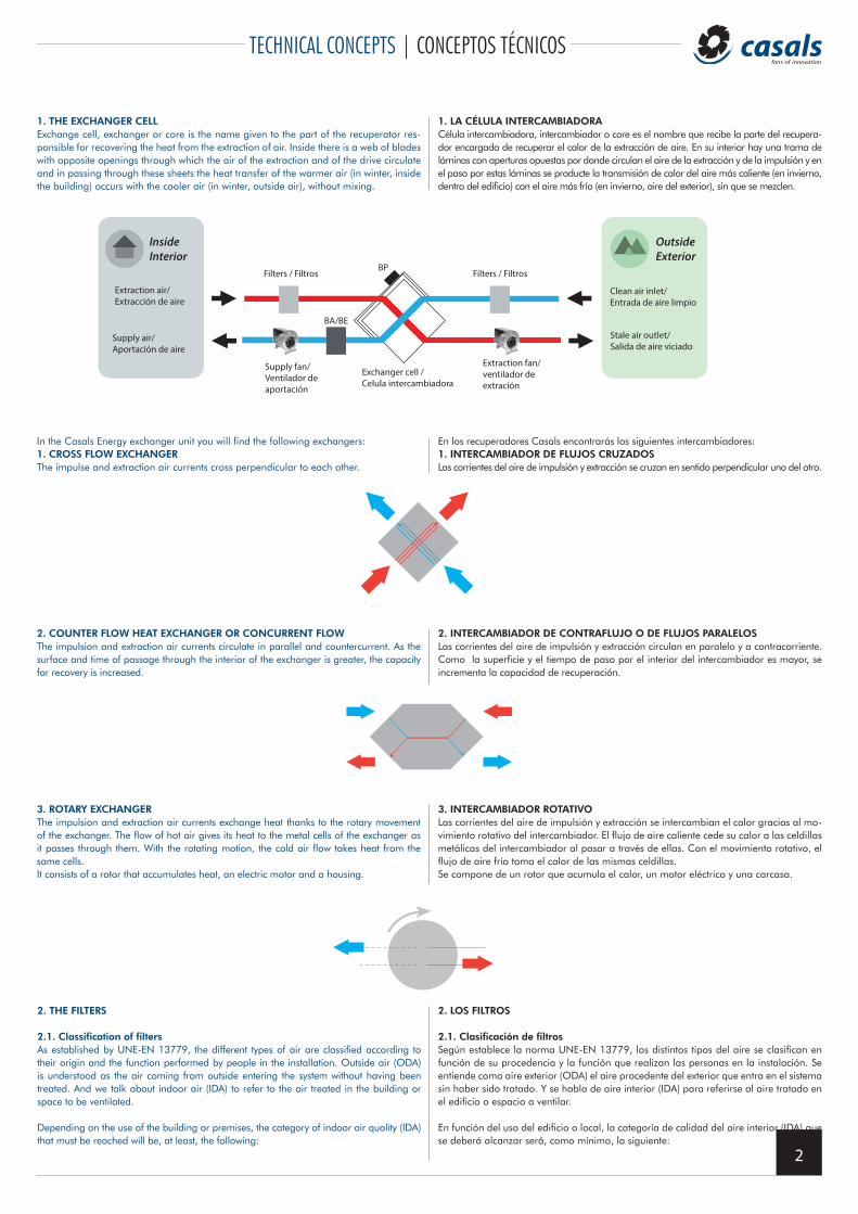
1. LA CÉLULA INTERCAMBIADORACélula intercambiadora, intercambiador o core es el nombre que recibe la parte del recupera-dor encargada de recuperar el calor de la extracción de aire. En su interior hay una trama deláminas con aperturas opuestas por donde circulan el aire de la extracción y de la impulsión y en el paso por estas láminas se producte la transmisión de calor del aire más caliente (en invierno, dentro del edificio) con el aire más frío (en invierno, aire del exterior), sin que se mezclen.
1. THE EXCHANGER CELLExchange cell, exchanger or core is the name given to the part of the recuperator res-ponsible for recovering the heat from the extraction of air. Inside there is a web of bladeswith opposite openings through which the air of the extraction and of the drive circulateand in passing through these sheets the heat transfer of the warmer air (in winter, insidethe building) occurs with the cooler air (in winter, outside air), without mixing.
In the Casals Energy exchanger unit you will find the following exchangers:1. CROSS FLOW EXCHANGERThe impulse and extraction air currents cross perpendicular to each other.
En los recuperadores Casals encontrarás los siguientes intercambiadores:1. INTERCAMBIADOR DE FLUJOS CRUZADOSLas corrientes del aire de impulsión y extracción se cruzan en sentido perpendicular uno del otro.
2. COUNTER FLOW HEAT EXCHANGER OR CONCURRENT FLOWThe impulsion and extraction air currents circulate in parallel and countercurrent. As thesurface and time of passage through the interior of the exchanger is greater, the capacityfor recovery is increased.
2. INTERCAMBIADOR DE CONTRAFLUJO O DE FLUJOS PARALELOSLas corrientes del aire de impulsión y extracción circulan en paralelo y a contracorriente.Como la superficie y el tiempo de paso por el interior del intercambiador es mayor, se incrementa la capacidad de recuperación.
3. ROTARY EXCHANGERThe impulsion and extraction air currents exchange heat thanks to the rotary movementof the exchanger. The flow of hot air gives its heat to the metal cells of the exchanger as it passes through them. With the rotating motion, the cold air flow takes heat from thesame cells.It consists of a rotor that accumulates heat, an electric motor and a housing.
3. INTERCAMBIADOR ROTATIVOLas corrientes del aire de impulsión y extracción se intercambian el calor gracias al mo-vimiento rotativo del intercambiador. El flujo de aire caliente cede su calor a las celdillasmetálicas del intercambiador al pasar a través de ellas. Con el movimiento rotativo, elflujo de aire frío toma el calor de las mismas celdillas.Se compone de un rotor que acumula el calor, un motor eléctrico y una carcasa.
2. LOS FILTROS
2.1. Clasificación de filtrosSegún establece la norma UNE-EN 13779, los distintos tipos del aire se clasifican en función de su procedencia y la función que realizan las personas en la instalación. Se entiende como aire exterior (ODA) el aire procedente del exterior que entra en el sistema sin haber sido tratado. Y se habla de aire interior (IDA) para referirse al aire tratado en el edificio o espacio a ventilar.
En función del uso del edificio o local, la categoría de calidad del aire interior (IDA) que se deberá alcanzar será, como mínimo, la siguiente:
2. THE FILTERS
2.1. Classification of filtersAs established by UNE-EN 13779, the different types of air are classified according to their origin and the function performed by people in the installation. Outside air (ODA) is understood as the air coming from outside entering the system without having been treated. And we talk about indoor air (IDA) to refer to the air treated in the building or space to be ventilated.
Depending on the use of the building or premises, the category of indoor air quality (IDA) that must be reached will be, at least, the following:
3
TECHNICAL CONCEPTS | CONCEPTOS TÉCNICOS
In the case of Casals, the Energy exchanger unit are equipped with filters to comply with the IDA 1 / ODA 2 classification:• ISO ePM1 70% (Filter F7) eff. 80-90%.• ISO ePM1 80% (Filter F9) eff. <95%.
FILTER EQUIVALENCE CHART ACCORDING TO STANDARDS
No obstante, la clasificación de los filtros se realiza en función de las ODAS (calidad de aire exterior):• ODA 1: aire puro que se ensucia sólo temporalmente (por ejemplo polen)• ODA 2: aire con concentraciones altas de partículas y/o de gases contaminantes.• ODA 3: aire con concentraciones muy altas de gases contaminantes (ODA 3G)
y/o de partículas (ODA 3P).
En el caso de Casals, los recuperadores van equipados con filtros para cumplir con laclasificación IDA 1 / ODA 2:• ISO ePM1 70% (Filter F7) eff. 80-90%.• ISO ePM1 80% (Filter F9) eff. <95%.
TABLA DE EQUIVALENCIA DE FILTROS SEGÚN NORMATIVA
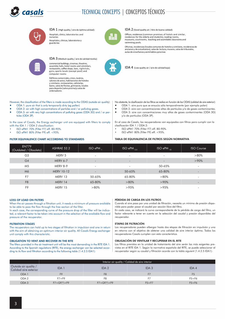
IDA 1 (High quality / aire de ópma calidad):
Hospitals, clinics, laboratories and nurseries
IDA 3 (Medium quality / aire de calidad media):
commercial buildings, cinemas, theatres, assembly halls, hotel rooms and simmilars, restaurants, coffee shops, bars, nightclubs, gyms, sports locals (except pool) and computer rooms
Hospitales, clínicas, laboratorios y guarderías
IDA 2 (Good quality air / Aire de buena calidad):
Offices, residences (common premises of hotels and similar, residences for the elderly and students), reading rooms,
teaching and assimilable classrooms andswimming pools.
IDA 4 (Low quality air / aire de calidad baja):
museums, courtrooms,
Oficinas, residencias (locales comunes de hoteles y similares, residencias de ancianos y de estudiantes), salas de lectura, museos, salas de tribunales, aulas de enseñanza y asimilables y piscinas
Edificios comerciales, cines, teatros, salones de actos, habitaciones de hoteles y similares, restaurantes, cafeterías, bares, salas de fiestas, gimnasios, locales para deporte (salvo piscina) y salas de ordenadores
However, the classification of the filters is made according to the ODAS (outside air quality):• ODA 1: pure air that is only temporarily dirty (eg pollen)• ODA 2: air with high concentrations of particles and / or polluting gases.• ODA 3: air with very high concentrations of polluting gases (ODA 3G) and / or par-
ticles (ODA 3P).
Interior air quality / Calidad de aire interior
Outside air quality /Calidad aire exterior IDA 1 IDA 2 IDA 3 IDA 4
ODA 1 F9 F8 F7 F5
ODA 2 F7+F9 F8 F7 F5+F6
ODA 3 F7+GF(*)+F9 F7+GF(*)+F9 F5+F7 F5+F6
LOSS OF LOAD ON FILTERSWhen the air passes through a filtration unit, it needs a minimum of pressure available to be able to pass the flow through the free section of the filter.In each case, the corresponding curve of the pressure drop of the filter will be indica-ted, a relevant factor to be taken into account in the selection of the available flow and pressure of the recuperator.
FILTRATION STAGESThe recuperators can hold up to two stages of filtration in impulsion and one in return with the aim of obtaining an optimum interior air quality. All Casals Energy exchanger unit comply with this characteristic.
OBLIGATION TO VENT AND RECOVER IN THE RITEThe filters provided in the air treatment unit will be the most demanding in the RITE IDA 1.According to the Spanish regulations (RITE), the energy exchanger can be selected accor-ding to its flow and filtration according to the following table (1.4.2.5 IDA1):
PÉRDIDA DE CARGA EN LOS FILTROSCuando el aire pasa por una unidad de filtración, necesita un mínimo de presión dispo-nible para poder pasar el caudal por sección libre del filtro. En cada caso, se indicará la curva correspondiente de la pérdida de carga del filtro, un factor relevante a tener en cuenta en la selección del caudal y presión disponibles del recuperador.
ETAPAS DE FILTRACIÓNLos recuperadores pueden albergar hasta dos etapas de filtración en impulsión y una en retorno con el objetivo de obtener una calidad de aire interior óptima. Todos los recuperadores Casals cumplen con esta característica.
OBLIGACIÓN DE VENTILAR Y RECUPERAR EN EL RITELos filtros previstos en la unidad de tratamiento del aire serán las más exigentes pre-vistas en el RITE IDA 1. Según la normativa española del RITE, se puede seleccionar el recuperador según su caudal y filtración acorde con la tabla siguient (1.4.2.5 IDA1):
EN779 (Outdated / Obsoleto)
ASHRAE 52.2 ISO ePM 1 ISO ePM 2.5 ISO ePM 10 ISO Course
G3 MERV 5 - - - >80%
G4 MERV 6-7 - - - >90%
M5 MERV 8-9 - - 50-65% -
M6 MERV 10-12 - 50-65% 65-80% -
F7 MERV 13 50-65% 65-80% >80% -
F8 MERV 14 65-80% >80% >90% -
F9 MERV 15 >80% >95% >95% -
4
TECHNICAL CONCEPTS | CONCEPTOS TÉCNICOS
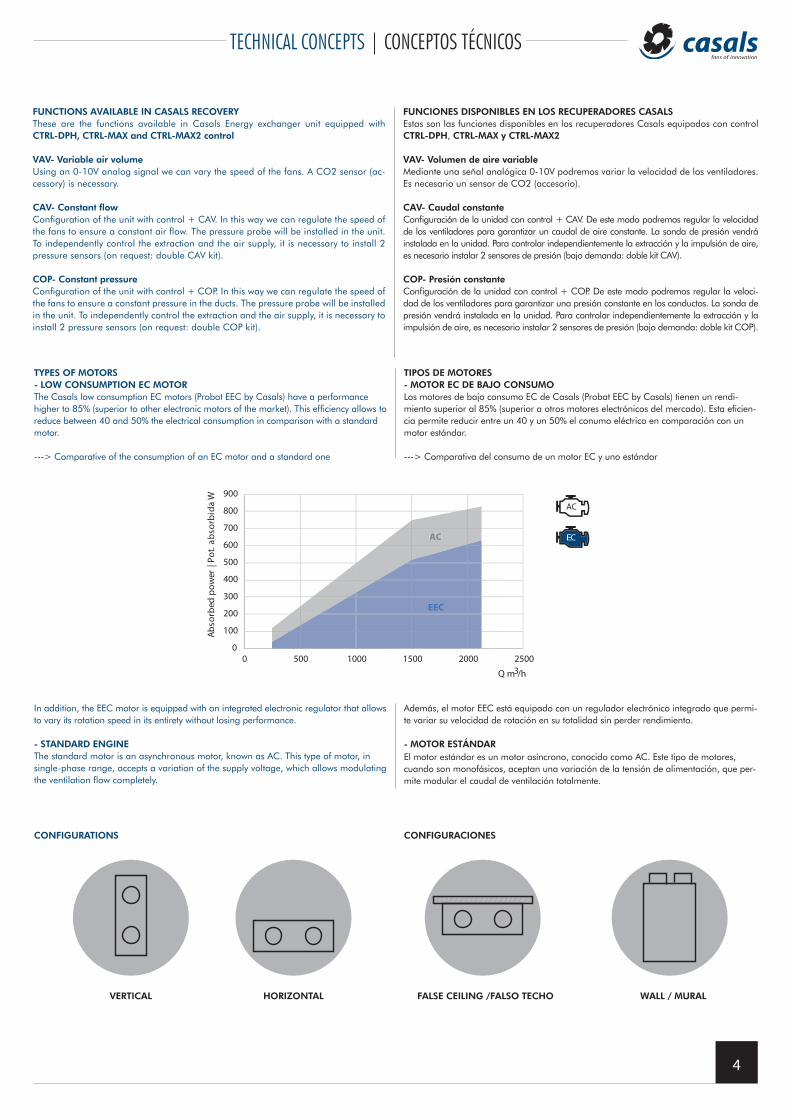
TIPOS DE MOTORES - MOTOR EC DE BAJO CONSUMOLos motores de bajo consumo EC de Casals (Probat EEC by Casals) tienen un rendi-miento superior al 85% (superior a otros motores electrónicos del mercado). Esta eficien-cia permite reducir entre un 40 y un 50% el conumo eléctrico en comparación con un motor estándar.
---> Comparativa del consumo de un motor EC y uno estándar
TYPES OF MOTORS - LOW CONSUMPTION EC MOTORThe Casals low consumption EC motors (Probat EEC by Casals) have a performance higher to 85% (superior to other electronic motors of the market). This efficiency allows to reduce between 40 and 50% the electrical consumption in comparison with a standard motor.
---> Comparative of the consumption of an EC motor and a standard one
CONFIGURATIONS CONFIGURACIONES
In addition, the EEC motor is equipped with an integrated electronic regulator that allows to vary its rotation speed in its entirety without losing performance.
- STANDARD ENGINEThe standard motor is an asynchronous motor, known as AC. This type of motor, insingle-phase range, accepts a variation of the supply voltage, which allows modulatingthe ventilation flow completely.
Además, el motor EEC está equipado con un regulador electrónico integrado que permi-te variar su velocidad de rotación en su totalidad sin perder rendimiento.
- MOTOR ESTÁNDAREl motor estándar es un motor asíncrono, conocido como AC. Este tipo de motores,cuando son monofásicos, aceptan una variación de la tensión de alimentación, que per-mite modular el caudal de ventilación totalmente.
0
100
200
300
400
500
600
700
800
900
0 500 1000 1500
EEC
AC
2000 2500
Abso
rbed
pow
er |
Pot.
abso
rbid
a W
Q m3/h
VERTICAL HORIZONTAL FALSE CEILING /FALSO TECHO WALL / MURAL
FUNCTIONS AVAILABLE IN CASALS RECOVERYThese are the functions available in Casals Energy exchanger unit equipped with CTRL-DPH, CTRL-MAX and CTRL-MAX2 control
VAV- Variable air volumeUsing an 0-10V analog signal we can vary the speed of the fans. A CO2 sensor (ac-cessory) is necessary.
CAV- Constant flowConfiguration of the unit with control + CAV. In this way we can regulate the speed of the fans to ensure a constant air flow. The pressure probe will be installed in the unit. To independently control the extraction and the air supply, it is necessary to install 2 pressure sensors (on request: double CAV kit).
COP- Constant pressureConfiguration of the unit with control + COP. In this way we can regulate the speed of the fans to ensure a constant pressure in the ducts. The pressure probe will be installed in the unit. To independently control the extraction and the air supply, it is necessary to install 2 pressure sensors (on request: double COP kit).
FUNCIONES DISPONIBLES EN LOS RECUPERADORES CASALSEstas son las funciones disponibles en los recuperadores Casals equipados con control CTRL-DPH, CTRL-MAX y CTRL-MAX2
VAV- Volumen de aire variableMediante una señal analógica 0-10V podremos variar la velocidad de los ventiladores. Es necesario un sensor de CO2 (accesorio).
CAV- Caudal constanteConfiguración de la unidad con control + CAV. De este modo podremos regular la velocidad de los ventiladores para garantizar un caudal de aire constante. La sonda de presión vendrá instalada en la unidad. Para controlar independientemente la extracción y la impulsión de aire, es necesario instalar 2 sensores de presión (bajo demanda: doble kit CAV).
COP- Presión constanteConfiguración de la unidad con control + COP. De este modo podremos regular la veloci-dad de los ventiladores para garantizar una presión constante en los conductos. La sonda de presión vendrá instalada en la unidad. Para controlar independientemente la extracción y la impulsión de aire, es necesario instalar 2 sensores de presión (bajo demanda: doble kit COP).
5
CONTROL FUNCTIONS | FUNCIONES DE CONTROLES
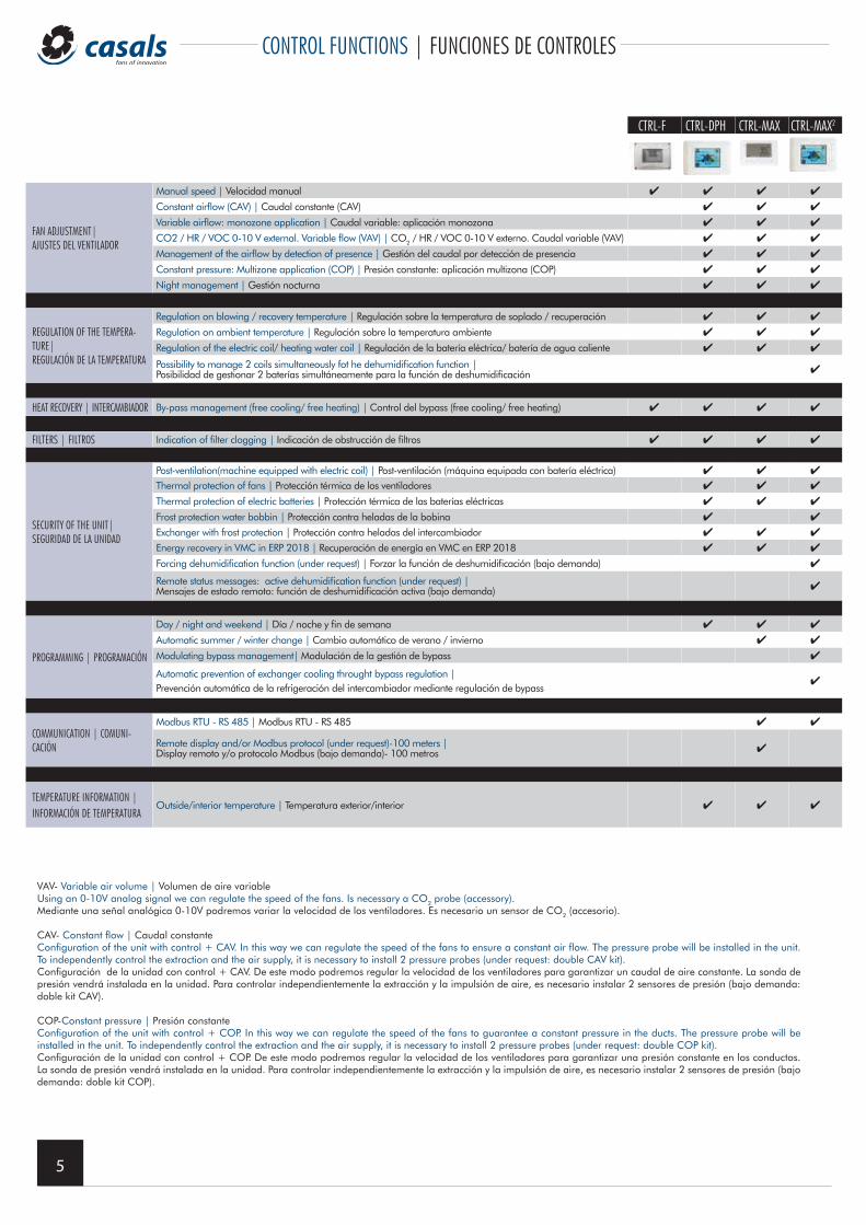
VAV- Variable air volume | Volumen de aire variableUsing an 0-10V analog signal we can regulate the speed of the fans. Is necessary a CO2 probe (accessory).Mediante una señal analógica 0-10V podremos variar la velocidad de los ventiladores. Es necesario un sensor de CO2 (accesorio).
CAV- Constant flow | Caudal constanteConfiguration of the unit with control + CAV. In this way we can regulate the speed of the fans to ensure a constant air flow. The pressure probe will be installed in the unit. To independently control the extraction and the air supply, it is necessary to install 2 pressure probes (under request: double CAV kit).Configuración de la unidad con control + CAV. De este modo podremos regular la velocidad de los ventiladores para garantizar un caudal de aire constante. La sonda de presión vendrá instalada en la unidad. Para controlar independientemente la extracción y la impulsión de aire, es necesario instalar 2 sensores de presión (bajo demanda: doble kit CAV).
COP-Constant pressure | Presión constanteConfiguration of the unit with control + COP. In this way we can regulate the speed of the fans to guarantee a constant pressure in the ducts. The pressure probe will be installed in the unit. To independently control the extraction and the air supply, it is necessary to install 2 pressure probes (under request: double COP kit).Configuración de la unidad con control + COP. De este modo podremos regular la velocidad de los ventiladores para garantizar una presión constante en los conductos. La sonda de presión vendrá instalada en la unidad. Para controlar independientemente la extracción y la impulsión de aire, es necesario instalar 2 sensores de presión (bajo demanda: doble kit COP).
CTRL-F CTRL-DPH CTRL-MAX CTRL-MAX2
FAN ADJUSTMENT| AJUSTES DEL VENTILADOR
Manual speed | Velocidad manual 4 4 4 4
Constant airflow (CAV) | Caudal constante (CAV) 4 4 4
Variable airflow: monozone application | Caudal variable: aplicación monozona 4 4 4
CO2 / HR / VOC 0-10 V external. Variable flow (VAV) | CO2 / HR / VOC 0-10 V externo. Caudal variable (VAV) 4 4 4
Management of the airflow by detection of presence | Gestión del caudal por detección de presencia 4 4 4
Constant pressure: Multizone application (COP) | Presión constante: aplicación multizona (COP) 4 4 4
Night management | Gestión nocturna 4 4 4
REGULATION OF THE TEMPERA-TURE|REGULACIÓN DE LA TEMPERATURA
Regulation on blowing / recovery temperature | Regulación sobre la temperatura de soplado / recuperación 4 4 4
Regulation on ambient temperature | Regulación sobre la temperatura ambiente 4 4 4
Regulation of the electric coil/ heating water coil | Regulación de la batería eléctrica/ batería de agua caliente 4 4 4
Possibility to manage 2 coils simultaneously fot he dehumidification function |Posibilidad de gestionar 2 baterías simultáneamente para la función de deshumidificación 4
HEAT RECOVERY | INTERCAMBIADOR By-pass management (free cooling/ free heating) | Control del bypass (free cooling/ free heating) 4 4 4 4
FILTERS | FILTROS Indication of filter clogging | Indicación de obstrucción de filtros 4 4 4 4
SECURITY OF THE UNIT| SEGURIDAD DE LA UNIDAD
Post-ventilation(machine equipped with electric coil) | Post-ventilación (máquina equipada con batería eléctrica) 4 4 4
Thermal protection of fans | Protección térmica de los ventiladores 4 4 4
Thermal protection of electric batteries | Protección térmica de las baterías eléctricas 4 4 4
Frost protection water bobbin | Protección contra heladas de la bobina 4 4
Exchanger with frost protection | Protección contra heladas del intercambiador 4 4 4
Energy recovery in VMC in ERP 2018 | Recuperación de energía en VMC en ERP 2018 4 4 4
Forcing dehumidification function (under request) | Forzar la función de deshumidificación (bajo demanda) 4
Remote status messages: active dehumidification function (under request) |Mensajes de estado remoto: función de deshumidificación activa (bajo demanda) 4
PROGRAMMING | PROGRAMACIÓN
Day / night and weekend | Día / noche y fin de semana 4 4 4
Automatic summer / winter change | Cambio automático de verano / invierno 4 4
Modulating bypass management| Modulación de la gestión de bypass 4
Automatic prevention of exchanger cooling throught bypass regulation | Prevención automática de la refrigeración del intercambiador mediante regulación de bypass
4
COMMUNICATION | COMUNI-CACIÓN
Modbus RTU - RS 485 | Modbus RTU - RS 485 4 4
Remote display and/or Modbus protocol (under request)-100 meters | Display remoto y/o protocolo Modbus (bajo demanda)- 100 metros 4
TEMPERATURE INFORMATION |INFORMACIÓN DE TEMPERATURA
Outside/interior temperature | Temperatura exterior/interior 4 4 4
6
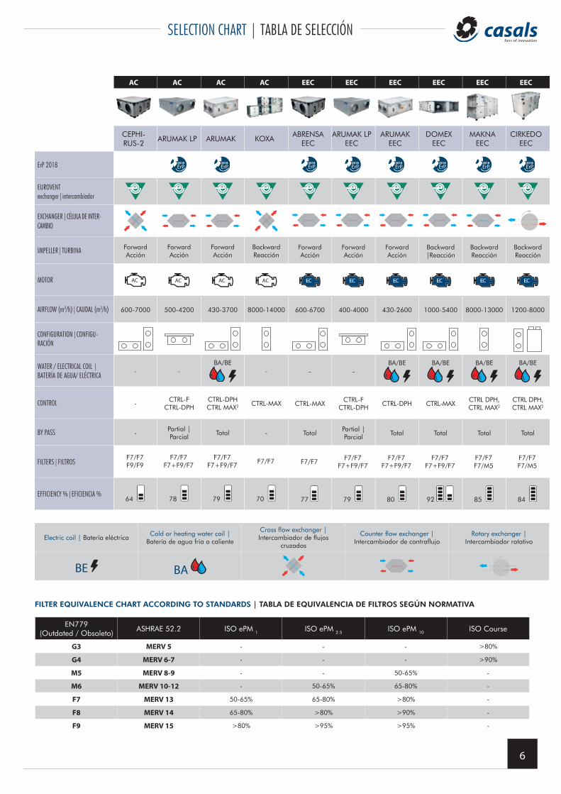
SELECTION CHART | TABLA DE SELECCIÓN
AC AC AC AC EEC EEC EEC EEC EEC EEC
CEPHI-RUS-2
ARUMAK LP ARUMAK KOXAABRENSA
EECARUMAK LP
EECARUMAK
EECDOMEX
EECMAKNA
EECCIRKEDO
EEC
ErP 2018 2018 2018 2018 2018 2018 2018 2018 2018
EUROVENTexchanger|intercambiador
EXCHANGER|CÉLULA DE INTER-CAMBIO
IMPELLER|TURBINA Forward Acción
Forward Acción
Forward Acción
BackwardReacción
Forward Acción
Forward Acción
Forward Acción
Backward |Reacción
BackwardReacción
BackwardReacción
MOTOR
AIRFLOW (m3/h)|CAUDAL (m3/h) 600-7000 500-4200 430-3700 8000-14000 600-6700 400-4000 430-2600 1000-5400 8000-13000 1200-8000
CONFIGURATION|CONFIGU-RACIÓN
WATER / ELECTRICAL COIL |BATERÍA DE AGUA/ ELÉCTRICA
- -
BA/BE- - -
BA/BE BA/BE BA/BE BA/BE
CONTROL -CTRL-F
CTRL-DPHCTRL-DPHCTRL MAX2 CTRL-MAX CTRL-MAX
CTRL-FCTRL-DPH
CTRL-DPH CTRL-MAXCTRL DPH, CTRL MAX2
CTRL DPH, CTRL MAX2
BY PASS -Partial | Parcial
Total - TotalPartial | Parcial
Total Total Total Total
FILTERS|FILTROSF7/F7F9/F9
F7/F7F7+F9/F7
F7/F7F7+F9/F7
F7/F7 F7/F7F7/F7
F7+F9/F7F7/F7
F7+F9/F7F7/F7
F7+F9/F7F7/F7F7/M5
F7/F7F7/M5
EFFICIENCY %|EFICIENCIA %64 78 79 70 77 79 80 92 85 84
Electric coil | Batería eléctricaCold or heating water coil |
Batería de agua fría o caliente
Cross flow exchanger |Intercambiador de flujos
cruzados
Counter flow exchanger |Intercambiador de contraflujo
Rotary exchanger |Intercambiador rotativo
BE BA
EN779 (Outdated / Obsoleto)
ASHRAE 52.2 ISO ePM 1 ISO ePM 2.5 ISO ePM 10 ISO Course
G3 MERV 5 - - - >80%
G4 MERV 6-7 - - - >90%
M5 MERV 8-9 - - 50-65% -
M6 MERV 10-12 - 50-65% 65-80% -
F7 MERV 13 50-65% 65-80% >80% -
F8 MERV 14 65-80% >80% >90% -
F9 MERV 15 >80% >95% >95% -
FILTER EQUIVALENCE CHART ACCORDING TO STANDARDS | TABLA DE EQUIVALENCIA DE FILTROS SEGÚN NORMATIVA
7
ERP DIRECTIVE | DIRECTIVA ERP
ERP ECODESIGN DIRECTIVE 2009/125/CE -LOT 6- HEAT EXCHANGER UNITS
1. All ventilation units, except fans with more than one application range (for example, fans used for both ventilation and flue gas extraction) mustbe equipped with a variable speed controller or stepper.
2. All bidirectional ventilation units must have a heat recovery and thermal bypass system.3. The heat recovery system will have a thermal bypass. This means regulation of heat recovery between 1-100%.4. In double-flow air ventilation units, the minimum thermal efficiency of all heat recovery systems with balanced air flow (except for circulating fluid
systems) will be effective as of January 1, 2018: Minimum 73 %.5. In double-flow air ventilation units, the minimum thermal efficiency of the heat recovery systems with water coils in the balanced air flow will be
as of January 1, 2018: Minimum 68%.6. The relation between the specific fan power fan (SFP) and the efficiency of the heat recovery system is specified in a formula. If the efficiency in
heat recovering, for example, is greater than 67%, a higher specific fan power (SFP) is allowed. This requirement will be implemented in twosteps. The first step was implemented on January 1, 2016; and the second, with stricter demands, on January 1, 2018. First, a new value of SFPcalled SFPint is created. The SFPint is a theoretical value to allow an efficiency limit for different configurations of the recovery unit. The SFPint iscalculated with clean ISO ePM10 50% (M5) filters in return, with clean filters ISO ePM 70% (F7) in air supply, the exchanger itself and the air flowin the recovery unit. In Spain, the R.I.T.E. (Regulation of Thermal Installations in Buildings) that establishes criteria linked to the ERP EcodesignDirective 2009/125/CE.
DIRECTIVA ERP ECODESIGN 2009/125/CE -LOTE 6- RECUPERADORES DE CALOR
1. Todas las unidades de ventilación, excepto los ventiladores con más de un rango de aplicación (por ejemplo, ventiladores utilizados tanto parala ventilación como para la extracción de gases de combustión) deben estar equipados con un controlador de velocidad variable o paso a paso.
2. Todas las unidades de ventilación bidireccionales deberán disponer de un sistema de recuperación de calor y bypass térmico.3. El sistema de recuperación de calor tendrá una derivación térmica. Esto significa regulación de recuperación de calor entre 1-100%.4. En las unidades de ventilación de doble flujo de aire, la eficiencia térmica mínima de todos los sistemas de recuperación de calor con flujo de
aire equilibrado (excepto los sistemas de líquidos circulantes) será a partir del 1 de enero de 2018: Mínimo 73%.5. En las unidades de ventilación de doble flujo de aire, la eficiencia térmica mínima de los sistemas de recuperación de calor con baterías de agua
en el flujo de aire balanceado será a partir del 1 de enero de 2018: Mínimo 68%.6. La relación entre la potencia específica del ventilador (SFP) y la eficiencia del sistema de recuperación de calor se especifica en una fórmula. Si
la eficiencia en la recuperación de calor, por ejemplo, es superior al 67%, se permite una mayor potencia específica del ventilador (SFP). Esterequisito se implementará en dos pasos. El primer paso se implementó el 1 de enero de 2016, y el segundo, con demandas más estrictas, el 1de enero de 2018. Primero se crea un nuevo valor de SFP llamado SFPint. El SFPint es un valor teórico para permitir un límite de eficiencia paradiferentes configuraciones del recuperador. El SFPint se calcula con los filtros ISO ePM10 50% (M5) en retorno limpios, con los filtros ISO ePM 70%(F7) limpios en impulsión, el propio recuperador y el flujo de aire en la unidad de recuperación. En España, hay que tener en cuenta la R.I.T.E.(Reglamento de Instalaciones Térmicas en Edificios) que establece unos criterios ligados a la Directiva ERP Ecodesign 2009/125/CE.