Diseño de Sistemas Eléctricos I: Residencial y Comercial
35
Diseño de Sistemas Eléctricos I: Residencial y Comercial Dr. Lionel R. Orama Exclusa, PE enero de 2006
Transcript of Diseño de Sistemas Eléctricos I: Residencial y Comercial

Diseño de Sistemas Eléctricos I: Residencial y Comercial
Dr. Lionel R. Orama Exclusa, PEenero de 2006

18-Jan-2006 INEL 4407 © L.R.Orama/ A. Irizarry 2006
2
Introducción al DiseñoI. ¿Qué es diseño?
A. Trabajo en equipo (arq., inci, inme, inel)B. Interesante, pero con complicaciones
1. el papel aguanta todo2. el campo no3. la sociedad tampoco
C. Limitaciones (“constraints”) que cumplirD. Certificado por Ingeniero LicenciadoE. Existen Códigos y ReglamentosF. Ética

INEL 4407 © L.R.Orama/ A. Irizarry 2006
3
Puerto Rico’s Laws• Electrical Design must be certified by a
licensed engineer
• Graduate from a Credited University
• Board Exams (“reválida”) must be approved
•Fundamental, Professional
• Active Member of CIAPR
•Two years of supervised engineering
experience
• The design must comply with:• National Electrical Code (NEC)
• “Reglamento Complementario al Código
Eléctrico Nacional (AEE)”

INEL 4407 © L.R.Orama/ A. Irizarry 2006
4
Proceso de DiseñoII. Proceso
A. Propuestas de diseño, arq. Solicita costos de electricidad para el proyecto
B. En general, INEL último en comenzar y terminar una vez se aprueba la propuesta
C. La AEE tiene que Endosar el proyecto1. Si la carga computada >50kVA (200A)2. Pasos para solicitar endoso
a. Estudio de campo; líneas y voltaje disponiblesb. Proyectos grandes, estudio de corto circuito
c. Punto de conexión, donde se conectaran las líneas del edificio con las de la AEE

INEL 4407 © L.R.Orama/ A. Irizarry 2006
5
Electrical Design for Buildings• Electrical systems do not exist on a vacuum
– They are part of a product, a sub-system of an equipment or an structure
• In this course we will confine ourselves to design of electrical systems for buildings– Residential - small and large dwellings units, multiple
dwellings (apartments)– Commercial – general purpose units, offices, dining– Industrial – basic, light industrial facilities

INEL 4407 © L.R.Orama/ A. Irizarry 2006
6
El diseño en sí
A. Computo de cargas1. Tablas para estimados (RS Means-Electrical Cost Data,
otros), para propuesta2. Por diseño, utilizando como guía el NEC
B. Circuitos ramales de iluminaciónC. Circuitos ramales de receptáculos D. Circuitos ramales para cargas de potencia
1. Acondicionadores de aire2. Elevadores y escaleras automáticas3. Otros, equipos de cocina, etc.
E. Alimentadores y paneles de distribuciónF. Subestación y bases de contadores

20-Jan-2006 INEL 4407 © L.R.Orama/ A. Irizarry 2006
7
National Electrical Code (NEC)• National Fire Protection Association (NFPA) &
the American National Standards Institute
(ANSI) regards the Code as purely advisory
• States make it mandatory i.e. it becomes Law
with the exceptions, provisions, clarifications
that the State decides to adopt, hence the
“Reglamento Complementario al Código
Eléctrico Nacional” in Puerto Rico
• Can be difficult to read and understand– Reading the NEC from beginning to end is worst
than reading a dictionary from beginning to end

INEL 4407 © L.R.Orama/ A. Irizarry 2006
8
NEC Article 90 - Introduction
90-1 Purpose
a) Practical Safeguarding. The purpose of the
code is the practical safeguarding of persons
and property from hazards arising from the
use of electricity
b) Adequacy – compliance (with the Code) and
proper maintenance will result in an
installation free from hazard but not
necessarily efficient, convenient or adequate
for good service or future expansion of
electrical use.

INEL 4407 © L.R.Orama/ A. Irizarry 2006
9
National Electrical CodeArticle 90 - Introduction
90-1 Purpose
c) Intention. This Code is not intended as a
design specification nor an instruction
manual for untrained persons.
90-2 Scope
a) Covered1. Installation of electric conductors and equipment
within or on public and private buildings or other
structures (mobile homes, recreational vehicles,
floating bldg, yards, carnivals, parking, other lots,
and industrial substations.

INEL 4407 © L.R.Orama/ A. Irizarry 2006
10
National Electrical CodeArticle 90 - Introduction
90-2 Scope
b) Not Covered1. Installations in ships, watercrafts other than
floating bldg, railway rolling stock, aircraft, or
automobile vehicles other than mobile homes and
recreational vehicles.
2. Installations underground in mines
3. Installations of railways for generation,
transformation, transmission, or distribution to
operate rolling stock, signaling and
communications

INEL 4407 © L.R.Orama/ A. Irizarry 2006
11
National Electrical CodeArticle 90 - Introduction
90-2 Scope
b) Not Covered
4. Installations of communication equipment under
the exclusive control of communication utilities
located outdoors or in building spaces
exclusively for such installations.
5. Installations under the exclusive control of
electric utilities for the purpose of
communications, metering, generation, control,
transformation, transmission or distribution of
electric energy.

INEL 4407 © L.R.Orama/ A. Irizarry 2006
12
National Electrical CodeArticle 90 - Introduction
90-3 Code ArrangementIntroduction and nine chapters
Ch. 1-4 apply generally
Ch. 5-7 special occupancies, special equipment or
other special conditions. Ch. 1-4 apply except as
amended by Ch. 5-7 for the particular conditions.
Ch. 8 covers communications systems and it is
independent of the other chapters except where
they are specifically referenced therein.
Ch. 9 are Tables

INEL 4407 © L.R.Orama/ A. Irizarry 2006
13
National Electrical CodeArticle 90 - Introduction
90-8 Wiring Planninga) Future Expansion and Convenience.
• Future expansion via ample space in raceways
• Convenience via readily accessible distribution
centers
b) Number of Circuits in Enclosures.
• The number of wires and circuits confined in a
single enclosure will be varyingly restricted.
• Limiting the number of circuits in a single
enclosure will minimize the effects from a short
circuit or ground fault in one circuit.

23-Jan-2006 INEL 4407 © L.R.Orama/ A. Irizarry 2006
14
Reglamento Complementario al Código Eléctrico Nacional (AEE)
• Published by the Puerto Rico Electric Power Authority (PREPA) – the authority having jurisdiction
• Defines electrical constructions in three types
1. Tipo 1 – instalaciones eléctricas interiores y exteriores2. Tipo 2 – distribución eléctrica – urbanizaciones o lotes3. Tipo 3 – extensiones de líneas eléctricas – instalaciones
de líneas para llevar facilidades eléctricas desde líneasde la AEE hasta urbanizaciones, lotes y edificios
*For every installation over 50kVA it includes substations

INEL 4407 © L.R.Orama/ A. Irizarry 2006
15
Reglamento Complementario al Código Eléctrico Nacional
Seccion II Disposiciones GeneralesArtículo A. PropósitoEstablece, junto al NEC, las normas y requisitos mínimos
necesarios para garantizar la seguridad de personas y estructuras en la instalación de conductores y equipoeléctrico en Puerto Rico.
INEL 4407 © L.R.Orama/ A. Irizarry 2006
16
ANSI Std Y32.9 – 1972 (1989)The standard provides a basis for1) Showing the general physical location and
arrangement of the sections of the required wiring system
2) Identifying the physical requirements for various types of materials needed to provide the electrical installation in buildings
INEL 4407 © L.R.Orama/ A. Irizarry 2006
17
Drafting Graphic Symbols• Electrical layouts shall be drawn:
– to an appropriate scale or figure dimensions noted– on drawing sheets separate from the architectural
or structural drawings or the drawing sheets for mechanical or other facilities.
– Clearly. DO NOT lay out on the same drawing sheet all different electrical systems to be installed in the same building area. Use separate drawing sheets for different systems such as signal system outlets and circuits vs. lighting and power branch circuit wiring.
INEL 4407 © L.R.Orama/ A. Irizarry 2006
18
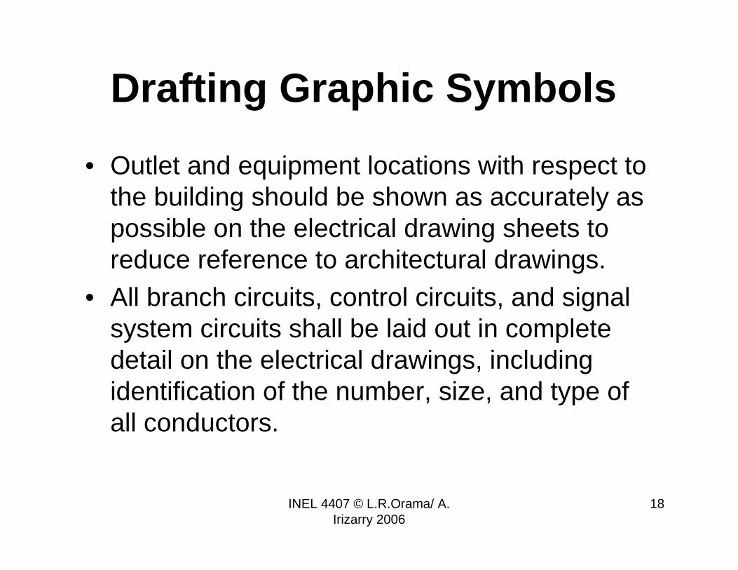
Drafting Graphic Symbols
• Outlet and equipment locations with respect to the building should be shown as accurately as possible on the electrical drawing sheets to reduce reference to architectural drawings.
• All branch circuits, control circuits, and signal system circuits shall be laid out in complete detail on the electrical drawings, including identification of the number, size, and type of all conductors.

INEL 4407 © L.R.Orama/ A. Irizarry 2006
19
Drafting Graphic Symbols
Complete drawings of the design shall have:• Floor plan layout, to scale, of all outlet and
equipment locations and wiring runs• A complete schedule of all of the symbols used with
appropriate description of the requirements• Riser diagram showing the physical relationship of
the service, feeder and major power runs, unit substations, isolated power transformers, switchboards, panel boards, pull boxes, terminal cabinets, and other systems and equipment.

INEL 4407 © L.R.Orama/ A. Irizarry 2006
20
Drafting Graphic Symbols
4) Where necessary for clearness. a single line diagram showing the electrical relationship of the component items and sections of the wiring system.
5) Where necessary to provide adequate information, elevations, sections and details of equipment and special installations, anddetails of special lighting fixtures and devices
6) Sections of the building or elevation of the structure showing floor-to-floor, outlet, and equipment heights, relation to the established grade, general type of building construction, etc. Where practicable, suspended ceiling heights indicated by figure dimensions on either the electrical floor plan layout drawings or on the electrical building section or elevation drawings

INEL 4407 © L.R.Orama/ A. Irizarry 2006
21
Drafting Graphic Symbols
7) Where necessary to provide adequate information, plot plan to scale, showing the relation of the building or structure to other buildings or structures, service poles, service manholes, exterior area lighting, exterior wiring runs, etc
8) In the case of exterior wiring systems for street and highway lighting, area drawings showing the complete system
9) Any changes to the electrical layout should be clearly indicated on the drawings, when such changes are made after the original drawings have been completed, and should be identified on the drawing by a revision symbol

INEL 4407 © L.R.Orama/ A. Irizarry 2006
22
Examples of Electrical Symbols on an Architectural Plan
Outlet (“salida”)– a point on a
wiring system where current
is taken to supply utilization
equipment
• receptacle outlet – an
outlet where one or more
receptacles are installed
single
duplex
Insulated GroundIG
receptacle outlets symbols
WPWater Proof
GFCIGround Fault Circuit
Interrupter
triplex
RRange
DClothes Dryer
F
C
Fan
Clock
Floor Outlet
Floor Single
Floor Duplex
Single
Floor Special
Purpose

INEL 4407 © L.R.Orama/ A. Irizarry 2006
23
Examples of Electrical Symbols on an Architectural Plan
lighting outlet – an outlet
intended for the direct
connection of a lampholder,
lightning fixture, or a
pendant cord terminating in
a lampholder.
incandescent
incandescent
wall
lighting outlets symbols
X
RX
surface or
pendant exit
recessed exit
surface fluorescent surface fluorescent
wall
J junction box
X
RX
surface or
pendant exit (wall)
recessed exit (wall)
J junction box wall
INEL 4407 © L.R.Orama/ A. Irizarry 2006
24
Examples of Electrical Symbols on an Architectural Plan
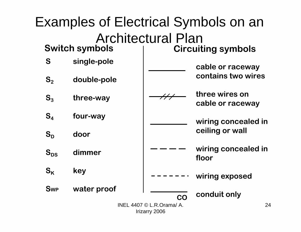
Switch symbols
cable or raceway
contains two wires
three wires on
cable or raceway
wiring concealed in
ceiling or wall
wiring concealed in
floor
wiring exposed
conduit only
Circuiting symbols
S single-pole
S2 double-pole
S3 three-way
S4 four-way
SD door
SDS dimmer
SK key
SWP water proofCO

INEL 4407 © L.R.Orama/ A. Irizarry 2006
25
Examples of Electrical Symbols on an Architectural Plan
push button
buzzer
bell
telephone
(private system)
telephone
(outside line)
thermostat
motor
T
M
lighting panel
power panel
heating panel
transformer
television outlet
circuit breaker
overcurrent protection
device
T
TV

INEL 4407 © L.R.Orama/ A. Irizarry 2006
26
System voltages
There may be several system voltages available to supply a given load but not all service voltages are available for any load.
• 3Ø service may not be available for residential loads• For 3Ø service a minimum load may be required• Minimum service voltage may be specified for large loads
INEL 4407 © L.R.Orama/ A. Irizarry 2006
27
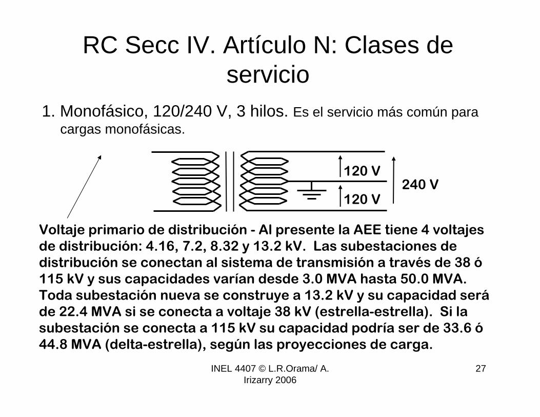
RC Secc IV. Artículo N: Clases de servicio
1. Monofásico, 120/240 V, 3 hilos. Es el servicio más común paracargas monofásicas.
120 V
120 V240 V
Voltaje primario de distribución - Al presente la AEE tiene 4 voltajes
de distribución: 4.16, 7.2, 8.32 y 13.2 kV. Las subestaciones de
distribución se conectan al sistema de transmisión a través de 38 ó
115 kV y sus capacidades varían desde 3.0 MVA hasta 50.0 MVA.
Toda subestación nueva se construye a 13.2 kV y su capacidad será
de 22.4 MVA si se conecta a voltaje 38 kV (estrella-estrella). Si la
subestación se conecta a 115 kV su capacidad podría ser de 33.6 ó
44.8 MVA (delta-estrella), según las proyecciones de carga.

INEL 4407 © L.R.Orama/ A. Irizarry 2006
28
120 V
120 V240 V

INEL 4407 © L.R.Orama/ A. Irizarry 2006
29
1Ø transf. connections
(a) and (b) show two
secondary coils
rated at 120 V
connected in
parallel to supply a
two-wire 120 V
circuit. No longer
used.
(c) and (d) show two
secondary coils
rated at 120 V
connected in series
to supply a three-
wire 120/240 V
circuit.
a b
c d

INEL 4407 © L.R.Orama/ A. Irizarry 2006
30
RC Secc IV. Artículo N: Clases de servicio2. Trifásico, 208Y/120 V, 4 hilos. Común para cargas trifásicas
pequeñas.
120 V
208 V
primario en ∆
208 V
208 V
120 V
120 V
Sirve cargas trifásicas a 208 y cargas monofásicas a 208 y 120 V

INEL 4407 © L.R.Orama/ A. Irizarry 2006
31
3Ø transformer connections – ∆Y four wire grounded secondary

INEL 4407 © L.R.Orama/ A. Irizarry 2006
32
RC Secc IV. Artículo N: Clases de servicio3. Trifásico, 480Y/277 V, 4 hilos. Común para cargas trifásicas
mayores.
277 V
480 V
primario en ∆
480 V
480 V
277 V
277 V
Sirve cargas trifásicas a 480 y cargas monofásicas a 277 y 480 V

INEL 4407 © L.R.Orama/ A. Irizarry 2006
33
Otros (NO en RC)Trifásico, 240 V (ó 480) V, 3 hilos.
240 V (ó 480 V)
primario en ∆
Sirve cargas trifásicas a 240 V (ó 480 V) entre las fases A, B y C
Sirve cargas monofásicas a 240 V (ó 480 V) entre dos fases
B
A
C
240 V (ó 480 V)

INEL 4407 © L.R.Orama/ A. Irizarry 2006
34
RC Secc IV. Artículo B: Asuntos Generales
• Se requiere subestación (1Ø ó 3Ø) para cualquier tipo de edificio con carga calculada mayor de 50 kVA.
• Cualquier edificion con carga estimada que no exceda 75 kVA 1Ø ó 150 kVA 3Ø puede servirse de un transformadoro banco de transformadores instalado en poste de hormigón de 40 pies mínimo (o entre dos postes de hormigón de 40 pies mínimo o estructura de metal certificada para servir graveros, hormigoneras y edificios en construcción).
• En areas con problemas de espacio se permitirá, con permiso de la AEE, subestaciones 1Ø de 75 kVA en postesde la AEE si la subestación sirve más de un cliente.

INEL 4407 © L.R.Orama/ A. Irizarry 2006
35
References1. NFPA 70, National Electrical Code, NFPA, 2005.2. Reglamento Complementario al Código Eléctrico Nacional,
AEE, 2000.3. ANSI Std Y32.9 – 1972 (1989) American National Standard
Graphic Symbols for Electrical Wiring and Layout Diagrams Used in Architecture and Building Construction. American National Standard Institute.