Brochure Gasificacion
2
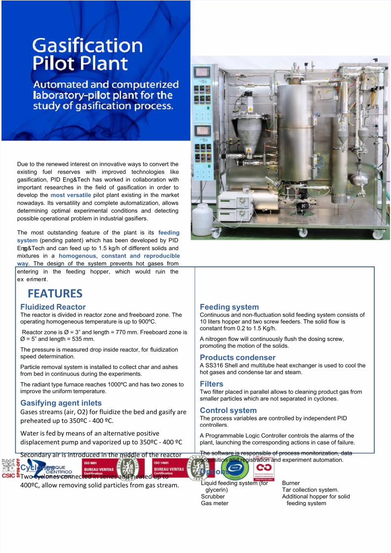
Due to the renewed interest on innovative ways to convert the existing fuel reserves with improved technologies like gasification, PID Eng&Tech has worked in collaboration with important researches in the field of gasification in order to develop the most versatile pilot plant existing in the market nowadays. Its versatility and complete automatization, allows determining optimal experimental conditions and detecting possible operational problem in industrial gasifiers. The most outstanding feature of the plant is its feeding system (pending patent) which has been developed by PID Eng&Tech and can feed up to 1.5 kg/h of different solids and mixtures in a homogenous, constant and reproducible way. The design of the system prevents hot gases from entering in the feeding hopper, which would ruin the ex er iment. FEATURES Fluidized Reactor The reactor is divided in reactor zone and freeboard zone. The operating homogeneous temperature is up to 900ºC. Reactor zone is Ø = 3” and length = 770 mm. Freeboard zone is Ø = 5” and length = 535 mm. The pressure is measured drop inside reactor, for fluidization speed determination. Particle removal system is installed to c ollect char and ashes from bed in continuous during the experiments. The radiant type furnace reaches 1000ºC and has two zones to improve the uniform temperature. Gasifying agent inlets Gases streams (air, O2) for fluidize the bed and gasify are preheated up to 350ºC - 400 ºC. Water is fed by means of an alternative positive displacement pump and vaporized up to 350ºC - 400 ºC Secondary air is introduced in the middle of the reactor Cyclones Two cyclones connected in series and heated up to 400ºC, allow removing solid particles from gas stream. Feeding system Continuous and non-fluctuation solid feeding system consists of 10 liters hopper and two screw feeders. The solid flow is constant from 0.2 to 1.5 Kg/h. A nitrogen flow will continuously flush the dosing screw, promoting the motion of the solids. Products condenser A SS316 Shell and multitube heat exchanger is used to cool the hot gases and condense tar and steam. Filters Two filter placed in parallel allows to cleaning product gas from smaller particles which are not separated in cyclones. Control system The process variables are controlled by independent PID controllers. A Programmable Logic Controller controls the alarms of the plant, launching the corresponding actions in case of failure. The software is responsible of process monitorization, data acquisition and registration and experiment automation. Options Burner Tar collection system. Additional hopper for solid feeding system Liquid feeding system (for glycerin) Scrubber Gas meter
-
Upload
lew-chee-cheong -
Category
Documents
-
view
231 -
download
0
Transcript of Brochure Gasificacion
7/30/2019 Brochure Gasificacion
http://slidepdf.com/reader/full/brochure-gasificacion 1/2
Due to the renewed interest on innovative ways to convert the
existing fuel reserves with improved technologies like
gasification, PID Eng&Tech has worked in collaboration with
important researches in the field of gasification in order to
develop the most versatile pilot plant existing in the marketnowadays. Its versatility and complete automatization, allows
determining optimal experimental conditions and detecting
possible operational problem in industrial gasifiers.
The most outstanding feature of the plant is its feeding
system (pending patent) which has been developed by PID
Eng&Tech and can feed up to 1.5 kg/h of different solids and
mixtures in a homogenous, constant and reproducible
way. The design of the system prevents hot gases from
entering in the feeding hopper, which would ruin the
ex eriment.
FEATURESFluidized Reactor The reactor is divided in reactor zone and freeboard zone. Theoperating homogeneous temperature is up to 900ºC.
Reactor zone is Ø = 3” and length = 770 mm. Freeboard zone isØ = 5” and length = 535 mm.
The pressure is measured drop inside reactor, for fluidizationspeed determination.
Particle removal system is installed to collect char and ashesfrom bed in continuous during the experiments.
The radiant type furnace reaches 1000ºC and has two zones toimprove the uniform temperature.
Gasifying agent inletsGases streams (air, O2) for fluidize the bed and gasify are
preheated up to 350ºC - 400 ºC.
Water is fed by means of an alternative positive
displacement pump and vaporized up to 350ºC - 400 ºC
Secondary air is introduced in the middle of the reactor
CyclonesTwo cyclones connected in series and heated up to
400ºC, allow removing solid particles from gas stream.
Feeding systemContinuous and non-fluctuation solid feeding system consists of 10 liters hopper and two screw feeders. The solid flow isconstant from 0.2 to 1.5 Kg/h.
A nitrogen flow will continuously flush the dosing screw,promoting the motion of the solids.
Products condenser A SS316 Shell and multitube heat exchanger is used to cool thehot gases and condense tar and steam.
FiltersTwo filter placed in parallel allows to cleaning product gas fromsmaller particles which are not separated in cyclones.
Control systemThe process variables are controlled by independent PIDcontrollers.
A Programmable Logic Controller controls the alarms of theplant, launching the corresponding actions in case of failure.
The software is responsible of process monitorization, dataacquisition and registration and experiment automation.
Options
Burner Tar collection system. Additional hopper for solid
feeding system
Liquid feeding system (for glycerin)Scrubber Gas meter
7/30/2019 Brochure Gasificacion
http://slidepdf.com/reader/full/brochure-gasificacion 2/2
PROCESS@ SOFTWARE
The pilot plant includes process system
and electronic control system. All these
systems are consisting on a distributed
control based on PC that has the
Process@ software, based on digital RS-
485 communications between controllers
and management control system for
supervisory control and data acquisition.
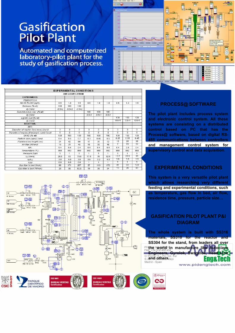
EXPERIMENTAL CONDITIONS
This system is a very versatile pilot plant
which allows researching very different
feeding and experimental conditions, such
as temperature, gas flow in bed, air flow,
residence time, pressure, particle size…
GASIFICATION PILOT PLANT P&I
DIAGRAM
The whole system is built with SS316materials, SS310 for the reactor and
SS304 for the stand, from leaders all over
the world in manufacture like Autoclave
Engineers, Gyrolok, Swagelok, Head Line
and others.